1
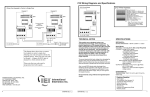
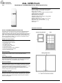
834L VIPER PLUS
FRAME MOUNT GLASSBREAK/SELECTIVE VIBRATION DETECTOR
Specifications
Operating Voltage: 10-15VDC (filtered and regulated)
Power Consumption: 6mA (normal); 13mA (alarm)
Range: Up to 10 ft. radius
Voltage Monitor: Low or No Voltage cause alarm activation
Voltage Supervision: Alarm Relay
Relay Activation Time: 8 seconds
Alarm LED: Latch or auto-reset
Alarm Relay: SPST (form A) contacts, 0.5A @ 30VDC
Installation: Hardwire 4 wires
Operating Temperature: 0 ° to 120 ° F (-20° to 50°C)
Mounting: Surface – screws included
Sensor Size: 3.35” long x 0.90” wide x 1.00” high
Weight: 2.1 ounces
Color: White
Installation Instructions
IEI 834L GLASSBREAK/VIBRATION DETECTOR
The IEI 834L Viper Plus with Contact is a frame mount glassbreak/selective
vibration detector. The Viper Plus contains a custom integrated circuit
designed specifically to detect vibration signals associated with forced entry in
a wide variety of surfaces including: windows, doors, walls and glass of all
types. You can adjust the Viper Plus for sensitivity over a wide range, but it’s
immune to low frequency vibration. The Viper Plus is a standalone sensor
with no additional processor required.
IEI 834L Viper Plus Features
•
•
•
•
•
•
•
•
•
•
Patented Integrated Circuit Design
Solid-State Piezoelectric Device
No Separate Processor Required
Latching Alarm LED
Auto Reset Alarm Relay
Simplified Calibration Test Mode
Cover Tamper Contact
Double Knock Feature For Alarm Verification
Immune to Low Frequency Vibration
High-Low Sensitivity Jumper
Auto-Reset Relay
When the Viper Plus goes into alarm, the relay contact remains open for 8
seconds before re-closing to detect a second independent attack, if
necessary.
Cover Tamper Contact
The cover is monitored against unwanted sensitivity changes or tampering
with a switch mounted on the circuit board. This switch is internally wired in
series with the alarm relay. No additional wiring is necessary.
Double Knock Mode
Most unwanted signals fade within 200 milliseconds. Prolonged attack or
breaking glass exceeds this time. When Double Knock Mode is enabled and
the Viper Plus detects a signal above set sensitivity level it enters the active
mode but ignores all levels of signal for approximately 200 milliseconds. If the
vibration remains above the set sensitivity level for more than 200
milliseconds, or a second attack exceeds the set sensitivity level within 8
seconds, the Viper Plus goes into alarm.
Calibration Test Mode
The first time you trip your Viper Plus there is an 8 second delay before the
LED turns on (the relay opens for 8 seconds as it normally does). After this
first trip the LED remains on and shows each subsequent trip by turning off for
8 seconds. When you are finished testing, interrupt the power to reset the
LED for normal operation.
Document # 6153400, Rev. 3.1
Mounting the Viper Plus
Calibrating the Viper Plus
Mount the Viper Plus on the door or window frame, as shown in the illustrated
examples. Do not install across structural members or at joints in construction
in frames or bridge any other two components in a structure. Make sure you
mount the Viper Plus on a flat surface, clear of bumps or grit. Also verify the
mounting surface is in good physical condition with no loose or rattling parts.
You must take additional care when installing in areas accessible to the
public. In areas where protection is required for larger areas and low
sensitivity desired for better false alarm rejection (such as windows adjacent
to a public sidewalk) use two Vipers.
The Viper Plus has a test feature that eliminates the need to manually reset
power during testing. The first time you trip the Viper Plus there is an 8
second delay before the LED turns on (the relay opens for 8 seconds as it
normally does). After the first trip the LED remains on and shows each
subsequent trip by turning off for 8 seconds. When finished with testing,
interrupt power to reset the LED for normal operation. To disable the LED
turn dipswitch 2 off.
To remove the cover, unscrew the retaining screw on the front. The unit
consists of two pieces, the cover and the base plate with the circuit board.
Position the base plate on the surface and mark the mounting holes. The selftapping screws are suitable for most materials. For metal frames, drill a 3/32”
pilot hole. Be careful not to damage the circuit board in the base plate when
driving screws.
You should set the sensitivity as low as possible to reduce the change of false
alarms. The Viper Plus has a High-Low jumper setting to increase or
decrease its sensitivity. With the jumper in place, the Viper is set for Low
sensitivity mode. By removing the jumper, the Viper becomes more sensitive.
To set the sensitivity, use the IEI-815 calibration tool. This device puts a
predetermined amount of shock into the window or doorframe. If you don’t
have the IEI-815 tool, simply protect the surface and impact it with a hard
object like a small hamper or the back of a screwdriver, taking care not to
damage the surface.
Note: When mounted, the cover must not make contact with another surface.
Wiring the Viper Plus
You can run the wires either through the back of the base plate using the wire
slot (for concealed wiring - see diagram), or through the bottom of the cover
using the rubber grommet. To use the grommet you must cut out the area on
the bottom of the cover indicated by the indentations on the inside.
When mounting vertically install the Viper Plus so the wires enters from the
bottom of the unit, to prevent water entry. When mounting horizontally,
remember to add a drip to loop to prevent water from running along the wires
and entering the case.
The diagram below shows the four terminal strip connections. Attach power
leads to +12VDC and GND terminals. When connecting the power, you must
observer polarity. Also, use a filtered and regulated power supply, with at
least four hours of standby time. You should also provide a switch or other
circuit to interrupt power to reset a latched alarm LED (if selected).
Attach a normally closed loop from your control panel to the remaining tamper
loop terminals. These are “open” until the Viper Plus is powered up. The
cover tamper switch and magnetic reed switch are in series with the alarm
relay circuit. These must be in place for the circuit to close.
When finished wiring, secure the cover onto the base plate and turn on the
power.
Trip the Viper Plus at the limit of protection desired. Remember that the Viper
Plus will respond to one large blow or several small ones. Where it’s likely
that more than one blow is required to breach a window or door, apply several
“hits” of the IEI 815 within an 8 second period to simulate the shock to set the
sensitivity. Calibrate around the extremities of the area and progressively
decrease sensitivity by rotating the sensitivity adjustment potentiometer
counter clockwise. When you reach a point where the Viper Plus no longer
trips, slightly increase the sensitivity until the LED response is obtained.
DO NOT USE THE CALIBRATION TOOL DIRECTLY ON GLASS!
Double Knock Setting
For increased resistance to false alarms use the “double knock” feature.
After the initial shock, the Viper Plus continues to analyze the signal for
another 8 seconds. If another large shock or several smaller ones occur
within the next 8 seconds the Viper Plus goes into alarm. To enable this
feature set dipswitch 1 to off. This feature is ideal for laminated and
bulletproof glass.
IEI Limited Warranty
Because the manufacturer does not install or connect this security device the
manufacturer cannot guarantee its performance. Therefore, there are not
warranties, expressed or implied (except as stated below), attached to the
sale of this product.
The manufacturer warrants against defects in material an workmanship in this
device for 3 years from the date of manufacture. During the warranty period
the manufacturer, at its sole option, will repair or replace free of charge any
defective unit returned freight prepaid. This warranty shall remain in force and
effect for 3 years provided the unit was properly installed and operated, has
not been subject to misuse and has not been repaired or altered other than by
the original manufacturer.
The forgoing states the buyer’s sole and exclusive remedy for any breach of
warranty or for any claim, whether sounding in contract, tort, strict liability, or
negligence, based upon any defect in this security device.
The manufacturer shall in no event be responsible for any incidental or
consequential damages incurred by the buyer.
This warranty supersedes all previous warranties.
International Electronics, Inc.
427 Turnpike St.
Canton, MA 02021
1-800-343-9502 (outside MA)
www.ieib.com
Document # 6153400, Rev. 3.1