1
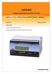
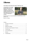
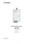
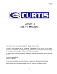
1
Device for transmitting messages over cellular channel
Programming and connection manual
1. Device assignment and principle of operation
Module is designed for connection to cellular phones and transmission of alarm
messages to ordinary telephones (speech transactions only) or cellular phones. It can be
used together with Nokia 6110, 6130, 5110, 5130, and Siemens C35 phones.
The module can operate in one mode or in two modes simultaneously.
1. When one of three zones is actuated, the device dials on specified phone numbers
and transmits textual (SMS), speech transaction or Email (if it is supported by used
GSM network). The device supports operation with all types of sensors having
output of “dry contact” type. User can set normally closed or normally open alarm
output during device programming.
2. When the module is connected to digital communicator terminals of control panel, it
can convert signals of Contact ID format into SMS messages and transmit them
over cellular communication channel.
To program the module in the first operational mode use one of two methods: complete
programming from computer (using cidconf.exe program) or partial programming from
connected cellular device. Software functions on IBM PC/AT computers operated by
Windows 95/98, NT, Win 2000, or WinXP. СОМ port of computer is used for
programming.
Texts of short messages, speech phrases (in the form of wav file), and adjustment of
Contact ID convector messages (second operational mode of the module) are programmed
only by means of personal computer.
2. Technical specifications
2.1
2.2
2.3
2.4
Supply voltage - 12 V
Consumption current - 30мА, at 300мА battery charging
Three zones without current supervision
One transistor output 300мА
1.
2.
3.
4.
5.
6.
7.
8.
9.
Supply voltage +12 Volt
Ground (GND)
Transistor output (PGM)
Zone 1 (Z1)
Zone 2 (Z2)
Zone 3 (Z3)
Microphone input (MIC)
Ground (GND)
Split for telephone
Communicator input
connection
Split for programming
PRG
1 2 3 4 5 6 7 8 9
123456789
2
2. Connection
Connect/disconnect telephone to module only at power OFF.
Mount the module in dry place, close to battery backup. Place GSM terminal so that
antenna was located at the farthest distance from wire communication devices.
Module supply +12V, GND terminals
Relay contacts (GND zone terminal) or transistor open collector may be connected to
zones (Z1, Z2, Z3 terminals).
PIN-code of SIM-card must be switched OFF! Phone switches off at prolonged power
absence. The device activates phone automatically at energizing.
PGM is a normally open transistor output changing to minus at activation. PGM stands up
to 300mA current. The output is preserved with recover safety device.
Connect “Plus” of LED or buzzer to +12V connection terminal, and “Minus” - to PGM
programmable output.
Communicator of control panel is connected to LINE and GND terminals. Polarity is of
NO importance.
MIC terminal is for future use.
3. Module operation without control panel protocol converter.
Module stores 8 phone numbers, 6 short messages, 3 voice messages, total sound time is
12 seconds. It is possible to transmit textual SMS in specified period or once per day.
PGM output is activated at receipt of SMS with digital password.
Each zone has 1..4 phone numbers assigned, where voice message or SMS will be
transmitted. Type of zone is break or shortage.
Phone numbers, zone function, number of short messages centre, password for PGM
activation and textual SMS transaction time is entered in phone SIM-card. Information of
notebook is transferred to nonvolatile memory of cellular dialer at power ON.
Texts of short messages and voice messages are programmed using personal computer;
moreover, it is possible to transmit SMS characters using Cyrillic alphabet as well as Roman
alphabet.
The module permanently supervises state of GSM terminal battery. When battery is
discharged for ¾ the device automatically switches ON battery charging unit. At battery’ total
charge the module automatically disconnects charging unit from telephone, thus observing
operational environment of the battery.
5. Module operation in mode of protocol converter of control panel
When the module is connected to digital communicator of control panel it can convert
signals of Ademco contact ID format into SMS messages and transmit them over cellular
communication channel. The message is displayed in the following way:
AAAA P CCC XX ZZZ
where AAAA is panel code, P - status (new event/restored), CCC- event ID, XXnumber of guard or group subsystem, ZZZ – number of zone or user. Moreover, system user
can adjust AAAA, XX and ZZ independently. For example, message in ID format - 1111 1
402 01 040 may be received by abonent as Cottage 1 System disarmed 1st floor Brown, which
means: receipt of new event from cottage - user Brown disarmed first floor.
3
6. Brief description of program configuration
Configuration of cidconf.exe program is intended for preparation of “Cellular dialer” to
operation by means of programming of necessary options, namely user messages, phone
numbers, sound message and so on. Program operates on IBM PC/AT computers with
Windows 95/98, NT, Win2000, WinXP operational systems. Computer serial port is used for
programming.
Program capability:
• Reading of current configuration from device
• Visual image of current configuration
• Adjusting configuration according to module outputs
• Adjusting module operation as Contact ID protocol converter
• Downloading user configuration to device
• Recording voice messages
• Listening to recorded voice messages
• Saving configuration into file
7. Description of cidconf.exe program
«About program» menu displays version of program.
In «File» menu set number of serial port, where the module is connected. Connect cable
for programming to COM-port of computer or to the module.
Press "Open port" button to start working with serial port. After successful port opening,
the rest of operational buttons become deblocked.
When settings are entered into programming sheets, they can be loaded into the module
and saved into file in “Project” section. Data of settings and voice messages can be saved into
file with *.rom extension.
*.wav files of 8000Hz, 11025Hz, 22050Hz, 8bit and mono formats can be loaded into
module. Six voice messages can be recorded in the module.
Total duration of messages is determined by sampling frequency of source sound file
and corresponds to the table below:
Sampling frequency, Hz
Duration, seconds
22050
12
11025
24
8000
32
When sampling frequency is decreased, sound quality is deteriorated. Indicator of voice
messages memory overload indicates presence of free memory space.
In «Telephones» menu, enter numbers of phones for transmission of voice messages
(dialer) and transmission of short messages. “+” preceding phone number switches
international format. Some cellular operators use only international format for transmission of
short messages.
In «Messages» menu, enter text of short messages. It is possible to transmit data in
Cyrillic letters.
«Zones» section relates only to three physical zones of the module. Select for each
“Action” (in case of zone break) a number of phone and SMS message variant, as well as
phone number and voice message variant. Remember to specify type of zone – break or
shortage. At zone break up to 4 “Actions” may be executed. For each action, first, short SMS
messages are transmitted and then dialer activates. Number of dialer complete cycles, that is
from 3 up to 9, is programmed in “Properties” section.
In «Properties» menu, necessarily enter number of short messages center. If PGM
output is used, specify its type, activation time and password (when SMS message is received,
password is verified). In trigger mode, PGM output activates at receipt of SMS-password and
switches off at repeated receipt of SMS-password. Enter number of dialer cycles. Specify
4
period of textual message. The message can be transmitted once per twenty-four-hours or
several times per twenty-four-hours with different periods.
Some old analog exchanges improperly transmit signal of abonent answer. In this case,
voice message is not sent. In order to avoid the case set “Voice message straight after answer”.
NOTE: “Object name” section concerns only operation of the module in converter
mode. In this section, enter name identifying your apartment, object or office.
In «Communicator» section, choose phone number for transaction of messages or
dialer for each of 4 actions. Besides, select reports’ types among suggested variants. To know
what event group is responsible for events, refer to annex “Contact ID protocol” in the end of
the manual. For converter to receive data from the panel, it is necessary to specify
identification code of the panel (possible variants - Account Code or Object Code). Code
specification is compulsory; otherwise, the panel will not transmit Report Codes. If guarded
sections belong to different objects, it is possible to specify several codes like this, as many as
sections used in control panel. Further it is necessary to program number of central station in
the panel (one digit is enough for converter) and choose Contact ID protocol in the panel.
Number is dialed in continuous-tone mode. Some panels have two variants of Contact ID
protocol. First variant has automatic report generation. Here it is not necessary to program
anything else by codes. Second variant – Contact ID programmed codes. In this case, it is
necessary to specify three-digit code for each event in corresponding addresses of control
panel. Choose them in “Codes” column of the annex.
Note on groups of events. “Restorations” group is responsible for repeated transaction of
SMS-message in case of reverting of some parameter to initial condition (Alarm or Breakage).
For example, after “Zone Alarm”, in case of zone restoration to initial state “Zone restoration”
message is transmitted. In other words, number of SMS messages doubles. Choose only
necessary types of events for every action.
Note on guarding sections. If system having several sections is armed/disarmed, panel
communicator transmits arbitrary messages on each section. In other words, the module
transmits several SMS messages consecutively.
Note on "SMS view": Messages may be developed using Cyrillic, Roman or pseudo-Cyrillic
characters. When SMS view is selected, its content is displayed in information line.
Note on events group of panel communicator. It is possible to set in control panel, which
events will be transmitted (to module – in our case) and which events will not be transmitted.
It is especially important, when protocol of Contact ID programmed codes is selected. At least
they should coincide with groups specified in the module; otherwise, messages are not
transmitted: module is ready to transmit messages and panel communicator transmits nothing.
Note on Cyrillic texts. When using Cyrillic alphabet, it is possible to receive only event name
and name of zone or user. Information on object name, object code and guarding section is
absent. It is also possible to choose individual variant on every Action according to “Events
group” or “SMS view”.
In «Symbols» menu, specify in corresponding columns names of zones, sections and
users, registered in system. If zone name is not specified, the module transmits its number. In
“Sound” column select sound message for dialer. To do this, click on cross-cell of “Sound”
column and zone line. The module can transmit two different sound messages consecutively.
For example, voice message “1” is selected for section “1”, and voice message “2” – for zone
“1”. In this case, message “1” is transmitted on any alarm in section “1”. When alarm is in
zone “1”, messages “1” and “2” are transmitted consecutively.
«Eventlog» contains list of events occurred in the system. To view the list, press “Read
eventlog” button. Eventlog data can be saved into a file with *.csv extension.
Note on date and time: In Nokia phones time is set from telephone menu. Day and
month (Windows’ current date) are loaded automatically into the module from PC. When
programming cable is pulled off, the date is transferred to telephone. In Siemens phones date
and time are set from telephone menu.
5
8. Modifying cellular phone parameters (without converter)
It is possible to modify some parameters using SIM-card phone book if PC is
inaccessible. There is an example of the device programming below.
To access to SIM-card phone book choose MENU>Phone book>Set new>Name
All names are set in capital Roman letters!
Phone number of short messages center +38050000501. Name: MCN, Number:
+38050000501
Time of transmission of textual SMS 16:00. Name:TST, Number:16#.
Period for transmission of textual SMS is 6 hours. Name:TST, Number: 06*.
NOTE! Number is set in three figures. It is necessary to set time in telephone for proper
system operation.
Password for PGM activation: 12345. Name: PSW, Number: 12345.
PGM is activated at receipt of SMS or Email, which will contain 12345 sequence of numbers.
Phone numbers:
Number 1 of phone 123-45-67. Name:PH1, Number:1234567
Number 2 of phone 322-22-32. Name:PH2, Number:3222232
Number 3 of phone 777-77-77. Name:PH3, Number:7777777
Actions on zone actuation are described in eight figures, where first four figures
determine SMS transmission, last four figures – dialer. Zero means absence of action. Zone
number determines number of transmitted SMS or voice message. When using cidconf.exe
program this restriction is lifted.
For example:
Actions on actuation of zone 1 – dial number 1, transmit message on number 2.
Recording in phone book:
Name:ZN1, Number:20001000
Actions on actuation of zone 2 – dial numbers 1, 2 and 3. Transmit message on numbers 1
and 3. Recording in phone book:
Name:ZN2, Number:13001230
Actions on actuation of zone 3 – dial number 2. Transmit messages on numbers 1, 2 and
3. Recording in phone book
Name:ZN3, Number:12302000. Zero, as in 12032000, should NOT disrupt sequence of
actions.
Actions on test SMS. Transmit messages on numbers 1, 2 and 3. Recording in phone book
Name:ZN4, Number:12300000.
Default SMS messages:
1. Alarm in zone 1 (Nokia Alarm Module)
2. Alarm in zone 2 (Nokia Alarm Module)
3. Alarm in zone 3 (Nokia Alarm Module)
4. This is test message (Nokia Alarm Module)
To switch on “Programming” mode don PRG jumper. Programming is executed only in
stand-by mode. Interrupted signal sounds about one minute, which means the device reads
information from phone notebook First hundred of SIM-card cells is interrogated. When sound
stops, take off the jumper.
6
№
1
2
3
4
5
6
7
8
9
9. Annunciation
State
Standby mode
Annunciation
Short flashes of yellow LED
Short flashes of red LED
Blinking yellow LED
Frequently blinking yellow LED followed by
long steady red LED
Steady yellow LED
Steady red LED and blinking yellow LED
Blinking red LED and discretely beeping
buzzer
Discretely beeping buzzer
Successively flashing green, yellow and red
LEDs
1.
2.
3.
4.
5.
GSM network lack
Dialer
The module receives Contact ID message
SMS transmission
Voice message transmission
NO connection with telephone
Configuration is loaded from telephone
Programming cable is connected
10. Possible lapses in system operation
SMS messages cannot be transmitted on 3 physical zones of module: Verify
whether abonent phone numbers are specified, Number of Messages Center is set
and set correctly, SMS messages are specified.
SMS messages cannot be transmitted in converter mode: Verify whether the panel
has specified Account Code, phone number of Central Station, and whether Contact
ID protocol is selected and module has set names of zone, section, user, and abonent
phone numbers and number of Messages Centre is set and set correctly.
Voice message cannot be transmitted: module memory has no voice message
recorded or the message is set different event for transmission.
Noise when listening to voice message: phone is mounted close to the module.
Module is deenergized and phone switched off, but the phone does not switch on at
energizing: PIN code of SIM card is ON, or phone battery is defective.
11. Example of dialer connection
Operation without Contact ID converter. Below there is given an example of dialer
connection to DSC PC1565 control panel (Canada). To zone 1 of dialer, connect control panel
output activated on Alarm. Zones 2 and 3 are used for transmission of information about armed
or disarmed system.
№ Zone Zone type
Voice message
Text message
1
shortage
Signaling is on...
Signaling is on.......
2
shortage
––
System is armed
3
break
––
System is disarmed
It is necessary to program the following PC1565 sections:
[009] Programming PGM outputs 1 and 2 .
01 Output of intrusion and fire signal
05 Mode of group/system arming
DIALER
DSC1565
RING TIP R-1 T-1 EGND
+12v Gnd Pgm Z1 Z2 Z3 Mic Gnd Line
AC
+AUX– +Bell – YEL GRN 1pgm2 Z1 com com Z6
7
Contact ID converter mode. DSC PC1565 control panel (Canada) is connected to
emulator of dialer telephone line.
It is necessary to program the following PC1565 sections
[301] first telephone number.
Enter any digit, for example 1.
[310] Group 1, abonent code.
Enter four-digit identificator of the main.
[360] Communicator - protocols.
03 DTMF Contact ID
[380] First system set-up of communicator
1 Communicator is ON
[381] Second system set-up of communicator
7 Contact ID uses automatic codes.
Dialer
DSC1565
RING TIP R-1 T-1 EGND
+12v Gnd Pgm Z1 Z2 Z3 Mic Gnd Line
AC
+AUX– +Bell – YEL GRN 1pgm2 Z1 com com Z6
12. ANNEX. Table of Contact ID protocol
Code
100
101
102
110
111
112
113
114
115
116
117
118
120
121
122
123
124
125
Event
Medical Alarms
Medical
Personal Emergency
Fail to report
Fire Alarms
Fire
Smoke
Combustion
Water flow
Heat
Pull Station
Duct
Flame
Near Alarm
Panic Alarms
Panic
Duress
Silent
Audible
Duress – Access granted
Duress – Egress granted
8
130
131
132
133
134
135
136
137
138
139
140
141
142
143
144
145
146
147
150
151
152
153
154
155
156
157
158
159
161
162
163
200
201
202
203
204
205
206
300
301
302
303
304
305
306
307
308
309
310
311
312
313
320
321
322
Burglar Alarms
Burglary
Perimeter
Interior
24 Hour (Safe)
Entry/Exit
Day/night
Outdoor
Tamper
Near alarm
Intrusion Verifier
General Alarm
General Alarm
Polling loop open
Polling loop short
Expansion module failure
Sensor tamper
Expansion module tamper
Silent Burglary
Sensor Supervision Failure
24 Hour Non-Burglary
24 Hour Non-Burglary
Gas detected
Refrigeration
Loss of heat
Water Leakage
Foil Break
Day Trouble
Low bottled gas level
High temp
Low temp
Loss of air flow
Carbon Monoxide detected
Tank level
Fire Supervisory
Fire Supervisory
Low water pressure
Low CO2
Gate valve sensor
Low water level
Pump activated
Pump failure
System Troubles
System Trouble
AC Loss
Low system battery
RAM Checksum bad
ROM checksum bad
System reset
Panel programming changed
Self-test failure
System shutdown
Battery test failure
Ground fault
Battery Missing/Dead
Power Supply Overcurrent
Engineer Reset
Sounder / Relay Troubles
Sounder/Relay
Bell 1
Bell 2
9
323
324
325
326
327
330
331
332
333
334
335
336
337
338
339
341
342
343
344
350
351
352
353
354
355
356
357
370
371
372
373
374
375
376
377
378
380
381
382
383
384
385
386
387
388
389
391
392
393
400
401
402
403
404
405
406
Alarm relay
Trouble relay
Reversing relay
Notification Appliance Ckt. #3
Notification Appliance Ckt. #4
System Peripheral Trouble
System Peripheral trouble
Polling loop open
Polling loop short
Expansion module failure
Repeater failure
Local printer out of paper
Local printer failure
Exp. Module DC Loss
Exp. Module Low Batt
Exp. Module Reset
Exp. Module Tamper
Exp. Module AC Loss
Exp. Module self-test fail
RF Receiver Jam Detect
Communication Troubles
Communication trouble
Telco 1 fault
Telco 2 fault
Long Range Radio xmitter fault
Failure to communicate event
Loss of Radio supervision
Loss of central polling
Long Range Radio VSWR problem
Protection Loop
Protection loop
Protection loop open
Protection loop short
Fire trouble Zone
Exit error alarm (zone)
Panic zone trouble
Hold-up zone trouble
Swinger Trouble
Cross-zone Trouble
Sensor Trouble
Sensor trouble
Loss of supervision - RF
Loss of supervision - RPM
Sensor tamper
RF low battery
Smoke detector Hi sensitivity
Smoke detector Low sensitivity
Intrusion detector Hi sensitivity
Intrusion detector Low sensitivity
Sensor self-test failure
Sensor Watch trouble
Drift Compensation Error
Maintenance Alert
Open/Close
Open/Close
O/C by user
Group O/C
Automatic O/C
Late to O/C
Deferred O/C
Cancel
10
407
408
409
Remote arm/disarm
Quick arm
Keyswitch O/C
441
442
Armed STAY
Keyswitch Armed STAY
450
451
452
453
454
455
456
457
458
459
461
462
463
464
465
466
Exception O/C
Early O/C
Late O/C
Failed to Open
Failed to Close
Auto-arm Failed
Partial Arm
Exit Error (user)
User on Premises
Recent Close
Wrong Code Entry
Legal Code Entry
Re-arm after Alarm
Auto-arm Time Extended
Panic Alarm Reset
Service On/Off Premises
Remote Access
Callback request made
Successful download/access
Unsuccessful access
System shutdown command received
Dialer shutdown command received
Successful Upload
Access control
Access denied
Access report by user
Forced Access
Egress Denied
Egress Granted
Access Door propped open
Access point Door Status Monitor trouble
Access point Request To Exit trouble
Access program mode entry
Access program mode exit
Access threat level change
Access relay/trigger fail
Access RTE shunt
Access DSM shunt
System Disables
Access reader disable
Sounder / Relay Disables
Sounder/Relay Disable
Bell 1 disable
Bell 2 disable
Alarm relay disable
Trouble relay disable
Reversing relay disable
Notification Appliance Ckt. #3 disable
Notification Appliance Ckt. #4 disable
System Peripheral Disables
Module Added
Module Removed
Communication Disables
Dialer disabled
411
412
413
414
415
416
421
422
423
424
425
426
427
428
429
430
431
432
433
434
501
520
521
522
523
524
525
526
527
531
532
551
11
552
553
570
571
572
573
574
575
576
577
601
602
603
604
605
606
607
608
609
611
612
613
614
615
616
621
622
623
624
625
626
627
628
629
630
631
632
641
642
651
652
653
654
Radio transmitter disabled
Remote Upload/Download disabled
Bypasses
Zone/Sensor bypass
Fire bypass
24 Hour zone bypass
Burg. Bypass
Group bypass
Swinger bypass
Access zone shunt
Access point bypass
Test/Misc
Manual trigger test report
Periodic test report
Periodic RF transmission
Fire test
Status report to follow
Listen-in to follow
Walk test mode
Periodic test - System Trouble Present
Video Xmitter active
Point tested OK
Point not tested
Intrusion Zone Walk Tested
Fire Zone Walk Tested
Panic Zone Walk Tested
Service Request
Event Log
Event Log reset
Event Log 50% full
Event Log 90% full
Event Log overflow
Time/Date reset
Time/Date inaccurate
Program mode entry
Program mode exit
32 Hour Event log marker
Scheduling
Schedule change
Exception schedule change
Access schedule change
Personnel Monitoring
Senior Watch Trouble
Latch-key Supervision
Misc.
Reserved for Ademco Use
Reserved for Ademco Use
Reserved for Ademco Use
System Inactivity