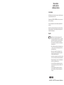
1
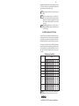
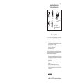
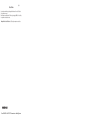
Worm Gear Reducers
Installation, Lubrication
and Maintenance Instructions
Selection Information
Read ALL instructions prior to operating reducer. Injury to personnel or reducer failure may be caused
by improper installation, maintenance or operation.
Written authorization from GROVE GEAR / ELECTRA-GEAR is required to operate or use reducers in
man lift or people moving devices.
Check to make certain application does not exceed the allowable load capacities published in the
current catalog.
Buyer shall be solely responsible for determining the adequacy of the product for any and all uses to
which Buyer shall apply the product. The application by Buyer shall not be subject to any implied
warranty of fitness for a particular purpose.
Safety Alert
WARNING • For safety, Buyer or User should provide protective guards over all shaft
extensions and any moving apparatus mounted thereon. The User is responsible
for checking all applicable safety codes in his area and providing suitable guards.
Failure to do so may result in bodily injury and/or damage to equipment.
•
Hot oil and reducers can cause severe burns. Use extreme care when removing
lubrication plugs and vents.
•
Make certain that the power supply is disconnected before attempting to service
or remove any components. Lock out the power supply and tag it to prevent
unexpected application of power.
•
Reducers are not to be considered fail safe or self-locking devices. If these
features are required, a properly sized, independent holding device should be
utilized. Reducers should not be used as a brake.
•
Any brakes that are used in conjunction with a reducer must be sized or positioned
in such a way so as to not subject the reducer to loads beyond the catalog rating.
•
Lifting supports including eyebolts are to be used for vertically lifting the gearbox
only, with no other associated attachments or motors.
•
Use of an oil with an EP additive on units with backstops may prevent proper
operation of the backstop. Injury to personnel, damage to the reducer or other
equipment may result.
• Overhung loads subject shaft bearings and shafts to stress which may cause
premature bearing failure and/or shaft breakage from bending fatigue, if not
sized properly.
Phone: 800.894.0412 - Fax: 888.723.4773 - Web: www.clrwtr.com - Email: [email protected]
Page 2
CAUTION
• Test run unit to verify operation. If the unit tested is a prototype, that unit must be
of current production.
• If the speed reducer cannot be located in a clear and dry area with access to
adequate cooling air supply, then precautions must be taken to avoid the ingestion
of contaminants such as water and the reduction in cooling ability due to exterior
contaminants.
• Mounting bolts should be routinely checked to ensure that the unit is firmly
anchored for proper operation.
Important Information
In the event of the resale of any of the goods, in whatever form, Resellers/Buyers will include the following
language in a conspicuous place and in a conspicuous manner in a written agreement covering such sale:
The manufacturer makes no warranties or representations, express or implied, by
operation of law or otherwise, as to the merchantability or fitness for a particular
purpose of the goods sold hereunder. Buyer acknowledges that it alone has determined that the goods purchased hereunder will suitably meet the requirements of
their intended use. In no event will the manufacturer be liable for consequential,
incidental or other damages. Even if the repair or replacement remedy shall be
deemed to have failed of its essential purpose under Section 2-719 of the Uniform
Commercial Code, the manufacturer shall have no liability to Buyer for consequential
damages.
Resellers/Buyers agree to also include this entire document including the warnings above in a conspicuous place and in a conspicuous manner in writing to instruct users on the safe usage of the product.
This instructions manual should be read together with all other printed information such as catalogs, supplied by
Grove Gear / Electra-Gear.
General Operation
1. Run the motor which drives the reducer and check the direction of reducer output rotation. Consult
motor nameplate for instructions to reverse the direction of rotation.
2. Attaching the load: On direct coupled installations, check shaft and coupling alignment between
speed reducer and loading mechanism. On chain/sprocket and belt/pulley installation, locate the
sprocket or pulley as close to the oil seal as possible to minimize overhung load. Check to verify that
the overhung load does not exceed specifications published in the catalog.
3. High momentum loads: If coasting to a stop is undesirable, a braking mechanism should be provided
to the speed reducer output shaft or the driven mechanism.
CAUTION
The system of connected rotating parts must be free from critical speed,
torsional or other type vibration, no matter how induced. The responsibility
for this system analysis lies with the purchaser of the speed reducer.
Phone: 800.894.0412 - Fax: 888.723.4773 - Web: www.clrwtr.com - Email: [email protected]
Installation
Page 3
1. Mount the unit to a rigid flat surface using grade 5 or higher fasteners. The mounting fasteners should
be the largest standard size that will fit in the base mounting hole. Shim as required under flange or
base feet which do not lie flat against the mounting surface.
2. For shipment, pipe plugs are installed in the unit and a vent plug is packed separately.
After mounting the unit in position, remove the appropriate pipe plug and install the vent
plug in the location shown on page 5. On double reduction units both the primary and the
secondary must be vented. Failure to vent the unit can cause premature seal wear or
loss of seal and oil. These conditions are not covered by warranty. Check for correct oil
level. Contact the Factory for level and vent recommendations on non-standard mounting
positions.
3. Connect motor to speed reducer.
Depending upon gear geometry and operating conditions worm gear reducers may or may not backdrive. Use of a brake or external holding device is required if any evidence of backdriving is not desired.
Special consideration should be given to high inertia loads connected to the output shaft. Consult the
factory for further details.
WARNING DO NOT CHANGE MOUNTING POSITIONS WITHOUT CONTACTING FACTORY.
Altering the mounting position may require special lubrication provisions which
must be factory installed.
CAUTION Do not operate the reducer without making sure it contains the correct amount
of oil. Do not overfill or underfill with oil, or injury to personnel, reducer or other
equipment may result.
CAUTION A unit cannot be used as an integral part of a machine superstructure which would
impose additional loads on the unit other than those imposed by the torque
being transmitted either through a shaft-mounted arrangement, and any shaft
mounted power transmitting device. (e.g., sprockets, pulleys, couplings)
CAUTION For safe operation and to maintain the unit warranty, when changing a factory
installed fastener for any reason, it becomes the responsibility of the person
making the change to properly account for fastener grade, thread engagement, load,
tightening torque and the means of torque retention.
Lubrication - Standard and
WASHGUARD® / Platinum Units
All standard reducers ordered from Factory are filled with Mobil Glygoyle 460 polyglycol (PAG) lubricant
or equivalent suitable for continuous option within a -10° F to 120° F ambient temperature range. Double
and triple reduction units have separate oil sumps and must be filled/checked independently. Prior to
startup, verify that the oil is at the level shown on page 6. Lubricant type is stamped on all nameplates.
Phone: 800.894.0412 - Fax: 888.723.4773 - Web: www.clrwtr.com - Email: [email protected]
Page 4
Change Intervals: Standard compounded lubricants (non-synthetic) should be changed every six months
or 2500 operating hours, whichever comes first. Factory installed synthetic lubricants should be changed
only when performing maintenance that requires gearbox disassembly.
CAUTION Oil should be changed more often if reducer is used in a severe environment (i.e. dusty,
humid).
CAUTION In the Food and Drug Industry (including animal food), consult the lubrication
supplier for recommendation of lubricants which are acceptable to the Food and Drug
Administration and/or other authoritative bodies having jurisdiction. Factory supplied
PAG oil is acceptable for incidental food contact (NSF H1) for use in and around food
processing areas.
CAUTION Do not mix different oils in the reducer. Grove Gear / Electra-Gear reducers are
shipped standard with PAG lubricant – this lubricant is not compatible with conventional
mineral or PAO synthetic oils.
Special Lubrication Requirements - Size 818 and Larger
Units shipped from Factory are assembled to properly lubricate all internal components based on a specific assumed mounting orientation. If a size 818 or larger unit will be mounted in an orientation different
from its original intension, as shown in product catalog, or run with sustained input speeds less than 1200
RPM, it should be specified with the order. The unit can then be modified to assure proper lubrication.
The precision-made gears and bearings in Grove Gear / Electra-Gear Speed Reducers require high-grade
lubricants of the proper viscosity to maintain trouble-free performance. All standard reducers ordered
from the factory are filled with ISO viscosity grade 460 polyglycol (PAG) lubricant. If oil needs to be
added or changed, ONLY compatible polyglycol lubricants should be used. Contact the factory for
more information.
Oil Capacities (ounces) - Standard Units
Mounting
Position
UNIT SIZE
813815818 821824 826830 832842 852 860 870*
880* 8100*
Worm Over
4
12 12 20 24 40 56 72 112 188 312
560
768
1152
Worm Under
8
16 20 28 40 60 84 108 152 304 328
524
820
1280
Vertical Output
4
16 16 28 32 48 68 88 128 248 320
332
460
640
Vertical Input
4
16 16 24 32 48 72 92 128 248 325
584
800
1200
Extended Bearing
N/AN/AN/A N/AN/A N/AN/A 8
12 17 27
640
1008
1632
Worm Over
on Secondary Unit of Double
Reduction
N/AN/AN/A N/AN/A N/AN/A 192 308 320 485
805
114
1716
14 18 26 32 50 78 98 N/A N/A N/A N/A
N/A
N/A
Stainless Steel +
WASHGUARD® - All
Mounting Positions
6
CAUTION Always check for proper oil level after filling. Capacities vary somewhat with model and
mounting position. Oil should rise to bottom edge of level hole. Do not overfill.
Phone: 800.894.0412 - Fax: 888.723.4773 - Web: www.clrwtr.com - Email: [email protected]
Page 5
Standard Gear Reducer Mounting Positions
& Vent Plug, Level and Drain Locations s
VENT
VENT
VENT
VENT
LEVEL*
LEVEL
LEVEL
LEVEL
DRAIN
DRAIN
Worm Over
Vertical Output
VENT
VENT
LEVEL
DRAIN
Worm Under
DRAIN
(All primary units have
their own oil level.)
DRAIN
Double Reduction Worm-Worm
LEVEL
DRAIN
Vertical Input
* Size 842 - 860 (far side plug).
Note: High oil level applies to all size 842 & larger
secondary & tertiary units regardless of primary
unit type.
s Does not apply to Stainless Steel, WASHGUARD® or units with Enviroseal option.
Maintenance - Standard Units
Your Grove Gear / Electra-Gear reducer has been tested and adjusted at Factory. Dismantling or
replacement of components must be done by Grove Gear / Electra-Gear to maintain the warranty.
1.
2.
3.
4.
Frequently check the oil level of the reducer. If oil level is low, (refer to reducer vent and level
position chart) add proper lubrication through the filler plug until it comes out the oil level plug.
Inspect vent plug often to insure it is clean and operating.
Always check for proper oil level after filling. Do not overfill or underfill with oil, or injury to
personnel, reducer, or other equipment may result.
Do not mix different oils in the reducer.
Seals: The Grove Gear / Electra-Gear line of speed reducers utilizes premium quality seals which are the
state-of-the-art in sealing technology. Seals are, however, a wear item and eventually need to be replaced.
Replacement can be easily accomplished by following the steps below:
1.
2.
3.
4.
5.
6.
Remove the worn seal without damaging the shaft surface or the seal bore. This can be done by
drilling a .062 diameter hole in the seal casing (being careful not to drill into the bearing behind
the seal). Install a #10 sheet metal screw into the hole and pry out the seal.
Clean the seal bore of sealant.
Before installing the new seal, use electrical tape to cover any keyways on the shaft to prevent
seal lip damage.
Grease the seal lips with bearing grease and apply a sealant to the seal bore.
Slide the seal into the shaft being careful not to fold the inner lip over on any shaft steps.
Press the seal into its bore with a sleeve that presses on the seal casing, being careful to keep
the seal square in its bore.
Phone: 800.894.0412 - Fax: 888.723.4773 - Web: www.clrwtr.com - Email: [email protected]
Class of Service
Page 6
Load conditions must be within cataloged ratings published in the current Grove Gear / Electra-Gear
Catalog (available upon request).
Published ratings assume lubrication with ISO 460 viscosity grade polyglycol (PAG) oil. Contact Factory
for ratings when an alternate lubricant is used.
Warranty From Grove Gear / Electra-Gear - See 8050 catalog for warranty terms and conditions.
Phone: 800.894.0412 - Fax: 888.723.4773 - Web: www.clrwtr.com - Email: [email protected]
Page 7
PARTS LIST
7
5
MODEL B813-8100
6
11
(Basic Unit Components)
SINGLE REDUCTION
10
28
12
27
136
3
17
129
132
23
26
21
4
134
2
133
2
26
25
26
132
130
8
23
7
22
13
18B
17
18A
6
22
131
18B
18A
1
132
2
20
16
15
24
14
19
ASIC SINGLE REDUCTION UNIT
B
(B-STYLE)
ITEM # DESCRIPTION
1 HOUSING
2 PIPE PLUG
3 VENT PLUG
4 SPLASH GUARD
5 INPUT CAP
6 O-RING
7 HEX HEAD CAP SCREW
8 INPUT OIL SEAL
9 INPUT BEARING (cup and cone for
842 and larger units)
10 INPUT BEARING (cup and cone for
842 and larger units)
*11 RETAINING SCREW
12 INPUT WORM SHAFT
13 OUTPUT COVER - OPEN
14 OUTPUT COVER - CLOSED
15 O-RING
16
17
18
19
♣ 20
♣ 21
22
23
♣ 24
*25
26
27
28
UTPUT COVER SHIM (as required)
O
OUTPUT OIL SEAL
OUTPUT BEARING (18A. CONE,
18B. CUP)
HEX HEAD CAP SCREW
OUTPUT SHAFT - SINGLE
OUTPUT SHAFT - DOUBLE
GEAR SPACER
GEAR KEY (only used on size 826
and larger units)
OUTPUT GEAR
INPUT COVER
KEY - OUTPUT EXTENSION
KEY - INPUT EXTENSION
NAMEPLATE
(supplied only when mounting
position involves a vertical shaft)
*129 OUTPUT COVER - CLOSED
*130 OUTPUT COVER - OPEN
*131 OUTPUT BEARING GREASE
RETAINER
132 GREASE FITTING
133 SEALED BALL BEARING
(only used on size 818 thru 826
units)
♦134 INPUT COVER
♦136 INPUT BEARING GREASE RETAINER
* ONLY USED ON SIZE 842 AND LARGER
UNITS
♦ ONLY USED ON SIZE 830 AND LARGER
UNITS
♣ SUPPLIED ONLY AS OUTPUT ASSEMBLY
ON 813 THROUGH 824 UNITS
VERTICAL SHAFT REQUIRED PARTS
Complete information is available online
Continued on next page
Phone: 800.894.0412 - Fax: 888.723.4773 - Web: www.clrwtr.com - Email: [email protected]
Page 8
PARTS LIST (cont’d)
QUILL MOTOR FLANGE UNIT
(BMQ-STYLE)
40 QUILL MOTOR FLANGE
41 INPUT OIL SEAL
42 HEX HEAD CAP SCREW (flange to
housing)
43 RETAINING RING - SHAFT
*44 RETAINING RING - HOUSING
45 QUILL INPUT SHAFT
46 KEY - INPUT
47 HEX HEAD CAP SCREW (motor to
flange)
51
52
53
54
♣ 55
56
57
♣ 58
59
5
111
115
116
117
118
119
120
MODEL BM813-8100
6
43
10
45
5
EX HEAD CAP SCREW
H
(flange to housing)
COUPLING KEY - REDUCER SHAFT
SETSCREW - REDUCER SHAFT
COUPLING GEAR REDUCER SHAFT
COUPLING SLEEVE
SETSCREW - MOTOR SHAFT
COUPLING GEAR - MOTOR SHAFT
COUPLING KEY - MOTOR SHAFT
HEX HEAD CAP SCREW
(motor to flange)
PLASTIC PLUG
112
113
114
LONG MOTOR FLANGE AND
COUPLING KIT (BM-STYLE)
110 “C” FACE MOTOR FLANGE
HOLLOW OUTPUT SHAFT UNIT
(H-STYLE)
7
OUTPUT COVER
OUTPUT OIL SEAL
OUTPUT BEARING (53A. CONE,
53B. CUP)
GEAR SPACER
OUTPUT SHAFT
SETSCREW
GEAR KEY (only used on size 826
and larger units)
OUTPUT GEAR
OUTPUT KEY
119
(Refer to Single Reduction
Basic Unit Components)
110
111
46
112
114
113
115
117
116
118
44
41
120
47
40
42
52
MODEL BMQ813-8100
(Refer to Single Reduction Basic Unit
Components)
56
59
53B
53A
54
55
57
58
ForthefullWormGear
Reducer Installation,
Lubrication and
Maintenanceinstructions,
Visit Grove Gear website.
54
53B
16
15
53A
HOLLOW SHAFT MODELS
H, HM, HMQ
(Refer to Single Reduction
Basic Unit Components)
51
52
19
A Regal Brand
Phone: 800.894.0412 - Fax: 888.723.4773 - Web: www.clrwtr.com - Email: [email protected]