1
UNDERCOVER LED KIT USER MANUAL
CONTENTS
LED LIGHTHEAD x 2pcs
EXTENSION CABLE
LED FLASHER & CABLE
GASKET x 2pcs
SCREW x 4pcs
INSTALLATION
Corner Light Assembly
1.
2.
3.
4.
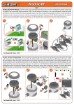
Remove Corner/Head/Tail light from vehicle.
Select location to mount LED lighthead.
Drill 1 inch diameter hole.
Insert lighthead into hole and secure with
supplied sheet metal screws.
NOTE: Rotate lighthead to achieve optimum
effect as vehicle reflectors may vary.
WARNING: Make sure the LED lighthead does
not interfere with the operation of vehicle lights.
Mounting screw holes
1 inch dia. hole
to lighthead
Gasket
LED Lighthead
FP#
Supplied sheet metal screw
To +VDC (fuse @ 5A)
To Chassis Ground
RED
BLACK
Flash Patterns
0
Random
1
Single (split)
2
Double (split)
3
Quad (split)
4
Quint (split)
5
Mega (split)
6
Ultra (split)
7
Single-Quad (split)
8
Single H/L (split)
For Simultaneous or Alternating Flash
9
Single (all)
Group1 Heads: (Wiring- WHITE connected to RED) will flash together
Group2 Heads: (Wiring- WHITE not connected to RED) will flash together
*Group1 Heads will alternate with Group2 Heads*
10
Double (all)
11
Quad (all)
12
Quint (all)
13
Mega (all)
14
Ultra (all)
15
Single-Quad (all)
16
Single H/L (all)
17
Steady 2 (CA)
18
Steady 4 (all)
For Synchronization & Flash Patterns
Connect YELLOW wires of all Kits together for synchronization
*All kits must be set at the same pattern
Momentarily apply +VDC to YELLOW wire:
.once for next pattern
.quickly three times for reset
NOTE: This unit may not be factory set at FP# 0
*SPLIT = Head1 alternate Head2
*ALL = Head1 & 2 Simultaneous
090320
WARNING: Do not connect lighthead directly to
power. It will cause damages and void warranty.
YELLOW
WIRING
(illustration of wiring 2 kits together)
In this configuration, Unit1 heads will alternate with Unit2 heads.
YELLOW
Unit2 Controller
Unit1 Controller
RED
BLACK
BLACK
EXTENSION CABLE
EXTENSION CABLE
to GND
to GND
ON/OFF
5A FUSE
(user-supplied)
CHASSIS
GROUND
NOTE: Illustration not to scale.
WIRING
(illustration of wiring to existing strobe cables)
In this configuration, existing strobe extension cables are used to facilitate installation.
CONTROLLER
ŔŕœŐŃņġ
őŐŘņœġŔŖőőōŚġ
Yellow
to (+)
1. Disconnect strobe
extension cables from
strobe power supply.
to
GND
2. Connect LED Kit
connectors to strobe
extension cables.
3. Remove & Disconnect Strobe
bulbs from extension cables.
STROBE BULB
EXTENSION CABLE
(already in vehicle)
4. Insert & Connect LED Ligtheads
to strobe extension cables.
NOTE: The wire colors of the LED Kit does not have to match the wire colors of the strobe extension cables.