Transcript
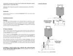
USER MANUAL
LFW408A LED FLASHER
SPECIFICATIONS
Input Voltage: 12VDC
Output Current: 3Amps per Group
Number of Groups: 4
Number of Outlets: 2 per Group
Flash Patterns: 12
RED
GROUP 3
connector
RED
GREEN & WHITE
to LED -VDC
When LED lightheads don’t function (inactive), check status of “ERROR LED” indicator.
If ERROR LED is off, check that polarity (+VDC & -VDC) wires of the CONTROL or the GROUPS are not reversed.
If ERROR LED is on, check that polarity (+VDC & -VDC) wires are not touching each other (short circuit).
If there is no short circuit, check that the current of connected lightheads do not exceed 3Amps/GROUP.
FLASH PATTERN INDICATOR
GROUP 1 GROUP 2 GROUP 3 GROUP 4
to LED +VDC
RED
RED
BLUE & WHITE
GROUP 4
connector
to LED -VDC
CONTROL
ON/OFF
PURPLE
WHITE
LOW
POWER
GREEN
BLUE
LED SWITCH
PATTERN
INDICATOR
ORANGE
RED
to LED -VDC
WHITE & BLACK
to LED -VDC
RED
RED
to LED +VDC
WHITE & RED
RED
RED
to LED +VDC
YELLOW
GROUP 2
connector
GROUP
CHANGE
AUXILIARY
ACTIVATION
PATTERN
CHANGE
BLACK
TO +VDC
TO-VDC
RED
GROUP 1
connector
ERROR
INDICATOR
BLACK
WARNING: All user-supplied extension wires, that
connect to +VDC & -VDC terminals,
must be sized to supply at least 125%
of the maximum operating current.
The length of the wires determines
the size needed: .1 to 7 ft. use 18AWG wire.
.7 to 14 ft. use 16AWG wire.
.14 to 25 ft. use 14AWG wire.
.25 to 35 ft. use 12AWG wire.
GROUP PATTERNS
A. (G1&G2) alt (G3&G4)
B. (G1&G3) alt (G2&G4)
C. (G1&G4) alt (G2&G3)
D. G1 alt G2 alt G3 alt G4
E. G1&G2&G3&G4
Momentarily apply +VDC
once for next pattern
FP#FLASH PATTERNS
0. Random
1. Steady
2. Single
3. Mega
4. Double
5. Triple
6. Quad
7. Quint
8. 8 Flash
9. Single-Quad
10. Single H/L
11. Single-Triple-Quint
Momentarily apply +VDC:
- once for next pattern
- quickly 3 times to FP#0
OPTIONAL CONNECTIONS
GREEN - apply to +VDC for low power
ORANGE - for LED switch
BLUE - apply to +VDC to activate
NOTE: The BLUE wire can be connected
to other switches such as siren, so
that it can be activated when
siren is switched on.
061121
to LED +VDC
TROUBLE SHOOTING