1
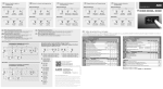
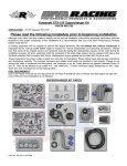
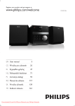
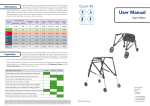
Quick start
1 Wiring
AKO-80077
Electronic
expansion
valve*
Emergency
power supply
12 Vdc input +
the controller according to the diagram
1 inConnect
the ''wiring'' section.
Configure the rFt, EM and SH parameters
2 according
to the indications in the “Start up
Mesh
24
Tr+
RS485
Tr- MODBUS
GND
2 Initial configuration
Prior to start-up, it is vital to configure the following parameters:
AKO-145601
* Select the valve model connected via the EM
parameter.
The table shows the equivalence of terminals for
the most common models.
A+
AB+
B-
IN
24 V
+
0
115
230
configuration”.
0
115 V
230 V
Operation
ºC
%
SET
COM
NO
S1
Com.
Probe 1
Temperature
AKO-15606
PRG
+5V
Signal
Com.
ON /
OFF
Max. 25 m
(AKO-15586)
bar
A+
AB+
B-
Danfoss
ETS
White
Black
Red
Green
Power supply
valve
Probe 2 Suction
pressure
AKO-15571
Red +5V
Green signal
Black Common
Alco
EX5/6
White
Black
Brown
Blue
Carel
Alco
Yellow
White
Brown
Green
Sporlan
SEI / SEH
Black
White
Red
Green
Liquid
solenoid
valve
AKO-D141xx Connection/disconnection
should be made via a contact
or potential free relay.
SET
RFT: Select the type of refrigerant gas used in the installation from among the following compatible gases:
0: R-22
4: R-410A
8: R-HFO1234ze
12: R-507A
1: R-134A
5: R-717
9: R-744
2: R-404A
6: R-23
10: R-407A
3: R-407C
7: R-507C
11: R-407F
EM: Select the expansion valve model installed from
among the following compatible models:
1: Danfoss ETS 12.5 / 25B
3: Danfoss ETS 100B
5: Danfoss ETS 400
7: Alco EX5
9: Alco EX7
11: Alco EX8 (500 step/sec)
13: Spolarn SEI 1.5~20
15: Spolarn SEI 100
17: Carel E2V
2: Danfoss ETS 50B
4: Danfoss ETS 250
6: Alco Ex4
8: Alco Ex6
10: Alco EX8 (330 step/sec)
12: Spolarn SEI 0.5~11
14: Spolarn SEI 30
16: Spolarn SEI 175
Keypad
PRG key: Pressing it for 5 seconds accesses the parameters
programming menu.
Pressing it twice allows the regulation to be restarted in the event
of an alarm. In the programming menu, you may return to level 1.
UP N key: In the programming menu, you may scroll around the
different levels, or during the setting of a parameter, change its value.
DOWN Q key: In the programming menu, you may scroll around
the different levels, or during the setting of a parameter, change its
value.
SET key: Allows the displayed value to be changed (overheating,
suction pressure, expansion valve opening or temperature) (only if
the DM parameter = 0).
The programming menu allows you to move around the different
levels and accept changes. Pressing it for 5 seconds exits the
programming menu.
Adjustment of parameters
Using the programming menu, you will be able to configure the
various parameters in order to adapt the controller's operation to
the needs of its installation.
In order to access the programming menu, press the PRG key for 5
seconds, or until the message ''PwD'' is displayed. Using the N and
Q keys enter the password (programmed into the PSS parameter)
and press SET. Once entered correctly, the password will not be
requested again for 30 minutes.
SH: Configure the overheating set point
GB 1456H012 Ed.01
5"
Description
ºC
bar
Quick guide
1
2
Password
request
ºC
PRG
bar
3
4
SUBIR key
SET
IN PROGRAMMING
7
Level 1:
Menus
Level 2:
Parameters
SET key
BAJAR key
Tel.: +34 902 333 145
Fax: +34 938 934 054
www.ako.com
351456012 REV.00 2015
Avda. Roquetes, 30-38
08812 • Sant Pere de Ribes.
Barcelona • Spain.
We reserve the right to supply materials that might vary slightly to those described in
our Technical Sheets. Updated information is available on our website
AKO-145601
SET
ºC
bar
1: The display shows the overheating value.
2: The display shows the suction pressure value (Probe 2).
3: The display shows the valve opening percentage.
4: The display shows the temperature value.
5: An alert is active
6: The display shows the temperature value in ºC.
7: The display shows the suction pressure value in bar
8: The opening degree of the valve has been configured manually
(Cor)
ºC
bar
Change
parameter
Change
menu
Level 3:
Values
ºC
bar
ºC
AKO ELECTROMECÁNICA , S.A.L.
SET
Accept
changes
6
8
PRG
bar
Change value
ºC
PRG key
ºC
bar
5
ºC
Enter
password*
bar
bar
Change
value
Accept
changes
ºC
bar
SET
PRG
5" Press the SET button for 5 seconds to exit programming. If no
SET
key is pressed for 3 minutes, the controller will exit
programming.
*The default value of the password is 5. This may be changed using the
PSS parameter.
Table of parameters
Warnings
Maximum pressure alarm in probe 2 0: Deactivated
1: Automatic reset
2: Manual reset
Mps Maximum pressure alarm activation value
Mpt Maximum pressure alarm turn-on delay time
MpC Maximum pressure alarm deactivation time
HSM
Maximum overheating alarm
1: Automatic reset
LPM
(K)
(Min.)
(K)
0: Deactivated
2: Manual reset
FPS Maximum freeze alarm activation value
FPT Freeze alarm turn-on delay time
FPC Maximum freeze alarm deactivation time
(ºC/ºF)
(Sec.)
(ºC/ºF)
Lower pressure alarm in probe 2 0: Deactivated
1: Automatic reset
2: Manual reset
LPS Lower pressure alarm activation value
LPT Lower pressure alarm turn-on delay time
LPC Lower pressure alarm deactivation time
GROUP 2
Description
0: Bar 1: Psi
pu Pressure units
2.Pr
0: ºC
1: ºF
Tu Temperature units
1
2
0.1
1
0.1
9
1
8
99.9
15
99.9
0
0
2
10.0
1
7.0
30
3
27
40.0
600
37.0
0
0
2
-100
5
-97
0
30
3
392
200
392
0
1
2
-1
5
0.7
0
5
0.3
25
200
25.3
UrL Lower expansion valve opening limit
Ft Reading delay for probes (S1 and S2)
COR Lower expansion valve forced opening value
(bar/psi)
(Sec.)
(bar/psi)
Values Min.
0
0
Def. Max.
0
1
0
1
Selection of expansion valve model connected
1: Danfoss ETS 12.5 / 25B 2: Danfoss ETS 50B 3: Danfoss ETS 100B
4: Danfoss ETS 250
5: Danfoss ETS 400
6: Alco EX4
EM
7: Alco EX5
8: Alco EX6
9: Alco EX7
10: Alco EX8 (330 s/s) 11: Alco EX8 (500 s/s) 12: Spolarn SEI 0.5~11
13: Spolarn SEI 1.5~20 14: Spolarn SEI 30
15: Spolarn SEI 100
16: Spolarn SEI 175
17: Carel E2V
1
1
17
TST Total steps for expansion valve*
DSP Expansion valve speed*
0
0
260
250
999
999
(%)
(Sec.)
(%)
0
0.1
0.0
0
1
OFF
100
10.0
100
Display mode:
0: Displays options 1 to 4 sequentially
1: Overheating value (ºK)
2: Suction pressure value (Probe 2)
3: Valve opening (%)
4: Temperature value (Probe 1)
5: Overheating set point
DM
0: Deactivated
2: Manual reset
HSS Maximum overheating alarm activation value
HST Maximum overheating alarm turn-on delay time
HSC Maximum overheating alarm deactivation time
Freeze alarm
FPM
1: Automatic reset
(bar/psi)
(Min.)
(bar/psi)
0
Level 2
MpM
Level 1
Level 2
Level 1
Using the unit not observing the manufacturer's instructions may alter the appliance's
The equipment's operation functions are divided into 3 different groups.
The Def. column indicates the default parameters set in the factory. Temperature values are expressed in ºC. (Equivalent temperature in ºF) and the pressure values in bar (equivalent safety requirements. Only probes supplied by AKO should be used for the appliance to
operate correctly.
pressure in psi).
The unit should be installed in a place protected from vibrations, water and corrosive
gases, where the ambient temperature does not exceed the values indicated in the
technical data.
For the reading to be correct, the probe should be used in a place without heat
GROUP 1
GROUP 3
influences apart from the temperature you want to measure or control.
Description
Values Min. Def. Max.
Description
Values Min. Def. Max.
(K)
0.5
10
30
0
5
999
SH Overheating set point
pss Parameter access password
The probe and its cable should NEVER be installed in a conduit together with power
1.Pr
3.Pr
(%)
0
50
100
supply, control or feeder cables.
or Initial opening for valve start up
Type of refrigerant gas used: 0: R-22 1: R-134A 2: R-404A
1
0
12
4: R-410A 5: R-717
6: R-23 7: R-507C
rft 3: R-407C
(Sec.)
0
5
300
ort Duration of initial start up opening
The power supply circuit should be equipped with a switch for its disconnection of at least
8: R-HFO1234ze 9: R-744 10: R-407A 11: R-407F 12: R-507A
0.1
3
99.9
pro Proportional gain
2A, 230V, situated near the appliance. The cables are inserted into the rear part and should
(bar/psi)
-1
15
99
PSH Pressure probe range (Maximum)
(Sec.)
0
120 999
be H05VV-F or H05V-K type. The section to be used will depend on local regulations, but
int Integral time
(bar/psi)
-1
-1
99
PSL Pressure probe range (Lower)
should not under any circumstances be less than 1 mm².
(Sec.)
0
30
999
der Derivative time
(bar/psi) -9.9
0
9.9
PSO Pressure probe calibration (S2)
The cables for wiring the relay contacts should have a section of between 1 mm2 and 2.5 mm2
Lower overheating alarm
0: Deactivated
0
1
2
lsM
(ºC)
-19.9
0
19.9
TSO Pressure probe calibration (S1)
1: Automatic reset
2: Manual reset
and wire for the one in common should always have a section of 2.5 mm2. Using of halogen(K)
0.5
3
30
lSS Lower overheating alarm activation value
free cables is recommended.
(%)
0.1
OFF
9.9
JCR Expansion valve opening speed limit
(Sec.)
1
15
300
LSt Lower overheating alarm turn-on delay time
Probes 1 and 2 should be installed as close as possible to the evaporator output. There
Maximum
expansion
valve
opening
limit
(%)
0
100
100
UrH
(K)
1
5
30.5
lsC Lower overheating alarm deactivation time
should not be any device between them (valves, peep-holes etc.) that could alter the reading.
CID Communication direction
CSP Communication speed
INI Initial settings (enter password and press SET)
(BPSx100)
0
1
14
1
48
0
1
96
0
254
384
999
* The TST and DSP parameters are adjusted automatically when the expansion valve
model is selected. They should only be changed by qualified staff. AKO is not
responsible for any damage that may be inflicted on the installation.
EXPANSION
VALVE
LIQUID
SOLENOID
AKO-145601
ºC
%
bar
PRG
AKO-D141xx
EVAPORADOR
SET
S1
S2
SET
Messages
Description
Problem in the pressure sensor
Probe 1 not connected
Crossed temperature probe
Maximum Operation Pressure (MOP) alarm
Lower Operation Pressure (LOP) alarm
Maximum overheating alarm
Lower overheating alarm
Frost detection alarm
Regulation stopped by external thermostat (ON/OFF Input)
Expansion valve initialisation
Valve closing underway due to fault in the electricity supply (emergency power
CLE supply required)
PS
TSD
TsC
MOP
LOP
HS
LS
FRA
STP
CAL
IMPORTANT: In the event of an alarm or fault in any of the probes, the
controller closes the liquid solenoid and expansion valve until the problem is
solved.
For further information, refer to the user manual available on
our website: www.ako.com