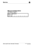
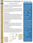
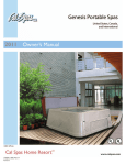
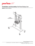
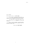
1
C. M
.
S.
Te c nol ogi e
SUBMERSIBLE AERATORS
Wastewater Treatment Aeration & Mixing
INDEX
1.
General information
Page 03
1.1
Use of symbols
03
1.2
General conditions
03
1.3
Example of data plate
04
1.4
Operating instructions
05
2.
Safety
05
3.
Description of the product and use
06
3.1
Technical, characteristics, function and use
06
3.2
Marginal notes to take into consideration
07
4.
Handling and storage
08
5.
Installation
08
5.1
Preliminary inspections
08
5.2
Electrical connections
10
6.
Directions of use and maintenance
11
6.1
Start
11
6.2
Running and inspections
11
6.3
Maintenance
12
6.4
Out of use/Inactivity
14
7.
To take out of use and dismount
14
8.
Warranty
14
9.
Causes of irregular function - troubleshooters
15-16
Nomenclature / Typical sections
17-28
1
SUBMERGED RADIAL AERATOR
TYPES SC
and SC/L
The picture is illustrative and not binding
for S.C.M. Tecnologie
User’s manual
2
1. GENERAL INFORMATION
1.1 USE OF SYMBOLS
The instructions in this manual concerning safety are marked by this
symbol. Your disrespect and failure to follow these instructions might
expose staff to health risks.
Furthermore the instructions in this manual concerning electrical hazards
are marked by this symbol. Your disrespect and failure to follow these
instructions might expose staff to risks of electrical nature.
ATTENTION
The instructions preceded by this word concern the main
recommendations for correct installation, operation, preservation and
dismountation of the electric aerator itself. To ensure safe and reliable
management of the electric aerator throughout its useful life, you must
follow all indications in this manual.
Read the use and maintenance manual.
1.2 GENERAL CONDITIONS
Check that the items indicated on the consignment note correspond to those you actually
received and that these have not been damaged.
Before you proceed working on the aerator, please become fully familiar with all the
instructions given in the supplied documentation.
The manual and all the supplied documents, including a copy of the data plates, form an
integral part of the aerator in use. For example, the additional data plates can be attached
to the user's manual.
No part of these documents may be duplicated in any form unless prior authorization has
been obtained from the manufacturer.
3
1.3 EXEMPLIFICATION OF DATA PLATE
A
B
C
E
F
H
D
I
L
G
A
Type of equipment and serial number
B
Date
C
Type of equipment
D
Nominal mains voltage
E
Maximum absorbed current
F
Type of connection
G
Maximum power absorption
H
Frequency
I
Rotation speed
L
Class of motor protection
The manufacturer reserves his right to modify the technical characteristics without
previous notice.
4
1.4 OPERATING INSTRUCTIONS
Become thoroughly familiar with the instructions in the documents consigned with the
aerator. This will enable you to work in complete safety and to obtain the best performance
the aerator is capable to offer.
The following instructions apply to the standard version of the aerator in normal conditions.
Special versions, shown by the product code, may not fully comply with the indications
herein (when necessary, the manual will be supplied with additional information).
In correspondence with our policy of constant development and improvement of our
products, the data in the documentation and the product itself may be subjects to
modification without further notice from the manufacturer.
The disrespect of all the instructions in this manual or an inappropriate use or unauthorized
modifications to the aerator unit will void all forms of guarantee, while the manufacturer
shall not be held responsible for any damages of any kind to persons, animals or property.
2. SAFETY :
Before proceeding with any form of operation on the product, always
make sure that the electrical parts of the system that you work on are
not connected to electrical power.
The submerged radial aerator described in this manual is for industrial
use, for building sites or permanent use at home. As such, the maintenance
of the product in form of service, reparation or dismountation must be
carried out by specialized staff possessing appropriate qualifications and
equipped with adequate tools. The handling, installation and management
of the product may also be carried out by non-specialized staff on the
conditions that they have become fully familiar with the contents of this
manual and any other documentation supplied with the product.
Always comply with all safety accident-prevention and anti-pollution
instructions in the manual during each individual operation, together
with all the more restrictive local provisions in merit.
5
Since the nature of the aerated liquids varies, it may be necessary to
wear appropriate clothing to protect your skin from contact with the
same.
For safety reasons and to ensure compliance with the warranty conditions,
the purchaser is forbidden to use the aerator should this become faulty
or in the event of a sudden variation in the performances of the aerator
itself.
Installation must be such as to prevent accidental contacts which could
represent a hazard for persons, animals and property.
Inspections and servicing procedures must be carried out to prevent all
forms of risk following malfunction of the aerator unit.
Consult the “Handling and storage“ chapter for safe handling and storage.
3. DESCRIPTION OF THE PRODUCT AND USE :
3.1 TECHNICAL CHARACTERISTICS, CHARACTERISTICS, FUNCTION
AND USE: (SEE PICTURE AND TABLE ON PAGES 25/26)
The SC submerged aerators are an extremely flexible and versatile airing system for the
t r e a t m e n t o f wa s t ewa t e r a n d w h e n eve r m i x i n g w i t h a i r i s r e q u i r e d
Elevated oxygen transfer values, low noise levels, high reliability, low costs and ease of
installation are just some of the advantages that our SC submerged aerators offer.
Moreover, they can be powered by atmospheric air, pure oxygen enriched air or by pure
oxygen alone without having to install complicated and expensive air diffusion systems.
The submersed aerator consists of a submerged motor which activates an impeller. The
rotation of the impeller creates a void in the compartment of the same, thus allowing
aspiration of air from a special aspiration chamber.
The air and liquid are mixed with a great strength in the expulsion channels from where
the expelled jet causes a remarkable mixing of the liquid.
6
The SC submerged aerator evidently provides an elevated performance in the transfer of
oxygen and increased mixing ability. In addition, working as it does on the bottom of the
tank, it permits a total airing of the waste water avoiding dead zones which are characteristic
of other systems.
The asynchronous electric motor with squirrel cage rotor is submersible featuring protection
degree IP68.
All versions have nuts and bolts and drive shaft in stainless steel, which guarantee a reliable
operation even when moderately aggressive fluids are aerated.
For the installation of the SC submerged aerator, it is sufficient to put the aerator on the
bottom of the tank (see picture 1 page 23) without the help of any anchorage and support
structures. The weight of the machine itself and its low centre of gravity ensure a high
stability. A chain (see picture 2 page 24) locked to the machine and fixed to the intake pipe,
allows an easy handling of the SC submerged aerator and avoids using any expensive
gangways or emptying of the tank (see picture 5 page 28).
When the product is installed according to the instructions given in this manual and in
compliance with the diagrams, the acoustic pressure level caused by the machine within
the given field of operation will never exceed 70 dB (A). Noise measurement was conducted
in compliance with ISO 3746 and, according to 89/392/EU Regulations. The gauging points
were 1 meter from the reference surface of the machine and 1.6 metres from ground or
access platform level.
The maximum value is evenly distributed around the unit.
3.2 MARGINAL NOTES TO TAKE INTO CONSIDERATION
ATTENTION
The SC submerged aerators are not suitable for:
- Dry operation;
- Aeration or mixing of liquids at a temperature exceeding 40°C (104°F);
- An immersion depth inferior or superior to the minimum or maximum
values indicated in the graphs attached to this manual;
- Aeration or mixing of liquids with a pH value of other than 6,5÷8,5
(in case of different pH values, special versions are produced on request);
- Aeration or mixing of inflammable liquids;
- Operation in places with a classified risk of explosion.
7
4. STORAGE AND HANDLING
Store the product in a dry and dust-free place.
Avoid instability which could be caused by improper positioning of the
product.
Turn the rotating parts at regular intervals to prevent them from possible
jamming (consult the “Preliminary inspections” chapter for relative
procedure). WARNING: BEWARE OF NOT CAUSING ANY DAMAGE TO
THE ELECTRIC CABLE WHEN HANDLING THE AERATOR (SEE PICTURE
1 PAGE 23).
ATTENTION
For a safe storage after previous installation, the product must be
thoroughly cleaned (do not ever use hydrocarbon based products for this
purpose).
The submerged aerator must be handled with care. Use suitable lifting
means in compliance with the safety provisions in merit, gripping the
product by the relative lifting points (handles, eyebolts). (SEE PICTURE
2 PAGE 24).
Do not ever use the powering and grounding cables for handling purposes.
Do not bend the cables sharply (the minimum radius of the bend must
be more than 5 times the diameter of the cable itself).
The extreme ends of the cables must never be immersed or wetted in
any way.
5. INSTALLATION : (FIG.1 PAGE 23 FIG. 5 PAGE 28)
5.1 PRELIMINARY INSPECTIONS :
• Check that the machine did not suffer damages during transport;
• Install the aerators in a position as vertical as possible. The use of the
aerator in a non-vertical position causes a more serious wear and tear
of the rotating parts.
• Do not submerge the extreme ends of the cable and do not use the
cable to lift or lower the aerator; use the special chain instead. The
disrespect of these rules may lead to water in the cable or broken wires
on the internal , causing a motor out of order.
8
• If the cable must be extended do as follows:
- handle the joint carefully and avoid submerging it;
- do not extend the cable more than the necessary length choosing a suitable dimension
of the cable.
A voltage drop may occur if the cable is too long or if the dimension is too small, so as
to give you problems to start the motor.
• The installation depth has a great importance for the conditions of the motor. The more
the quantity of water increases the more the motor has to work. For safety reasons do not
exceed the following depths:
3,5
5,0
5,5
5,5
6,5
6,5
m.c.a.
m.c.a.
m.c.a.
m.c.a.
m.c.a.
m.c.a.
:
:
:
:
:
:
SC
SC
SC
SC
SC
SC
10
30
55
75
100
120
6,5
7
7
10
10
10
m.c.a.
m.c.a.
m.c.a.
m.c.a.
m.c.a.
m.c.a.
:
:
:
:
:
:
SC
SC
SC
SC
SC
SC
180
220
300
400
500
800
- Verify that the aerator is not in use until the motor is completely submerged by the
liquid to be aerated, otherwise a superheating of the motor will occur.
- You are advised to install the aerator in square or round tanks; if they are rectangular
it will be better to use lower power aerators. Alternatively we suggest using SC aerators
together with SC mixers in order to avoid the stagnation of the liquid to be aerated into
the basins.
- After a period of inactivity, check that the aerator contains the right quantity of oil.
When it is not the first installation, also check that there are no impurities and/or water
(consult the “Maintenance” chapter).
Before connecting the aerator to the electrical power, verify by hand that the impeller
has free rotation.
ATTENTION: Do never ever carry out this operation when the aerator is electrically
connected and before having checked the free rotation of the impeller
when the motor is put on a suitable floor. (SEE TABLE WITH WEIGHTS
TABLE ON PAGE 25/26).
Specialised and authorised staff will carry out the electrical connections
of the power cable to the control panels, which is equipped with all the
suitable thermal and electrical protections. The very same spacialised
staff will verify that the rotation sense is clockwise.
9
ATTENTION:
The rotation sense can be checked visually. You must keep 1 metre
distance from the aerator, wear suitable clothes and never touch the
machine. (picture 4)
5.2 ELECTRICAL CONNECTIONS
(SEE PICTURE ON PAGES 17/18/19/20).
Do not never ever open the motor of the aerator.
Call qualified staff if necessary.
The whole electric installation must be carried out by qualified personnel who strictly
comply with all the current accident-prevention provisions in force.
The aerators must be equipped with motors with a voltage rating of 220,380,415,500
or 550V.
Always indicate for what voltage for the motor is prepared and if the starting must be
direct or star/delta.
Always verify that the supply voltage agrees with the specifications indicated on the
rating plate of the aerator.
As the motor of aerator is submerged, it must necessarily be connected to the grounding
circuit. The grounding conductors are yellow/green. All yellow/green conductors must
be connected to the grounding circuit of the system before the other conductors are
connected. The grounding conductors must be the last to be removed if the motor is
disconnected. The extreme ends of the cables must not ever in any situation be immersed
or be in contact with water.
Remember that the current intensity needed for the direct starting is 6 times the nominal
one, while in case of star/delta starting it is twice; make sure that the fuses are able to
tolerate this starting intensity.
Control panel
The control panel can be made up by a normal motor protector in case of direct starting
or by a star/delta aviator supplied with a motor protector relay.
Direct start: the motor protector must be adjusted at a current-carrying capacity equivalent
to the one on the rating plate.
10
Star/delta start: adjust the thermal relay to a current-carrying capacity equivalent at the
latest to 0,58 times the nominal absorption indicated on the rating plate. If the motor
protector goes off while the aerator is working, check the fuses before trying to start it
again.
Do not ever force the aerator to work without having solved the problems. If necessary
consult a technician of S.C.M. Tecnologie.
Direction of rotation
After every new connection and lack of voltage check the rotation direction of the motor
(SEE PICTURE 4 ON PAGE 27). The rotation direction of the impeller must be clockwise
when watching the aerator from the top (in case connect the machine and check its rotation
direction before submerging it). If the rotation direction is wrong, the motor does not
aspirate air correctly, causing an overcharge with current absorption. If this rotation
direction is wrong you need to invert the two ends of the cable on the control panel.
(CONSULT THE PARAGRAPH 5.1-PAG. 8).
6. USE AND MAINTENANCE
6.1 START
If the starting unit is unable to start, do not insist repetedly as this could only damage
the component. Identify the malfunction and repair the damage.
If an indirect starting system is used, the starting transaction must be brief never more
than a few seconds.
6.2 RUNNING AND INSPECTIONS
ATTENTION:
Once installed, the SC aerator will not require particular maintenance.
However to ensure a continuous regular operation check periodically
that the aerator hydraulics are not clogged by solids and/or thready
substances in the pump liquid. Also conduct regular preventive
maintenance inspections at least once every 5,000-10,000 hours service
depending on whether duty is more or less heavy. Check the following:
- The electrical insulation of the motor-power cable complex
(consult the “Electrical connections" paragraph);
- The condition of the oil (consult the “Maintenance” paragraph);
- The condition of the hydraulic components
(consult the “Maintenance” paragraph);
You are also advised to check the efficiency of the electric panel (when
installed) every 6-12 months. If operative faults are detected, identify
their causes and proceed with repairs, as indicated in this manual.
11
6.3 MAINTENANCE
Routine maintenance and repairs must be carried out by specialized
technicians in possession of adequate qualifications and equipped with
the right tools. These technicians must have become fully familiar with
the contents of this manual and with any other documentation supplied
with the product.
After having dismantled the aerator for the repair, please apply to the
fastening moments of the bolts on page 27 for a correct assembling.
Extraordinary maintenance must only be carried out by authorized
workshops.
Check of the mechanical seal
During the check of the mechanical seal, you must make sure that no abnormal infiltrations
occurred in both the seals. You must also check that no other liquids have entered the
stator and the oil tank. If the aerator or the seal is new, you are advised to have everything
overhauled after a week of work.
In case of normal functioning, examine the aerator at least once a year. If the aerator
operates in intensive conditions, make sure it is overhauled more frequently.
Oil inspection
Put the aerator on its supports and remove the fill-drain screw with a
suitable key, putting the oil in a container. If only oil comes out, this
means that the seal is intact. Make also sure that the oil quantity has not
considerably decreased, then pour the oil into the tank again.
If the oil appears lightly grey-yellowish and viscous or there is a water
presence, it means that the seal bearing or the seal are damaged and they
have to be replaced. In this case the aerator must be taken to a workshop
for a general revision. Fill in the tank with AGIP ITE 360 oil (from 0,6lt
to 4lt according to type). Tighten the blowdown and the filling screws.
Replace the grommets under the screws.
These operations must be carried out by authorized workshops or
at S.C.M. Tecnologie.
General revision
Considering the presence of spherical bearings, the aerator needs a general revision every
three years. Take voltage from the aerator and disconnect the electric cable from the
closest cutout box or the control panel.
12
Take the aerator out of the basin using the suitable chain; it is not necessary to unscrew
any bolts or screws. Clean the aerator with a jet of water.
Now the aerator is ready to be taken to the workshop for the revision.
Disassemble the aerator in all its parts, clean all the seal surfaces and check their integrity.
Replace the damaged parts; clean and lubricate the spherical bearings.
Replace the inferior seal bearing if the water or the mixture water-oil has penetrated into
the stator.
These operation must be carried out by specialized staff, by an authorized workshop
or at S.C.M. Tecnologie.
Check the electric motor insulation
During the general revision, you are advised to check the insulation of the motor with a
megohmmeter at 500V. The insulation has to result superior to 1 megohm whether in the
different phases or between each phase and the aerator.
Lubrication
The bearings installed on the aerators are RS or 2Z self-lubricating for
life, therefore they do not need to be periodically lubricated. It is advisable
to check their state of wear and tear.
These operation must be carried out by specialized staff, by an
authorized workshop or at S.C.M. Tecnologie.
Unscrew the oil plug, put the oil in a clean container and check it. Fill
in the oil tank with AGIP ITE 360 or equivalent.
Quantity of oil contained into the motors of the SC-SC/L aerators and submersible mixers.
Aerator model
Kw
Q. Litres
SC 10 SC 10/L G408T
SC 10 SC 10/L G409T
SC 30 SC 30/L G410T
SC 55-75 SC 55/L-75/L G411T
SC 100-120 SC 100/L-120/L G413T
SC 10 SC 10/L G418T
SC 10 SC 10/L G420T
SC 10 SC 10/L G425T
MX-gb 19.24.4
MX-gb 19.32.4
MX-gi 30.15.6
MX-gi 30.22.6
MX-ii 40.25.8
MX-ii 40.30.8
MX-ii 40.50.8
MX-ii 60.50.12
MX-ii 60.75.12
MX-ii 60.100.12
1,5
3
4
5,5 - 9
11-15
18 -30
37-55
80
2,4
3,2
1,5
2,2
2,5
3
5
5
7,5
10
0,33
0,33
1,2
1,7
1,5
2,85
1,5
1,5
0,45
0,45
0,33
0,33
0,5
0,5
0,5
1,5
1,5
1,5
Oil: DIELECTRIC AGIP ITE 360 OR EQUIVALENT
13
Checking the impeller and the suction plug
If the air volume decreases:
a - Check that the impeller or the suction plug are not clogged and remove possible
clogging materials.
b - Replace the impeller and/or the suction plug and/or the bushing seal of the impeller.
In case they would be damaged, consult S.C.M. Tecnologie.
Check the air input
Check the air input pipe is not clogged or damaged, which both can cause a
motor overload.
Check that the throttle valve (when installed) is in good conditions.
Check that the silencer (when installed) is dust-free, if not clean it from dust.
All the described checks must be periodically carried out to extend the useful life of
the aerator.
6.4 INACTIVITY:
Consult the “Storage and handling chapter”
7. TO TAKE OUT OF USE AND DISMOUNT:
When dismantling the aerator, the technician must proceed with the
relative phases in strictly following the local rules and regulations
governing such activity.
8. WARRANTY
The general conditions for sale of all products manufactured by S.C.M. Tecnologie. are
also valid for the submerged aerator in question.
In particular, remember that one of the essential conditions for recognition of the warranty
is that you strictly follow all the individual instructions given in the enclosed documentation.
Another fundamental condition to ensure regular operation of the aerator is that you must
have the best hydraulic and electrotechnical provisions,.
Malfunction caused by wear and tear and/or corrosion is not covered by the warranty.
To prevent the warranty from becoming void, the product must first be examined by our
technicians or by technicians from our Authorized After-sales Centres.
Failure to strictly follow the instructions in the documentation supplied with the aerator
shall void shall relieve the manufacturer from all responsibilities in merit.
14
9. CAUSES OF IRREGULAR FUNCTION - TROUBLESHOOTERS
Faults
1. The submersible
aerator fails to start
2. The overload relay or
internal thermalamperometric
protection (singlephase version only) has
activated during
operation
Possible causes
Remedies
1.1 The selector switch is set to the
OFF position.
1.1 Turn to the ON position.
1.2 The motor is not powered.
1.2 Check that the electrical
equipment is in a good condition.
Check whether the equipment is
receiving power.
1.3 The automatic monitoring
devices (level switch, internal
thermal-amperometric protection,
etc.) are not enabling operation.
1.3 Wait until the correct operative
conditions have been restored or
check the efficiency of the
automatic devices.
2.1 All motor phases are not being
fully powered
2.1 Check that the electrical
equipment is in a good condition.
Check the power supply voltage
rating.
2.2 Power draw is unbalanced
amongst the phases.
2.2 Check the unbalance as described
in the “Electrical connections and
information” chapter.
If necessary, send the aerator to
an authorized after-sales service
centre.
2.3 The motor turns in the wrong
direction.
2.3 Invert two of the three phases.
2.4 Wrong overload relay setting.
2.4 Compare the setting amperage
value with the one on the aerator
data plate.
2.5 The power supply voltage rating
fails to correspond with that of
the aerator.
2.5 Change the aerator or change the
power supply.
2.6 The electric aerator fails to turn
freely since there are points that
rub.
2.6 Check the hydraulics according
to the procedure described in the
“Maintenance” paragraph. If
necessary, send the aerator to an
authorized after-sales service
centre.
2.7 Aeratored fluid excessively
viscious and/or dense.
2.7 Check whether the right aerator
has been chosen.
2.8 High temperature in the electric
panel.
2.8 Check that the relay is the
compensated ambient
temperature type. Protect the
electric control panel from the
sun and heat.
2.9 Electric motor temperature
excessive.
2.9 Remove the incrustations from
the cooling surfaces of the motor.
Check whether the right aerator
has been chosen since:
- The temperature of the fluid
may be excessive;
- The liquid may be at a
persistently low level and fail to
cover the motor.
15
CAUSES OF IRREGULAR FUNCTION - TROUBLESHOOTERS
Faults
Possible causes
Remedies
2. The overload relay or
internal thermalamperometric
protection (singlephase version only) has
activated during
operation
2.10 Damaged motor windings
owing to the presence of liquid.
2.10 Check according to the
procedure described in the
“Maintenance” chapter.
If necessary, send the aerator to
an authorized after –sales service
centre.
3. The aerator fails to
stop automatically
3.1 The automatic monitoring
devices (level switch, etc.) fail to
enable the aerator to stop.
3.1 See 1.3
4. The aerator delivers a
very poor flow rate.
4.1 The motor turns in the wrong
direction.
4.1 Invert two of the three phases.
4.2 Worn aerator.
4.2 Inspect the aerator according to
the procedure described in the
“Maintenance” paragraph.
4.3 Delivery duct or valve partially
clogged.
4.3 Aerator clear water through the
duct to flush or demount it if
necessary.
5.1 Plant installed incorrectly.
5.1 See 4.1
5.2 Hydraulics excessively worn.
5.2 See 4.2
5.3 Liquid contains an excessive
amount of solids.
5.3 Check whether the right aerator
has been chosen.
5. The aerator is noisy
and vibrates.
16
Electrical connection diagram
Direct connection 380V
for motor type FXXX
To be connected to the water-probe
only if the aerator is equipped with
specific control panel.
10 LEAD ELECTRIC
AERATOR CABLE
X U = 400V MAINS
Y V = 400V MAINS
Z W = 400V MAINS
T T = Thermal probes ( to be connected in series to the coil of the standard testing meter)
S = Humidity electrode
17
380/660V star/delta connection
for motor type FXXX
10 LEAD ELECTRIC
AERATOR CABLE
X Y Z = 400V mains (to be connected with star/delta starter)
U V W = 400V mains (to be connected with star/delta starter)
T T = Thermal probes ( to be connected in series to the coil of the standard testing meter)
S = Humidity electrode
18
Electrical connection diagram
Direct connection
for motor type FXXX
To be connected to the water-probe
only if the aerator is equipped with
specific control panel.
7 LEAD ELECTRIC
AERATOR CABLE
U - V - W - = mains
T - T = Thermal probe
S = Optional humidity probe
19
Electrical connections diagram
for motor type FXXX
CABLES IDENTIFICATION
CABLE - N°1
CABLE - N°2
4G4
CABLE - N°3
4G4
4G2.5
BLACK
(U)
BLACK
(Z)
BLACK
(T)
BLUE
(V)
BLUE
(X)
BLACK
(T)
BROWN
(W)
BROWN
(Y)
BLACK
(S)
BLACK
(L)*
BLACK
(N)*
YELLOW/GREEN
YELLOW/GREEN
YELLOW/GREEN
(*) where available.
DIRECT CONNECTION
U-X
=
MAINS - 400V
V-Y
=
MAINS - 400V
W-Z
=
MAINS - 400V
T-T
=
Stator thermal protections (to be connected in series to the
contactor coil).
S
=
Water probe into oil chamber (to be connected to the probe terminal
only if the pump is equipped with a specific control panel).
L-N
=
Circular 230V single-phase feeding (to be connected only if the
pump is equipped with a cooling jacket).
=
Ground
20
Electrical connections diagrams
for motor type SICXXX - Kw 4,0 ÷ Kw 11,0
L1 L2 L3
L1 L2 L3
DELTA CONNECTION
START CONNECTION
21
Oil sensor device
U1 V1 W 1 U2 V2 W 2 T T L
Thermal switch
U 1 V1 W 1 U2 V2 W 2 T T L
Oil sensor device
1 2 3 4 5 6 7 8 9 GV
Thermal switch
1 2 3 4 5 6 7 8 9 GV
Electrical connections diagrams
for motor type SICXXX - Kw 15,0 ÷ Kw 55,0
U1 V1 W 1
U2 V2 W 2
U1 V1 W 1
L1 L2 L3
U2 V2 W 2
L1 L2 L3
DELTA CONNECTION
START CONNECTION
22
Installation scheme
Picture 1
1
Eyebolt of mount of the lifting chain to be fixed to the edges of the basin
to make easy the following extraction.
2
Hook the electric cable, without stretching it too much,
to the suction pipe.
3
Simply lay the aerator on the bottom of the basin.
4
Installation basin
5
Air inspiration pipe.
23
Handling
Picture 2
1
To lift and handle the machine use the suitable eyebolts and hook it with
suitable ropes or chains according to the weigh of the machine.
Consult the weights and dimension table on page 25-26.
2
To handle the machine with lift trucks,
make sure not to lay the machine on the suction chamber
causing the damage of the same.
3
Always lay the aerator on a firm floor, consult the weights
and dimensions table (page 25-26).
24
H
B
D
A
Overall Dimensions
SC
F
E
C
G
SC
Type
A
B
C
D
E
F
G
H
mm
630
800
890
890
985
985
1060
1075
1075
1290
1300
1300
mm
140
200
200
250
250
250
250
264
264
264
264
264
mm
430
725
725
802
802
1050
1050
1171
1171
1192
1222
1222
mm
235
336
336
330
330
330
330
355
355
355
355
355
mm
390
460
460
645
645
850
850
960
960
960
990
990
mm
SC 10
SC 30
SC 55
SC 75
SC 100
SC 120
SC 180
SC 220
SC 300
SC 400
SC 500
SC 800
mm
230
398
398
402
402
525
525
590
590
595
625
625
mm
35
94
94
100
100
79
79
86
86
80
80
80
795
795
965
965
1205
1205
1331
1331
1331
1331
1331
25
DN/ø
Weight
Kg
50/60,3
53
80/88,9
140
80/88,9
155
80/88,9
190
100/114,3
220
100/114,3
240
100/114,3
310
125/139,7
380
125/139,7
420
150/168,3 618÷730
150/168,3 730÷780
200/219,1
790
D
Overall Dimensions
SC/L
C
DN
B
A*
* Extended channels of different dimensions are available upon request.
SC/L
Type
A
B
C
D
DN/ø
Weight
SC 10/L
SC 30/L
SC 55/L
SC 75/L
SC 100/L
SC 120/L
SC 180/L
SC 220/L
SC 300/L
SC 400/L
SC 500/L
SC 800/L
ø mm
750
1460
1460
2245
2245
2450
2450
2860
2860
2860
2950
2950
mm
290
480
480
480
480
625
625
691
691
710
770
770
mm
195
336
336
330
330
330
330
355
355
355
355
355
mm
630
800
890
890
985
985
1060
1075
1075
1290
1300
1300
50/60,3
80/88,9
80/88,9
80/88,9
100/114,3
100/114,3
100/114,3
125/139,7
125/139,7
150/168,3
150/168,3
200/219,1
Kg
60
144
176
208
243
258
335
398
458
678
790
887
26
Handling
Picture 4
Rotation direction of
the impeller seen
from the top.
FASTENING MOMENT OF THE BOLTS
Type
M6
M8
M10
M12
M14
M16
M18
M20
M22
With oil
N-m
13
32
63
110
175
275
375
530
725
Dry
Ib-ft
9,5
24
47
80
130
200
275
400
540
27
N-m
17
40
80
140
225
350
475
675
825
Ib-ft
12
30
60
105
165
225
350
500
675
Main components
Picture 5
Silencer
(optional)
Radial submerged
aerator
Intake pipe
(optional)
28
TEST CERTIFICATE
The firm S.C.M. TECNOLOGIE sas. attests that the radial submerged aerator type SC
...... of Kw ......... n. ............... has been carried out in conformity with its Patent
n. 01246905 and that the employed materials are:
Fusion housing
Cast iron
Shaft
Inox ISI 420
Upper seal
Double - external side carbide
Motor side aluminium-graphite
Impeller
Stainless steel AISI 316
Diffuser
Stainless steel AISI 304
Channels
Stainless steel AISI 304
Suction chamber
Stainless steel AISI 304
Axle box
Teflon / Bronze
Bolts
Stainless steel AISI 304
Moreover, the firm S.C.M. TECNOLOGIE sas. attests that the submerged aerator type
SC……. of Kw…..n. …….. has been electrically and hydraulically tested and it does not
present any defects.
In faith
S.C.M. TECNOLOGIE
29
MAINTENANCE RECORD
Date
Work performed
30
Remarks
MAINTENANCE RECORD
Date
Work performed
31
Remarks
C. M
.
S.
Tecnologie
S.C.M. TECNOLOGIE
46100 Mantova - Via Accademia 15
Tel. +39 0376 321936 - Fax: +39 0376 364472
www.scmtec.com - e-mail:[email protected]