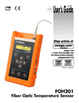
Download TempMonitor User Manual
Transcript
TempMonitor User Manual
TempMonitor
User Manual
© Opsens inc.
IMP0123-v1 TempMonitor Manual.doc
i
TempMonitor User Manual
© Opsens inc.
IMP0123-v1 TempMonitor Manual.doc
ii
TempMonitor User Manual
TempMonitor
User Manual
Opsens inc
2014 Cyrille-Duquet, Suite 125
Québec, QC
G1N 4N6, Canada
Tel. : +418-682-9996
Fax: +418-682-9939
[email protected]
www.opsens.com
© Opsens inc.
IMP0123-v1 TempMonitor Manual.doc
iii
TempMonitor User Manual
© Opsens inc.
IMP0123-v1 TempMonitor Manual.doc
iv
TempMonitor User Manual
WARRANTY
All signal conditioner manufactured by Opsens inc. are warranted to be free of defects in
workmanship and materials for a period of six years from the date of shipment. No other
express warranty is given, and no affirmation of Seller, by words or actions, shall constitute a
warranty. SELLER DISCLAIMS ANY IMPLIED WARRANTIES OF MERCHANTABILITY OR
FITNESS FOR ANY PARTICULAR PURPOSES WHATSOEVER. If any defect in workmanship
or material should develop under conditions of normal use and service within the warranty
period, repairs will be made at no charge to the original purchaser, upon delivery of the
product(s) to the factory, shipping charges prepaid. If inspection by Opsens or its authorized
representative reveals that the product was damaged by accident, alteration, misuse, abuse,
faulty installation or other causes beyond the control of Opsens, this warranty does not apply.
Service, repairs or disassembly of the product in any manner, performed without specific
factory permission, voids this warranty.
OPSENS MAKES NO WARRANTY OF ANY KIND WITH REGARD TO THIS MANUAL,
INCLUDING, BUT NOT LIMITED TO, THE IMPLIED WARRANTIES OF MERCHANTABILITY
AND FITNESS FOR A PARTICULAR PURPOSE. Opsens shall not be liable for errors
contained herein or for incidental or consequential damages in connection with the furnishing,
performance, or use of this material.
This warranty does not apply to the transducers sold for use with Opsens’ signal conditioners.
IMPORTANT NOTICE
The product specifications and other information contained in this manual are subject to change
without notice.
Opsens has made a concerted effort to provide complete and current information for the proper
use of the equipment. If there are questions regarding this manual or the proper use of the
equipment, contact Opsens inc at:
TEL
FAX
+ 418-682-9996
+ 418-682-9939
WEB SITE
E-MAIL
www.opsens.com
[email protected]
PACKAGING FOR SHIPMENT
If the product must be shipped to a different location or returned to Opsens for any reason
through a common carrier it must be properly packaged to minimize risks of damage.
SOFTWARE LICENSE AGREEMENT
This product contains intellectual property, i.e. software programs, that are licensed for use by
the end user/customer (hereinafter “end user”).
This is not a sale of such intellectual property.
The end user shall not copy, disassemble or reverse compile the software program.
The software programs are provided to the end user “as is” without warranty of any kind, either
express or implied, including, but not limited to, warranties of merchantability and fitness for a
particular purpose. The entire risk of the quality and performance of the software program is
with the end user.
WARNINGS
© Opsens inc.
IMP0123-v1 TempMonitor Manual.doc
v
TempMonitor User Manual
WARNING: NOT EXPLOSION PROOF!
Installation of this instrument in an area requiring devices rated as
intrinsically safe is not recommended.
WARNING: VOLTAGE SUPPLY!
Use only the wall plug-in power supply delivered with your instrument
and verify that the input voltage and frequency are compatible with the
power outlet.
© Opsens inc.
IMP0123-v1 TempMonitor Manual.doc
vi
TempMonitor User Manual
TableofContents
1. 1.1 1.2 1.3 2. 2.1 2.1.1 2.1.2 2.1.3 2.1.4 2.2 2.3 2.3.1 2.3.2 2.3.3 2.3.4 2.3.5 2.3.6 2.3.7 2.3.8 2.4 3. 3.1 3.2 3.2.1 3.2.2 3.2.3 3.3 3.3.1 3.3.2 3.3.3 3.3.4 4. 4.1 4.2 4.2.1 4.2.2 4.2.3 4.2.4 4.2.5 4.3 4.4 5. Quick start ........................................................................................................... 1 TempMonitor Powering...................................................................................................................................................... 1 Sensor Connection............................................................................................................................................................. 1 Sensor Reading .................................................................................................................................................................. 2 Local Operation................................................................................................... 3 Keyboard ............................................................................................................................................................................. 3 Menu Button ......................................................................................................................................................................... 3 Left/Right Arrows .................................................................................................................................................................. 3 Up/Down Arrows................................................................................................................................................................... 3 Confirmation Button .............................................................................................................................................................. 3 Main Menu ........................................................................................................................................................................... 3 Setting Submenu ................................................................................................................................................................ 4 Channels............................................................................................................................................................................... 4 Average ................................................................................................................................................................................ 4 Analog Scaling (Analog Scl) ................................................................................................................................................. 4 Units...................................................................................................................................................................................... 5 Communications ................................................................................................................................................................... 5 Bypass FAIL (BPass-FAIL)................................................................................................................................................... 5 Scrolling ................................................................................................................................................................................ 5 Description (Descript.) .......................................................................................................................................................... 6 Diagnostic Submenu .......................................................................................................................................................... 6 Relay option......................................................................................................... 8 General description ............................................................................................................................................................ 8 Theory of operation ............................................................................................................................................................ 9 Temperature monitoring relay mode .................................................................................................................................... 9 System Alarm relay mode................................................................................................................................................... 10 Failsafe relay mode ............................................................................................................................................................ 10 Configuring the relays from the front panel .................................................................................................................. 11 Select Relay Channels (Sel RLY CH) ................................................................................................................................ 11 Setpoints............................................................................................................................................................................. 11 System Alarm (Syst Alrm)................................................................................................................................................... 12 Failsafe ............................................................................................................................................................................... 12 Internal Memory ................................................................................................ 13 General description .......................................................................................................................................................... 13 Configuring the memory from the front panel ............................................................................................................... 13 Set Period ........................................................................................................................................................................... 14 Start .................................................................................................................................................................................... 14 Stop ACQ............................................................................................................................................................................ 14 Maximum Temperature (Max Temp) .................................................................................................................................. 15 Delete All ............................................................................................................................................................................ 15 During an acquisition ....................................................................................................................................................... 16 Acquisition file retrieval ................................................................................................................................................... 16 4-20mA or 0-1mA Analog Current option ....................................................... 17 5.1 5.2 5.3 5.3.1 5.3.2 5.3.3 General description .......................................................................................................................................................... 17 Wiring the 4-20mA or the 0-1mA loops .......................................................................................................................... 18 Temperature/Current scaling........................................................................................................................................... 19 Default scaling for the 4-20mA outputs .............................................................................................................................. 19 Default scaling for the 0-1mA outputs ................................................................................................................................ 19 Scaling modification............................................................................................................................................................ 19 6. Remote operation.............................................................................................. 21 © Opsens inc.
IMP0123-v1 TempMonitor Manual.doc
vii
TempMonitor User Manual
© Opsens inc.
IMP0123-v1 TempMonitor Manual.doc
viii
TempMonitor User Manual
1. Quick start
1.1
TempMonitor Powering
The TempMonitor accepts supply voltage form 12 to 30 VDC (except when the relay
option is installed, the voltage is then limited to a maximum of 24 VDC). The supply
connection is on the front panel and is ground on the left and positive on the right (Figure
1).
Connect the plug-in wall or tabletop power supply to a power outlet. Verify that the power
supply complies with the voltage and frequency outlet. Connect the power cable to the
TempMonitor power connector (Figure 1). Once connected, the green LED should go on
indicating that the TempMonitor is powered correctly. The red LED will go on if a
System Alarm is generated, following a FAIL condition of the system.
NOTE: Input voltage is limited to 12-24 VDC when the relay option is installed.
ON / OFF Switch
Status LED’s
RS-232 connector
RS-485 connector
Power-supply
connector
Figure 1 : Power Supply Connector
1.2 Sensor Connection
The TempMonitor is compatible with all Opsens’ GaAs-type of sensors or transducers
for measuring temperature namely the OTG series. The fiber-optic connector provided
with the OTG sensors is an ST-type connector. Remove the protective cap of the
TempMonitor ST mating and engage the sensor connector with the orientation key
properly oriented (Figure 2). It is mandatory to clean the sensor connector prior to
connection to the signal conditioner. Ask for Opsens Fiber-Optic Cleaning Guide for
further information on how to clean fiber-optic connectors.
© Opsens Inc.
IMP0123-v1 TempMonitor Manual.doc
1
TempMonitor User Manual
NOTE: Always replace the protective dust cap on the mating when there is no
sensor connected. Always replace the protective dust cap on the sensor
fiber-optic connector when not in used.
ST Mating
ST-type fiber-optic
sensor connector
Figure 2: Fiber-Optic Sensor Connection
1.3 Sensor Reading
Once the fiber-optic sensor is connected, the TempMonitor is ready to measure
temperature. The instrument display shows the temperature measurements (default unit
is °C) for up to 8 optical channels at one time (Figure 3), with automatic or manual
scrolling available. If the Description option is selected, the temperature value is
displayed along with the corresponding channel description (Figure 4). Again, automatic
or manual scrolling of all channels is available. The measurement readings are also
available at either the RS-232 or the RS-485 port.
Figure 3: Temperature Measurement Display
Figure 4: Temperature Measurement Display
with Optional Channel Description
© Opsens Inc.
IMP0123-v1 TempMonitor Manual.doc
2
TempMonitor User Manual
2. Local Operation
2.1 Keyboard
MENU
2.1.1
Menu Button
The Menu button gives access to the system menus. Once in the menu, this button
brings the user one level higher into the menu hierarchy. Once at the root, the
system will exit the menu and go back to measurement display.
MENU
2.1.2
Left/Right Arrows
The Left/Right arrows allow navigating 1) within a sub-menu, or 2) from one digit to
the other when a value is being entered.
2.1.3
Up/Down Arrows
The Up/Down arrows allow navigating 1) between menu items of a given hierarchical
level, or 2) in the menu to change a value being entered.
2.1.4
Confirmation Button
The Confirmation button permits confirming 1) a new value being entered, 2) confirm
the selection of a menu item then moving one hierarchical level lower, 3) refreshing
displayed value in the case of diagnostic.
2.2 Main Menu
When the Menu button is pressed, the display shows the following submenus:
•
Setting
•
Diagnostic
•
Relays (optional)
•
Memory
The Setting submenu is used to modify the general system settings such as channel
activation and remote communication configuration.
© Opsens Inc.
IMP0123-v1 TempMonitor Manual.doc
3
TempMonitor User Manual
The Diagnostic submenu is used to display indicators on the optical signal of each
channel. This is useful when troubleshooting.
A Relays submenu appears on instruments equipped with the optional relay module and
is used to configure the relay operation.
The Memory submenu is used to configure and manage internal acquisition files.
See next sections for more information on each of these submenu functions.
2.3 Setting Submenu
The functions below are used to setup specific parameters of the instrument. Some of
the settings are not necessarily related to a specific sensor.
2.3.1 Channels
Optical channels can be enabled (ON) or disabled (OFF) individually. All channels are
ON by default.
2.3.2 Average
The user can set ON or OFF the averaging mode (ON by default). When ON, the
measurements displayed on the front panel display, outputted on the analog output and
transmitted to the RS-232 port is the average of 5 sequential measurements.
This parameter is not saved and is lost when the system is switched off.
2.3.3 Analog Scaling (Analog Scl)
Two analog output options are available on the TempMonitor. We offer either a 4-20mA
current output or a 0-1mA current output.
4-20mA current output
Standard scaling parameters are set in factory; however the user can configure the
required scaling by selecting the minimum temperature value corresponding to 4mA and
the maximum temperature value corresponding to 20mA current output.
The resulting scale can be displayed on the front panel display.
See section 5 for more details on the 4-20mA output.
© Opsens Inc.
IMP0123-v1 TempMonitor Manual.doc
4
TempMonitor User Manual
0-1mA current output
Standard scaling parameters are set in factory; however the user can configure the
required scaling by selecting the minimum temperature value corresponding to 0mA and
the maximum temperature value corresponding to 1mA current output.
The resulting scale can be displayed on the front panel display.
See section 5 for more details on the 0-1mA output.
2.3.4 Units
The user can choose between Celsius and Fahrenheit degrees for the temperature
measurement display. This choice affects the values on the display, on the analog
output as well as the values sent by the serial port.
Note that when the units are changed, the analog output scale usually needs to be
adjusted.
2.3.5 Communications
In the Communications submenu, the user can choose between RS-232 and RS-485
port and also between the SCPI and Modbus communication protocols.
Baud Rate and Parity settings can also be set in the Communications submenu.
For Modbus communication, the user can also choose the ID number of the instrument.
The default Modbus ID number is 107 and the permitted values are from 1 to 247. The
ID number is saved in the non volatile memory of the TempMonitor
NOTE: When the Modbus ID is changed, the instrument has to be power-cycled
on/off for the change to be effective.
2.3.6 Bypass FAIL (BPass-FAIL)
The TempMonitor automatic diagnostic functionality can be disabled by setting the
BPass-FAIL to OFF. See section 2.4 for more detailed information.
This setting is not saved and is lost when the system is powered OFF and back ON.
2.3.7 Scrolling
The Scrolling option allows continuous automatic scrolling of temperature readings and
channel description for each optical channel on the front panel display of the
TempMonitor.
This feature is particularly interesting when the TempMonitor is equipped with 5 or more
optical channels as it allows the user to visually monitor all channels sequentially when
the feature is turned ON.
© Opsens Inc.
IMP0123-v1 TempMonitor Manual.doc
5
TempMonitor User Manual
If the user wishes to monitor a specific channel number and does not wish to scroll all
available channels, the feature can be turned OFF. The user can then manually select
the channel to monitor on the display using the up
and down
buttons.
2.3.8 Description (Descript.)
The Description option allows display of the descriptions attributed by the user for each
optical channel.
When the Description option in turned ON, the channel description will be displayed to
the right of the temperature value in the front panel display. By default, the Description
option is turned OFF.
Channel descriptions are created using Opsens’ PC application SoftSens. Refer to
SoftSens manual for channel description creation.
2.4 Diagnostic Submenu
The user can look through a variety of internal parameters for each measuring channel
of the TempMonitor. This can be useful to diagnostic potential problems with the system
or a specific sensor. Typical diagnostic parameters are shown below. Diagnostic values
can be refreshed by pressing the confirmation button . The channel number to
and down
buttons.
diagnostic can be changed with the up
Parameter and unit values
Description
Lm %
Lamp driving level
Lg Volts
Light level
Sg (no units)
Signal amplitude
The following table shows diagnostic values with good signal, poor signal, or with a
broken sensor (“fault”). A fault condition results in a “FAIL” being displayed.
Parameter
Good signal
Poor Signal
Fault
Lm
< 100 %
> 100 %
—
Lg
> 2.2
< 2.2
—
Sg
> 6 000
< 6 000
< 4 000
NOTE: Without a sensor connected, the instrument shows the message “FAIL”
on its front panel display.
In the unlikely situation that this message appears while a sensor is connected to the
unit, take note of the diagnostic parameters and contact Opsens technical support.
© Opsens Inc.
IMP0123-v1 TempMonitor Manual.doc
6
TempMonitor User Manual
During a FAIL condition, the analog output and the serial ports output constant values as
follow:
Output
Analog current (4-20mA
option)
Analog current (0-1mA option)
FAIL condition output value
0 mA
RS-232 or RS-485 SCPI
65 536.0
RS-232 or RS-485 ModBus
999.99
4 mA
There are certain circumstances (i.e. when using some remote control programs) where
it is not desirable to have these above constant outputted on serial ports or analog
output. Bypassing the FAIL functionality will prevent this situation, see section 2.3.6
Bypass FAIL (BPass-FAIL) for location of submenu.
© Opsens Inc.
IMP0123-v1 TempMonitor Manual.doc
7
TempMonitor User Manual
3. Relay option
3.1 General description
The TempMonitor can be equipped with an optional relay module. 6 relays are included
and can be configured individually to one or more channels at the user’s choosing to
control alarms, cooling fans, etc. This very flexible configuration scheme makes it easy
to adapt this functionality to almost any specific operation context.
The relay module includes a total of 6 C-Form SPDT relays, each able to carry and
switch 5 A of up to 250 VAC or up to 30 VDC. Each relay is connected to a three pole
screw-type terminal block. The relays are numbered from 1 to 6 starting from the top
position, as illustrated in Figure 5.
Figure 5: Relay option.
NOTE: Power-supply voltage of the instrument is limited to 12-24 VDC when the
relay option is installed.
© Opsens Inc.
IMP0123-v1 TempMonitor Manual.doc
8
TempMonitor User Manual
For each relay, the centre terminal (2) is the common input, the left terminal (1) is the
normally-closed output and the right terminal (3) is the normally-open output. Figure 6
shows the wiring diagram.
Figure 6: Wiring diagram for each relay.
When the relay is activated, the normally-closed contact becomes open and the
normally-open contact becomes closed.
Figure 7: Relay Status LEDs
On the main display panel, the corresponding blue Relay Status LED will be lit when the
relay circuit is activated (Figure 7).
3.2 Theory of operation
The six available relays can be individual configured to be activated by temperature
monitoring conditions and/or a system alarm condition encountered on a single optical
channel or on multiple optical channels.
3.2.1 Temperature monitoring relay mode
Under the temperature monitoring mode, each relay has a setpoint and a hysteresis
condition.
The setpoint condition determines the minimum temperature level at which the relay is
activated.
The hysteresis determines the number of degrees lower than the setpoint required to
deactivate the relay.
Hence, once a relay is activated, the temperature needs to reach a level equal or lower
than the difference between the setpoint value and the hysteresis value, for the relay to
© Opsens Inc.
IMP0123-v1 TempMonitor Manual.doc
9
TempMonitor User Manual
be deactivated. This feature is useful for controlling cooling fans where the user wants to
stop the fans only when the temperature reaches a lower level than the one needed to
start the fan.
The setpoint and the hysteresis conditions are determined for each relay. Each relay can
then be associated with one or more measurement channels (if no channel is assigned
to a relay, this relay effectively becomes disabled).
The setpoint conditions can be made with a AND or OR logic. If the setpoint condition
for a given relay is set to AND, it means that ALL channels associated with this relay
have to reach a temperature equal or higher than the setpoint for the relay to be
activated. Conversely, if the setpoint is set to OR, then the relay is activated when at
least ONE channel gets a temperature reading that is equal or higher than the setpoint.
The hysteresis condition is set to AND by default. ALL channels associated with this
relay will have to reach a temperature level equal or lower than the difference between
the setpoint value and the hysteresis value, for the relay to be deactivated.
3.2.2 System Alarm relay mode
It might be desirable to activate a relay, thus start a fan or generate a distant alarm, if an
optical channel of the TempMonitor signal conditioner no longer provides a temperature
reading. In the impossibility by the TempMonitor to provide a temperature reading, FAIL
will be displayed on the front panel display next to the channel number.
If a FAIL condition is met, the red Status LED light on the front panel will go on.
Such failures are caused by problems encountered either along the optical link from the
sensor tip all the way to the fibre optic cables and extensions connected to the
TempMonitor signal conditioner, or a signal conditioner internal failure related to a given
channel. An optical cable may have been disconnected or damaged or the sensor may
be defective.
The relays can be programmed, in addition to temperature conditions, to trigger if such
FAIL conditions occur.
The AND or OR logic can be applied to the System Alarm relay configuration. If the
system fail condition for a given relay is set to AND, it means that ALL channels
associated with this relay have to reach a FAIL condition for the relay to be activated.
Conversely, if the system fail condition is set to OR, then the relay is activated when at
least ONE of the associated channels reaches a FAIL condition.
3.2.3 Failsafe relay mode
It is possible to force each individual relay to be, by default, into an activated mode. This
feature allows the status of the relay to change back to a deactivated mode if the
TempMonitor signal conditioner looses electrical power or if it is subject to an internal
failure that would cause the relay operation to stop.
© Opsens Inc.
IMP0123-v1 TempMonitor Manual.doc
10
TempMonitor User Manual
3.3 Configuring the relays from the front panel
In the Relays submenu, there are four submenus:
•
Select Relay Channels (Sel RLY CH)
•
Setpoints
•
System Alarm (Syst Alrm)
y
Failsafe
3.3.1 Select Relay Channels (Sel RLY CH)
In the Select RLY CH submenu, use the Up
and Down
buttons to select the relay
number you want to configure and then press the Confirmation button
to edit the
parameters for this relay.
For a given relay number, the screen presents a list of all channels. Use the Up
Left
and
Right buttons to select the channel number you want to assign
Down
to the relay and then press the Confirmation button , the relay number will then be
displayed beside the selected channel. The characters “--“ beside a channel number
mean that this channel is not selected for this relay. If “Rx” (x being the relay number) is
written instead, it means that this channel is selected for this relay.
Press the Menu
MENU
button to go back to selecting the next relay number to configure.
Once done, press the Menu
MENU
button to move out of the setting submenus.
3.3.2 Setpoints
In the Setpoints submenu, the user can configure the setpoint, the hysteresis and the
logic for each relay. Use the Up
and Down
buttons to select the relay number and
to edit the parameters for this relay.
then press the Confirmation button
Down
Left
and
Right buttons to select
For a given relay number, use the Up
the parameter you wish to configure and then press the Confirmation button
to edit
Down
Left
and
Right buttons to edit the selected
this parameter. Use the Up
to lock down the new value
parameter value and then press the Confirmation button
entered.
Press the Menu
MENU
button to go back to selecting the next relay number to configure.
Note that the hysteresis mode is set to AND by default. It cannot be modified.
© Opsens Inc.
IMP0123-v1 TempMonitor Manual.doc
11
TempMonitor User Manual
In the Setpoints submenu, you can see for each relay which channels have been
assigned to each relay, but channel selection cannot be edited from the Setpoints
submenu. Channel selection can only be done in the Select RLY CH submenu.
Once done, press the Menu
MENU
button to move out of the setting submenus.
3.3.3 System Alarm (Syst Alrm)
In the Syst Alrm submenu, use the Up
and Down
buttons to select the relay
to edit the
number you want to configure and then press the Confirmation button
parameters for this relay.
For a given relay number, the screen presents a list of all channels. Use the Up
Left
and
Right buttons to select the channel number you want to assign
Down
to the relay and then press the Confirmation button , the relay number will then be
displayed beside the selected channel. The characters “--“ beside a channel number
mean that this channel is not selected for this relay. If “Rx” (x being the relay number) is
written instead, it means that this channel is selected for this relay.
Press the Menu
MENU
button to go back to selecting the next relay number to configure.
Press the Menu
MENU
button to move out of the setting submenus.
3.3.4 Failsafe
In the Failsafe submenu, use the Up
and Down
buttons to select the relay number
to edit the parameters
you want to configure and then press the Confirmation button
for this relay.
For a given relay number, the screen presents a YES or NO option list. Use the Up
buttons to select the desired configuration for the selected relay and then press
Down
to lock down the configuration entered.
the Confirmation button
To configure another relay in Failsafe mode, go back into the Failsafe submenu and use
and Down
buttons to select the next relay number you want to configure
the Up
to edit the parameters for this new relay.
and then press the Confirmation button
Repeat the YES or NO configuration for this relay and all the other relays you wish to
configure in Failsafe mode.
Once done, press the Menu
© Opsens Inc.
IMP0123-v1 TempMonitor Manual.doc
MENU
button to move out of the setting submenus.
12
TempMonitor User Manual
4. Internal Memory
4.1 General description
The TempMonitor signal conditioner is supplied with an onboard non-volatile Flash
memory chip. The Flash memory allows over 2 000 000 individual temperature
measurements to be stored.
A maximum of 8 acquisition files can be stored in the TempMonitor internal memory,
whether or not the 2 000 000 available measurement spaces have been used.
After all the available memory has been filled or if 8 acquisition files are stored in the
Flash Memory chip, the memory will have to be cleared, either by retrieving the files
using SoftSens or by deleting the files, to allow for new acquisition procedures.
4.2 Configuring the memory from the front panel
The measure period is the main parameter to configure. It corresponds to the frequency
at which you want the instrument to memorize one temperature measurement value for
each optical channel that is enabled.
The measure period is set in number of seconds, so for example, if 1 temperature
measurement per channel is required every 15 minutes, then the value entered should
be (15 minutes x 60 seconds/minute = 900 seconds) 900.
Note that the measure period cannot be set to a value lower than the instrument’s
minimal measure period, which is determined by the number of optical channels that are
enabled and the time to switch through all channels. If a lower value is entered, the
instrument’s minimal measure period will be activated.
Note that the measure period value entered by the user will be rounded up or down to
the closest compatible time value, corresponding to a factor of the instrument’s minimal
measure period.
Acquisitions can be manually started, stopped and deleted from the TempMonitor signal
conditioner. More advanced acquisition configuration is available through Opsens’
SoftSens application. Please refer to the SoftSens User Manual.
In the Memory submenu, there are four submenus:
y
Set Period
y
Start
y
Stop Acquisition (Stop ACQ)
y
Maximum Temperature (Max Temp)
y
Delete All
© Opsens Inc.
IMP0123-v1 TempMonitor Manual.doc
13
TempMonitor User Manual
4.2.1 Set Period
In the Set Period submenu, use the Left
and
Right buttons to select the digit you
and Down
buttons to edit the digit of the
want to edit and then use the Up
measure period value in number of seconds. When all digits are set, press the
to lock down the new value entered.
Confirmation button
The newly set measure period will be displayed in the Set Period submenu.
Note that the measure period value entered by the user will be rounded up or down to
the closest compatible time value, corresponding to a factor of the instrument’s minimal
measure period.
4.2.2 Start
In the Start submenu, the screen presents a YES or NO option list, use the Up
and
Down
buttons to select Yes or NO and then press the Confirmation button
to lock
down the new value selected.
The acquisition procedure will go on until either it is stopped manually through the Stop
submenu or until the remaining memory space is filled up.
If the available memory has been filled or if 8 acquisition files are stored in the Flash
Memory chip the TempMonitor will not allow a new acquisition to be started and the
following message will appear:
Measure(Meas) Acquisition(ACQ) is running. Press Menu to Exit
Existing acquisition files will need to be downloaded to a computer using Opsens’
SoftSens application (or SCPI commands) or deleted from the internal memory for a new
acquisition to be started.
4.2.3 Stop ACQ
In the Stop ACQ submenu, the screen presents a YES or NO option list, use the Up
and Down
buttons to select Yes or NO and then press the Confirmation button
to
lock down the new value selected.
© Opsens Inc.
IMP0123-v1 TempMonitor Manual.doc
14
TempMonitor User Manual
4.2.4 Maximum Temperature (Max Temp)
The Maximum Temperature submenu will display the maximum temperature measured,
along with its time stamp, for each optical channel during an internal memory acquisition
procedure (Figure 8).
Figure 8: Maximum memory temperature display
The maximum temperature value will be continuously updated during the acquisition
procedure. When the acquisition procedure is finished, the maximum temperature values
will be kept in memory for display on the TempMonitor front panel until the next
acquisition procedure is activated, after which the maximum temperature values
displayed will correspond to the live acquisition procedure.
The maximum measured temperature for each optical channel during an acquisition
procedure will be saved and provided in the acquisition file after download to your PC
using Opsens’ SoftSens application. Please refer to the SoftSens User Manual.
The time stamp corresponds to the number of seconds since Midnight, on January 1st
1900. To determine the corresponding date and time, incorporate the following formula
in two different Microsoft Excel spreadsheet cells:
=(10 digit time stamps value / 86400)+2)
Then format the first cell to indicate the Time.
And format the second cell to indicate the Date.
For example, a time stamp value of 3477382987, as in Figure 8, will correspond to
11:43:07 of 2010-03-12.
4.2.5 Delete All
The TempMonitor front panel menus allow for the deletion of all the data files stored in
the internal memory. It will not allow the deletion of an individual acquisition file. To
delete individual files use Opsens’ SoftSens application or SCPI commands.
Note that the files will be deleted, so the data will be lost.
In the Delete All submenu, the screen presents a YES or NO option list, use the Up
and Down
buttons to select Yes or NO and then press the Confirmation button
to
lock down the new value selected.
© Opsens Inc.
IMP0123-v1 TempMonitor Manual.doc
15
TempMonitor User Manual
4.3 During an acquisition
During an acquisition procedure, either generated from the TempMonitor front panel or
from a computer using Opsens’ SoftSens application, the menu options on TempMonitor
front panel display will be limited in access.
The DIAGNOSTICS menu will be accessible, so that the system’s performance
parameters can be monitored during an acquisition procedure.
The SETTING and RELAYS menus will not be accessible, so that measurement
configurations cannot be modified during an acquisition procedure. The following
message will appear:
Measure(Meas) Acquisition(ACQ) is running. Press Menu to Exit
The MEMORY menu will be accessible but only to Stop an ongoing acquisition
procedure that was generated from the TempMonitor instrument or from the SoftSens
application for an internal memory acquisition procedure.
If the ongoing acquisition procedure was generated using SoftSens for a live data
download to the computer, then the acquisition procedure will need to be stopped from
the computer using the SoftSens application.
4.4 Acquisition file retrieval
Acquisition file retrieval can either be done using Opsens’ SoftSens application or a
communication terminal using SCPI commands on a computer connected to the
TempMonitor using the straight DB9 cable supplied.
Please refer to the SoftSens User Manual or Opsens’ SCPI Serial Communication
Manual.
© Opsens Inc.
IMP0123-v1 TempMonitor Manual.doc
16
TempMonitor User Manual
5. 4-20mA or 0-1mA Analog Current option
5.1 General description
The TempMonitor can be equipped with optional 4-20mA output or 0-1mA output. There
is one active output per active channel. Figure 9 and Figure 10 show the front panels
where each channel has two dedicated screw-in terminals for wire sizes from 26 AWG to
16 AWG.
The temperature/current scaling is factory-set depending on the option selected.
Figure 9: 4-20mA optional panel.
© Opsens Inc.
IMP0123-v1 TempMonitor Manual.doc
17
TempMonitor User Manual
Figure 10: 0-1mA optional panel.
5.2 Wiring the 4-20mA or the 0-1mA loops
Each channel controls the current in the loop and supply its own power source (12 V).
Thus, the user does not have to provide a separate power supply. Figure 11 shows the
wiring diagram.
© Opsens Inc.
IMP0123-v1 TempMonitor Manual.doc
18
TempMonitor User Manual
Figure 11: Wiring diagram for 4-20mA or 0-1mA loops
5.3 Temperature/Current scaling
5.3.1 Default scaling for the 4-20mA outputs
All channels share the same original, factory-set, configuration: the scale factor is
20 °C/mA.
This setting results in the 0 °C offset to be at 5 mA, the minimum 4 mA scale limit to be
at -20 °C and the maximum 20 mA scale limit to be at 300 °C.
For example, if one loop reads 9.8 mA, thus the temperature for that channel is (9.8 mA
– 5.0 mA) × 20 °C/mA = 96 °C.
5.3.2 Default scaling for the 0-1mA outputs
All channels share the same original, factory-set, configuration: the scale factor is 333.33
°C/mA.
This setting results in the 0 °C offset to be at 0.180 mA, the minimum 0 mA scale limit to
be at -60 °C and the maximum 1 mA scale limit to be at 273.33 °C.
For example, if one loop reads 0.468 mA, thus the temperature for that channel is (0.468
mA – 0.180 mA) × 333.33 °C/mA = 96 °C.
5.3.3 Scaling modification
It is possible to modify the Temperature/Current scaling of both the 4-20 mA and the 0-1
mA outputs. This allows the user to personalize the Temperature/Current scaling
according to its specific application.
Temperature/Current scaling modification is done by modifying the temperature values
corresponding to the minimum and/or maximum current limits.
© Opsens Inc.
IMP0123-v1 TempMonitor Manual.doc
19
TempMonitor User Manual
The user will need to calculate the resulting Temperature/Current scaling corresponding
to the minimum and maximum temperature values entered. This scaling value will need
to be programmed in its SCADA/Data Acquisition System to provide exact temperature
readings.
In the Setting, Analog Scl submenu, use the Up
and Down
buttons to select either
the Temperature Minimum (Temp. MIN) or the Temperature Maximum (Temp. MAX)
setting menu, then press the Confirmation button
to edit the temperature value. Use
and
Right buttons to select the digit you want to edit and then use the
the Left
and Down
buttons to edit the digit to the desired level. When all digits are set
Up
press the Confirmation button
to lock down the new value entered.
Repeat this procedure for the other temperature level if required.
Once done, press the Menu
© Opsens Inc.
IMP0123-v1 TempMonitor Manual.doc
MENU
button to move out of the setting submenus.
20
TempMonitor User Manual
6. Remote operation
Opsens TempMonitor signal conditioner uses serial communication to allow control with
a remote computer. The TempMonitor can communicate using two different protocols:
either SCPI or Modbus, and two types of serial port: either RS-232 or RS-485.
The user can create its own remote control software using the various SCPI commands
or ModBus commands available for the TempMonitor. But for ease of operation, Opsens
provides its own control software, called SoftSens, which gives access to all the
functionalities of the TempMonitor conditioner, plus many more features and more
detailed configuration parameters. See SoftSens user manual for how to remotely
control the TempMonitor conditioner.
For those who want to develop their own remote control software, ask for Opsens SCPI
Serial communication user manual or ModBus Serial communication user manual to get
all the information about serial interfacing with the TempMonitor signal conditioner.
© Opsens Inc.
IMP0123-v1 TempMonitor Manual.doc
21


