1
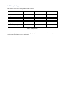
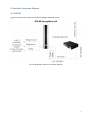
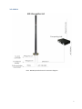
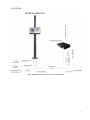
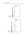
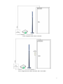
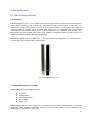
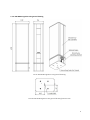
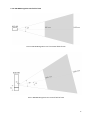
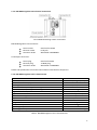
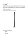
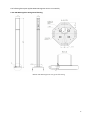
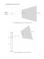
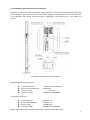
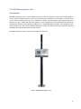
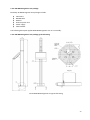
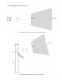
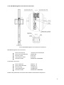
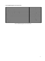
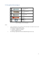
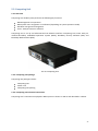
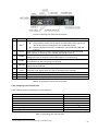
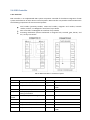
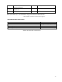
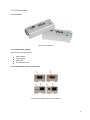
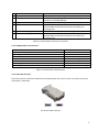
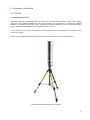
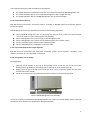
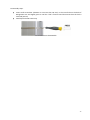
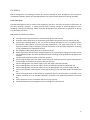
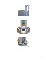
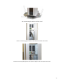
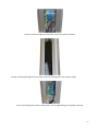
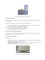
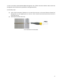
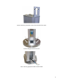
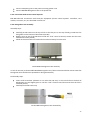
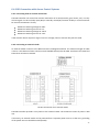
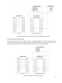
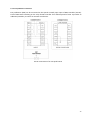
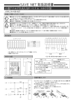
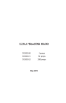
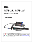
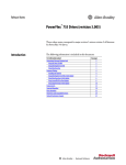
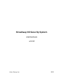
Broadway 3D Security System
USER MANUAL
v.1.1.0
Artec Group, Inc.
2012
Table of contents
1. General Information ........................................................................................ 3
2. Delivery Package ............................................................................................. 4
3.1. B3D BR ......................................................................................................... 5
3.2. B3D B ........................................................................................................... 6
3.3. B3D BM ........................................................................................................ 7
4. Integration with ACS ....................................................................................... 8
5. HW Specifications ......................................................................................... 10
5.1. B3D BR Recognition Unit ............................................................................ 10
5.2. B3D B Recognition Unit .............................................................................. 14
5.3. B3D BM Recognition Unit ........................................................................... 19
5.4. Recognition Unit mounting set ................................................................... 24
5.5. Computing Unit .......................................................................................... 25
5.6. B3D Controller ............................................................................................ 27
5.7. VGA Extenders ........................................................................................... 29
6. Mechanical Installation ................................................................................. 31
6.1. B3D BR ....................................................................................................... 31
6.2. B3D B ......................................................................................................... 34
6.3. B3D BM ...................................................................................................... 40
6.4. B3D Connection with Access Control Systems ............................................ 47
2
1. General Information
The Broadway 3D (B3D) security system is designed for building highly reliable biometric stand-alone
access control systems (ACS). B3D system reads biometric information about face shape, compares it
with those biometric templates registered in the database, and makes the decision to issue control
signals to actuators controlling access to premises (turnstiles, locks, gates, etc.), while simultaneously
displaying information on the status of work on a monitor and LED indicators.
B3D system can also complement existing access control systems that are based on other identification
technologies, in order to improve their reliability and functionality. In those cases, B3D system interacts
with elements of the access control system - access control card readers and/or controllers having a
Wiegand interface.
B3D system can operate in either identification or verification mode. The type of biometric template
remains unchanged. Therefore, during operation of the system, at any time the system can be switched
from one mode to the other. If several B3D systems work as an integrated solution, then some of them
may operate in the mode of verification, and some in the mode of identification.
3
2. Delivery Package
B3D systems come in the packages described in Table 1.
Component
3D Camera
B3D Pole
Recognition Unit mounting set
Docking station
Computing Unit
VGA Extender
Monitor
Packaging
ASP software package
User Manual
B3D version B
+
+
+
+
+
o
o
+
+
+
B3D version BM
+
+
+
+
+
+
+
+
+
+
B3D version BR
+
o
o
+
+
o
o
+
+
+
Table 1. B3D packages
B3D Poles vary between B3D versions. Packaging may vary between B3D Versions. The rest components
are the same for all B3D versions, if included.
4
3. Electrical Connection Diagram
3.1. B3D BR
Figure 1 illustrates basic electrical connection diagram of B3D BR system.
FIG 1. B3D BR basic electrical connection diagram
5
3.2. B3D B
FIG 2. B3D B optional electrical connection diagram
6
3.3. B3D BM
FIG 3. B3D BM optional electrical connection diagram
7
4. Integration with ACS
Figures 4 to 7 show typical scenarios of integration of B3D B/BM/BR with Access Control Systems.
FIG 4. Integration with an actuator
FIG 5. Integration with an actuator and a card reader
8
FIG 6. Integration with a door controller
FIG 7. Integration with a door controller and a card reader
9
5. HW Specifications
5.1. B3D BR Recognition Unit
5.1.1. Overview
B3D BR Recognition Unit is a part of B3D system that end users directly interact with. The Recognition
Unit is always installed at point of access (e.g. doors and turnstiles) with exception of cases when it is
used not for access control purposes but only as an enrollment station. The Recognition Unit captures
3D facial biometric of users, sends that data over Ethernet to the Computing Unit and provides
interaction with third parties Access Control Systems components via embedded B3D controller. The
Recognition Unit also provides users with visual feedback information about the B3D system and
recognition process conditions with the LED indication.
B3D BR Recognition Unit is an OEM unit. It may be mechanically integrated in and mounted on a
turnstile, wall, door, reception desk, tripod, and etc.
FIG 8. B3D BR Recognition Unit
5.1.2. B3D BR Recognition Unit package
B3D BR Recognition Unit package includes:
3D Camera
Docking station
Ethernet patch-cord
Power supply
Power cord
B3D BR Recognition Unit comes without any mounting set. Its mounting method depends on particular
integration and/or installation conditions. Mounting set for specific conditions may be designed and
delivered by the manufacturer upon order.
10
5.1.3. B3D BR Recognition Unit general drawing
FIG 9. B3D BR Recognition Unit general drawing
FIG 10. B3D BR Recognition Unit general drawing bottom view
11
5.1.4. B3D BR Recognition Unit field-of-view
FIG 11. B3D BR Recognition Unit’s horizontal field-of-view
FIG 12. B3D BR Recognition Unit vertical field-of-view
12
5.1.5. B3D BR Recognition Unit electrical connections
FIG 13. B3D BR Docking station connections
B3D BR Recognition Unit connectors:
Power socket
Ethernet socket
Connector #1 #2
Switchcraft L722RA
RJ-45 jack
Weidmuller 1045390000
Counterpart connectors:
Power plug
Ethernet plug
Connector #1 #2
Switchcraft S761K
TP-8P8C plug
Weidmuller 1748520000
Details and specifications of Connector #1 and #2 are described in Chapter 5.6.
5.1.6. B3D BR Recognition Unit’s characteristics
Parameter
Interface
Ethernet line distance, up to
Working distance
Linear field of view, HxW @ closest range
Linear field of view, HxW @ furthest range
Angular field of view, HxW
Light source
Video frame rate, up to
Exposure time
Dimensions, HxDxW
Weight
Power consumption
Operating temperature
Operating humidity
Value
Ethernet, Wiegand, Relay
90 meters
0,8 – 1,6 m
646x490 mm
1292x980 mm
44х340
Flash bulb (no laser)
15 fps
0,2 ms
470х129х94 mm
3,5 kg
100-240 VAC @ 60 W
15 – 30 0С
15% - 80% non-condensing
Table 2. B3D BR Recognition Unit’s characteristics
13
5.2. B3D B Recognition Unit
5.2.1. Overview
B3D B Recognition Unit is a part of B3D system that end users directly interact with. The Recognition
Unit is always installed at point of access (e.g. turnstiles) with exception of cases when it is used not for
access control purposes but only as an enrollment station. The Recognition Unit captures 3D facial
biometric of users, sends that data over Ethernet to the Computing Unit and provides interaction with
third parties Access Control Systems components via embedded B3D controller. The Recognition Unit
also provides users with visual feedback information about the B3D system and recognition process
conditions with the LED indication.
B3D B Recognition Unit is meant to be mounted on the floor.
FIG 14. B3D B Recognition Unit
5.2.2. B3D B Recognition Unit package
B3D B Recognition Unit package includes:
3D Camera
B3D B Pole
Ethernet patch-cord
Power supply
14
The following description applies B3D B Recognition Unit as an assembly.
5.2.3. B3D B Recognition Unit general drawing
FIG 15. B3D B Recognition Unit general drawing
15
5.2.4. B3D B Recognition Unit field-of-view
FIG 16. B3D BR Recognition Unit’s horizontal field-of-view
FIG 17. B3D B Recognition Unit vertical field-of-view
16
5.2.5. B3D B Recognition Unit electrical connections
B3D B has one 3D Camera and three power supply connectors. Connectors are located inside the lower
part of the B3D B Pole. The connectors are accessible through a window located on the lower back part
of the B3D Pole. Each power supply connector is dedicated to one electrical line - null, phase and
ground.
FIG 18. B3D B Recognition Unit connections
B3D B Recognition Unit connectors:
Power terminal 12V
Power terminal 100-220V
Ethernet socket
Connector #1 #2
Phoenix Contact FFKDS/H1
WAGO-264
RJ-45 jack
Weidmuller 1045390000
Counterpart connectors:
Power cable 12V
Power cable 100-220V
Ethernet plug
Connector #1 #2
AWG 22 - 16
AWG 28 - 12
TP-8P8C plug
Weidmuller 1748520000
Details and specifications of Connector #1 and #2 are described in Chapter 5.6.
17
5.2.6. B3D B Recognition Unit characteristics
Parameter
Interface
Ethernet line distance, up to
Working distance
Linear field of view, HxW @ closest range
Linear field of view, HxW @ furthest range
Angular field of view, HxW
Light source
Video frame rate, up to
Exposure time
Dimensions, HxDxW
Weight
Power consumption
Operating temperature
Operating humidity
Value
Ethernet, Wiegand, Relay
90 meters
0,8 – 1,6 m
646x490 mm
1292x980 mm
44х340
Flash bulb (no laser)
15 fps
0,2 ms
1657х230х230 mm
17 kg
100-240 VAC @ 60 W
15 – 30 0С
15% - 80% non-condensing
Table 3. B3D B Recognition Unit’s characteristics
18
5.3. B3D BM Recognition Unit
5.3.1. Overview
B3D BM Recognition Unit is a part of B3D system that end users directly interact with. The Recognition
Unit is always installed at point of access (e.g. turnstiles) with exception of cases when it is used not for
access control purposes but only as an enrollment station. The Recognition Unit captures 3D facial
biometric of users, sends that data over Ethernet to the Computing Unit and provides interaction with
third parties Access Control Systems components via embedded B3D controller. The Recognition Unit
also provides users with visual feedback information about the B3D system and recognition process
conditions with the LED indication and the monitor.
B3D BM Recognition Unit is meant to be mounted on the floor.
FIG 19. B3D BM Recognition Unit
19
5.3.2. B3D BM Recognition Unit package
Broadway 3D BM Recognition Unit package includes:
3D Camera
B3D BM Pole
Monitor
Ethernet patch-cord
Power supply
VGA Extender
The following description applies B3D BM Recognition Unit as an assembly.
5.3.3. B3D BM Recognition Unit package general drawing
FIG 20. B3D BM Recognition Unit general drawing
20
5.3.4. B3D BM Recognition Unit field-of-view
FIG 21. B3D BM Recognition Unit’s horizontal field-of-view
FIG 22. B3D BM Recognition Unit vertical field-of-view
21
5.3.5. B3D BM Recognition Unit electrical connections
FIG 23. B3D BM Recognition Unit electrical connections
B3D BM Recognition Unit connectors:
Power terminal 12V
Power terminal 100-220V
Ethernet socket
VGA Extender socket
Connector #1 #2
Phoenix Contact FFKDS/H1
WAGO-264
RJ-45 jack
RJ-45 jack
Weidmuller 1045390000
Counterpart connectors:
Power cable 12V
Power cable 100-220V
Ethernet plug
VGA Extender plug
Connector #1 #2
AWG 22 - 16
AWG 28 - 12
TP-8P8C plug
TP-8P8C plug
Weidmuller 1748520000
Details and specifications of Connector #1 and #2 are described in Chapter 5.6.
22
5.3.6. B3D BM Recognition Unit characteristics
Parameter
Interface
Ethernet line distance, up to
Working distance
Linear field of view, HxW @ closest range
Linear field of view, HxW @ furthest range
Angular field of view, HxW
Light source
Video frame rate, up to
Exposure time
Dimensions, HxDxW
Weight,
Power consumption
Operating temperature
Operating humidity
Value
Ethernet, Wiegand, Relay
90 meters
0,8 – 1,6 m
646x490 mm
1292x980 mm
44х340
Flash bulb (no laser)
15 fps
0,2 ms
1657х372х431 mm
19 kg
100-240 VAC @ 100 W
15 – 30 0С
15% - 80% non-condensing
Table 4. B3D BM Recognition Unit characteristics
23
5.4. Recognition Unit mounting set
1
2
3
4
5
Bolt
DIN 933 M8x30 mm.
Quantity: 4
Metal anchor
DRM d М8х10х30 mm.
Quantity: 4
Hex screw
ST8x38 DIN 7976
Quantity: 4
Plastic dowel anchor
8x40 mm
Quantity: 4
Washer
M8 DIN 9021
Quantity: 4
Table 5. Recognition Unit mounting set
Notes:
i.
ii.
Various combinations of the mounting accessories listed in the Table 5 may be used
depending on particular installation cases:
a. (1)+(2)+(5) – installation on stone/brick
b. (3)+(4)+(5) – installation on concrete
c. (3)+(5) – installation on wood
This mounting is applicable for B3D B and B3D BM Recognition Units only
24
5.5. Computing Unit
5.5.1 Overview
Computing Unit of B3D system performs the following key functions:
B3D Recognition Unit operation
B3D System users recognition or verification (depending on system operation mode)
Database storage and management
Users’ attempts statistics collection
Computing Unit is set up and administrated via Ethernet interface. Computing Unit comes with preinstalled Broadway Embedded Operation System (BEOS), Broadway Security Software (BSS) and
Broadway Web Interface (BWI).
FIG 24. Computing Unit
5.5.2. Computing Unit package
Computing unit package includes:
Computing Unit
Power cord
Computing Unit packing
5.5.3. Computing Unit electrical connections
Computing Unit’s connections employed in B3D system are shown on FIG 27 and described in Table 6.
25
FIG 25. Computing Unit electrical connections
#
Name
1
DVI-I1
2
DVI-D1
3
LAN#1
4
LAN#2
5
Speakers
6
7
Power
socket
Switch
Power Led
Hdd Led
Description
Analog DVI-I connector is used to connect Computing Unit to:
VGA extender via DVI-VGA converter and VGA cable, which comes as a
part of VGA extender package (in case of B3D BW system)
Optional third party monitor, if needed (in case of B3D B and B3D BR
systems)
Digital DVI-D connector is used to connect Computing Unit to Optional third
party monitor, if needed (in case of B3D B and B3D BR systems)
Connector is used to connect Computing Unit to:B3D BR, B3D B or B3D BM
Recognition Unit via Ethernet cable (cable length is up to 90 meters)
Connector is used to connect Computing Unit to an Ethernet network to set up
and administrate the Computing Unit through
Connectors may be used to connect third party speakers to provide users with
optional audio feedback
Connector is used to connect Computing Unit to a standard 100-240 V power line
via power cord, which comes as a part of Computing Unit package
Switch is used to switch Computing Unit on and off
Indicates CU’s power state
Indicates HDD activity
Table 6. Computing Unit electrical connections
5.5.4. Computing Unit characteristics
Table 7 below reflects Computing Unit’s characteristic.
Parameter
Interfaces
Embedded software platform
Dimensions, HxDxW
Weight
Power consumption
Operating temperature
Operating humidity
Value
Ethernet, DVI-I, DVI-D
Linux
300х205х72 mm
2 kg
115/230 VAC @ 180 W
15 – 30 0С
15% - 80% non-condensing
Table 7. Computing Unit characteristics
1
DVI-I and DVI-D can be used separately or simultaneously.
26
5.6. B3D Controller
5.6.1. Overview
B3D controller is an implemented B3D system component intended for hardware integration of B3D
system with elements of other Access Control Systems. B3D controller can provide communication with
the following components of Access Control Systems:
Card readers (proximity-readers, smart-card readers, magnetic card readers, barcode
readers, and etc.) via Wiegand in interface of up to 64 bit
Door controllers via Wiegand out interface of up to 64 bit
Actuating mechanism (electro-mechanical or magnetic lock, turnstile, gate, barrier, and
etc.) via dry out contact
FIG 26. B3D Controller’s connectors layout.
LEFT CONNECTOR
Pinout
Description
RIGHT CONNECTOR
Pinout
Description
N1
Relay 1 output (common)
D0in
D0 of the Card reader
NC1
Relay 1 Normal Closed
Green*
NO1
Relay 1 Normal Opened
Hold*
To “Green” contact of the Card reader
To “Hold” contact of the Card reader
Tamper
NC output, opens when 3D camera
is being unattached.
Switches relay when closing to GND
GND
Ground
GND
Ground
Reserved
D0out
D0 of the Door controller
N2*
Relay 2 output (common)
D1in
D1 of the Card reader
NC2*
Relay 2 Normal Closed
Red*
To “Red” contact of the Card reader
NO2*
Relay 2 Normal Opened
Buzzer*
To “Buzzer” contact of the Card reader
Exit
button
Auxiliary*
27
Tamper
Door
contact*
GND
NC output, opens when 3D camera
is being unattached.
Used to control weather the door is
closed or not
Ground
+12V
12V output for the Card reader
GND
Ground
D1out
D1 of the Door controller
Note: pins marked by “*” are reserved for using in next version of B3D controller
Table 8. B3D controller connectors description.
5.6.2. B3D Controller characteristics
Parameter
User Interface
Administration Interface
Operating temperature
Operating humidity
Value
Wiegand input/output, Relay
Ethernet
15 – 30 0С
15% - 80% non-condensing
Table 9. B3D Controller characteristics
28
5.7. VGA Extenders
5.7.1. Overview
FIG 27. VGA Extenders
5.7.2. VGA Extender package
VGA extender package includes:
VGA extender
Power supply
VGA cable
DVI-VGA converter
5.7.3. VGA Extender electrical connections
FIG 28. VGA Extender electrical connections
29
#
1
2
Name
VGA Input
VGA Output
3
4
Brightness Trim Pot Control
Receiver RJ-45 Input
5
6
5V DC Power Supply Input
Sender RJ-45 Input
Description
Connect the B3D Computing Unit to this input
Connect the VGA display to this output port using VGA
connector inside B3D BM pole
Adjusting this control will brighten or dim the output video.
Connect a CAT-5e cable (terminated according to the
TIA/EIA-568-B specification) between the sending and receiving units
Connect the included 5V DC power supply to this input.
Connect a CAT-5e cable (terminated according to the
TIA/EIA-568-B specification) between the sending and receiving units.
Table 10. VGA Extender’s electrical connections
5.7.4. VGA Extender characteristics
Parameter
Ethernet line distance, up to
Signalling rate
Dimensions, HxDxW
Weight
Power consumption
Operating temperature
Operating humidity
Value
100 m
480 Mbit/s
93x46x35
0.15 kg
5 VDC @ 5 W
15 – 30 0С
15% - 80% non-condensing
Table 11. VGA Extender characteristics
5.7.5. DVI-VGA converter
DVI-VGA converter should be installed in the Computing Unit DVI-I port in order to provide connection
of Extender’s VGA cable.
FIG 29. DVI-VGA converter
30
6. Mechanical Installation
6.1. B3D BR
6.1.1. Recognition Unit set up
B3D BR Recognition Unit package includes 3D Camera, Docking station, Ethernet cable, Power supply
and Power cord. B3D BR Recognition Unit comes without any mounting set. Its mounting method
depends on particular integration and/or installation conditions. Mounting set for specific conditions
may be designed and delivered by the manufacturer upon order.
In case of temporary or demo installations, B3D Recognition Unit can be installed on a tripod or a flat
surface (e.g. table).
Please note that Recognition Unit should not be powered on during any described procedure.
FIG 30. B3D BR Recognition Unit on a tripod
31
The tripod should comply with the following requirements:
The tripod should have standard 1/4-20 UNC screw thread for attaching B3D Recognition Unit
The tripod should be able to carry on B3D BR Recognition Unit’s weight of 3,5 kg
The tripod should be able to hold B3D Recognition Unit at 1133 mm height
6.1.2. Electrical Connections
B3D BR electrical connections should be perform according to B3D BR electrical connection diagram
shown on Figure 1.
B3D BR electrical connection should be performed in the following sequence:
Connect B3D BR Recognition Unit to Computing Unit using UTP cat.5 cable (or Ethernet patchcord that comes as a part of Recognition Unit package),
Connect Recognition Unit’s power supply to the Recognition Unit,
Connect Recognition Unit’s power cord to the Recognition Unit’s power supply,
Connect Computing Unit’s power cord to Computing Unit,
Connect Computing Unit to LAN with a UTP cat.5 cable.
6.1.3. Connection with Access Control Systems
B3D BR electrical connections with third part equipment (Access control System’s controllers, card readers, turnstiles, etc.) are described in article 6.4.
6.1.4. Recognition Unit assembly
Assembly steps:
Carefully put 3D Camera on the top of the Docking station so the five pins on the top of the
Docking station go inside the five fixing holes on the bottom of 3D Camera (FIG 31).
Slightly press on top of the 3D Camera until the “click” sound is heard (it means that the inner lock has been safely closed).
Check out that 3D Camera is fixed and cannot be moved up from the Docking station.
FIG 31. B3D BR Recognition Unit assembly.
In case of necessity to disassemble B3D BR Recognition Unit, follow instructions below. Please note that
Recognition Unit should not be powered on during disassembly.
32
Disassembly steps:
Insert small screwdriver (diameter is not more than 1,8 mm) in the round hole on the back of
Recognition Unit and slightly press it until the “click” sound is heard that means that the lock is unclosed (FIG 32).
Carefully lift the 3D Camera up.
FIG 32. 3D camera disassemble.
33
6.2. B3D B
B3D B Recognition Unit package includes 3D Camera and B3D B Pole. Recognition Unit should be
assembled as follows. Please note that Recognition Unit should not be powered on during assembly.
6.2.1. Pole set up
The B3D B Recognition Unit is meant to be installed on the floor. There are no special requirements of
the floor material, however, it should provide fixture strong enough to avoid Recognition Unit’s wobbling, rocking and collapsing. Please note that Recognition Unit should not be powered on during
any described procedure.
B3D B Pole’s installation procedure:
Lift and remove two plastic covers from the back of the Pole (FIG 33)
Unfasten metal round cover on the bottom of the Pole and take the cover up and off (FIG 34)
Provide the following cables at the very center of further Recognition Unit’s installation place: three power cables (phase, null and grounding, AWG 28-12), one signal cable (UTP cat. 5) and
necessary number of wires enough to provide connection to the third part equipment according
to the predefined user installation scheme.
Run prepared cables inside the Pole as shown on FIG 35.
Mount the Pole at the floor level with Recognition Unit mounting set taking into account article
5.4 guidelines (FIG 36). The Pole should be oriented according to the predefined user behavioral
scenario.
Put the metal round cover back on the Pole and fix it.
Connect signal cable (UTP cat.5 cable or Ethernet patch-cord that comes as a part of Recognition
Unit package) to the Ethernet socket of the Pole (FIG 37).
Connect Recognition Unit power supply to the 12V power terminals (FIG 38).
Connect Recognition Unit power supply cord to the 100-220V power terminals (FIG 39).
Connect Recognition Unit power supply cord to the Recognition Unit’s power supply (FIG 40).
Connect three power cables (phase, null and grounding) to the 100-220V power terminals (FIG
41).
Connect required wires of the third part equipment (Access control System’s controllers, card readers, turnstiles, etc.) to the B3D controller’s connectors (for detailed information see article
6.4)
Insert two plastic covers at the back side one by one (FIG 42).
Attach 3D Camera to the recognition Unit according to the article 6.2.4.
34
FIG 33. Removing two plastic covers from the back of the Pole.
FIG 34. Taking the metal cover off.
FIG 35. Running prepared cables inside the Pole
35
FIG 36. Mounting the Pole at the floor level.
FIG 37. Connecting signal cable to the Ethernet socket of the Pole.
FIG 38. Connecting Recognition Unit power supply to the 12V power terminals.
36
FIG 39. Connect Recognition Unit power cord to the power terminals.
FIG 40. Connecting Recognition Unit power cord to the Recognition Unit’s power supply.
FIG 41. Connecting three power cables (phase, null and grounding) to the power terminals.
37
FIG 42. Inserting plastic covers at the back side.
6.2.2. Electrical Connections
B3D B electrical connections should be performed according to B3D B electrical connection diagram
shown on Figure 2.
B3D B electrical connection should be performed in the following sequence:
Connect B3D B Recognition Unit to Computing Unit using UTP cat.5 cable (or Ethernet patchcord that comes as a part of Recognition Unit package).
Connect Computing Unit to LAN with a UTP cat.5 cable.
Connect Computing Unit to the power line using power cord.
Connect B3D B Recognition Unit to the power line.
6.2.3. Connection with Access Control Systems
B3D B electrical connections with third part equipment (Access control System’s controllers, card readers, turnstiles, etc.) are described in article 6.4.
6.2.4. Recognition Unit assembly
Assembly steps:
Carefully put 3D Camera on the top of Pole so the five pins on the top of Pole go inside the five
fixing holes on the bottom of 3D Camera (FIG 43).
Slightly press on top of the 3D Camera until the “click” sound is heard (it means that the inner
lock has been safely closed)
Check out that 3D Camera is fixed and cannot be moved up from the Pole.
FIG 43. B3D B Recognition Unit assembly
38
In case of necessity to disassemble B3D B Recognition Unit, follow instructions below. Please note that
Recognition Unit should not be powered on during disassembly.
Disassembly steps:
Insert small screwdriver (diameter is not more than 1,8 mm) in the round hole on the back of
Recognition Unit and slightly press it until the “click” sound is heard that means that the lock is unclosed (FIG 44).
Carefully lift the 3D Camera up.
FIG 44. 3D camera disassemble.
39
6.3. B3D BM
B3D BM Recognition Unit package includes 3D Camera, B3D BM Pole and monitor. Recognition Unit
should be assembled as follows. Please note that Recognition should not be powered on during
assembly.
6.3.1. Pole set up
The B3D BM Recognition Unit is meant to be installed on the floor. There are no special requirements of
the floor material, however, it should provide fixture strong enough to avoid Recognition Unit’s wobbling, rocking and collapsing. Please note that Recognition Unit should not be powered on during
any described procedure.
B3D BM Pole’s installation procedure:
Lift and remove two plastic covers from the back of the Pole (FIG 45)
Unfasten metal round cover on the bottom of the Pole and take the cover up and off (FIG 46)
Provide the following cables at the very center of further Recognition Unit’s installation place: three power cables (phase, null and grounding, AWG 28-12), one signal cable (UTP cat.5) and
necessary number of wires enough to provide connection to the third part equipment according
to the predefined user installation scheme.
Run prepared cables inside the Pole as shown on FIG 47.
Mount the Pole at the floor level with Recognition Unit mounting set taking into account article
5.4 guidelines (FIG 48). The Pole should be oriented according to the predefined user behavioral
scenario.
Put the metal round cover back on the Pole and fix it.
Connect signal cable (UTP cat.5 cable or Ethernet patch-cord that comes as a part of Recognition
Unit package) to Ethernet socket of the Pole (FIG 49)
Connect VGA cable inside the Pole to VGA Extender R.
Fix VGA Extender R using nylon cable ties and special ledges inside the Pole (FIG 50).
Connect UTP cat.5 cable from Computing Unit’s Side to VGA Extender R (FIG 51).
Connect Recognition Unit power supply to 12V power terminals (FIG 52)
Connect Recognition Unit power supply cord to Recognition Unit’s power supply (FIG 53)
Connect Recognition Unit power cord to 100-220V power terminals (FIG 54)
Connect three power cables (phase, null and grounding) to 100-220V power terminals (FIG 55).
Connect required wires of the third part equipment (Access control System’s controllers, card readers, turnstiles, etc.) to the B3D controller’s connectors (for detailed information see article
6.4)
Insert two plastic covers at the back side one by one (FIG 56).
Attach special metal plate from the B3D BM Recognition Unit set to the monitor bracket with
two screws (FIG 57)
Fix the monitor on the plate using four M4 screws from B3D BM Recognition Unit package (FIG
58)
Connect power cord and VGA cord to the monitor (FIG 59)
Attach 3D Camera to the recognition Unit according to the article 6.2.4.
40
FIG 45. Removing two plastic covers from the back of the Pole.
FIG 46. Taking the metal cover off.
FIG 47. Running prepared cables inside the Pole
41
FIG 48. Mounting the Pole at the floor level.
FIG 49. Connecting signal cable to the Ethernet socket of the Pole.
FIG 50. Fixing VGA Extender R using nylon cable ties and special ledges inside the Pole.
42
FIG 51. Connecting UTP cat.5 cable from Computing Unit’s Side to VGA Extender R
FIG 52. Connecting Recognition Unit power supply to the 12V power terminals.
FIG 53. Connect Recognition Unit power cord to the power terminals.
43
FIG 54. Connecting Recognition Unit power cord to the Recognition Unit’s power supply.
FIG 55. Connecting three power cables (phase, null and grounding) to the power terminals.
FIG 56. Inserting plastic covers at the back side.
44
FIG 57. Attaching special metal to the monitor bracket with two screws
FIG 58. Fixing the monitor on the plate using four M4 screws.
FIG 59. Connecting power cord and VGA cord to the monitor
6.3.2. Electrical Connections
B3D BM electrical connections should be performed according to B3D BM electrical connection diagram
shown on Figure 3.
B3D BM electrical connection should be performed in the following sequence:
Connect B3D BM Recognition Unit to Computing Unit using UTP cat.5 cable (or Ethernet patchcord that comes as a part of Recognition Unit package).
Connect Computing Unit to LAN with a UTP cat.5 cable.
45
Connect Computing Unit to the power line using power cord.
Connect B3D BM Recognition Unit to the power line.
6.3.3. Connection with Access Control Systems
B3D BM electrical connections with third part equipment (Access control System’s controllers, card readers, turnstiles, etc.) are described in article 6.4.
6.3.4. Recognition Unit assembly
Assembly steps:
Carefully put 3D Camera on the top of Pole so the five pins on the top of Pole go inside the five
fixing holes on the bottom of 3D Camera (FIG 60).
Slightly press on top of the 3D Camera until the “click” sound is heard (it means that the inner lock has been safely closed)
Check out that 3D Camera is fixed and cannot be moved up from the Pole.
FIG 60. B3D B Recognition Unit assembly
In case of necessity to disassemble B3D BM Recognition Unit, follow instructions below. Please note that
Recognition Unit should not be powered on during disassembly.
Disassembly steps:
Insert small screwdriver (diameter is not more than 1,8 mm) in the round hole on the back of
Recognition Unit and slightly press it until the “click” sound is heard that means that the lock is unclosed (FIG 61).
Carefully lift the 3D Camera up.
FIG 61. B3D B Recognition Unit disassembly
46
6.4. B3D Connection with Access Control Systems
6.4.1. Connecting with an actuator mechanism
The B3D controller can control the actuator mechanism of an ACS (turnstile, gate, barrier, etc.) via a dry
contact signal. For this normally open (NO) or normally closed (NC) contacts of Relay 1 of the Connector
#1 are used. Parameters of relay:
Maximum switching voltage DC: 48 V
Maximum switching current DC: 7 А
Maximum switching voltage AC: 250 V
Maximum switching current AC: 10 А
If the actuator device requires a larger current or voltage, then an external relay must be used.
6.4.2. Connecting an external reader
An external reader connects to the B3D controller via Wiegand Interface. The maximum length of cable
is 150 m. The cable used must contain several shielded twisted pairs 24 AWG. Conductors for Data0 and
Data1 lines must be not twisted.
FIG 62. Connection of an external reader
The B3D Controller provides +12 V power to the external reader. The maximum current of power is 300
mA.
If necessary, an external reader can be powered from a separate power source. In that case, grounding
of the power sources should be united (FIG 63).
47
FIG 63. Connection of an external reader with a separate power supply
6.4.3. Connection of an ACS Controller
An ACS controller connects to the B3D controller via Wiegand Interface. The cable used must contain
several shielded twisted pairs 24 AWG. Conductors for Data0 and Data1 lines must be not twisted. The
grounding of the power sources for the B3D and ACS controllers must be united (FIG 64).
FIG 64. Connection of an ACS Controller
48
6.4.4. Exit pushbutton connection
Exit pushbutton (EPB) can be connected to the special normally open input of B3D controller (FIG 65).
Push of EPB causes switching on the relay of B3D controller for a definite period of time. It provides an
additional possibility to control an actuator mechanism.
FIG 65. Connection of an exit push button
49