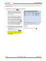
1
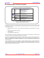
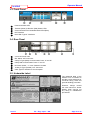
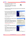
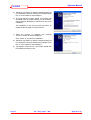
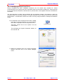
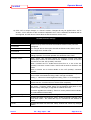
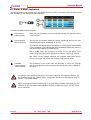
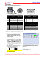
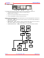
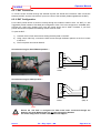
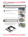
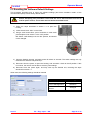
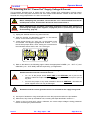
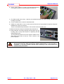
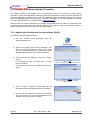
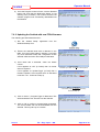
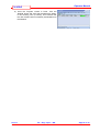
Operator Manual
SeaHub
4.6.3. Connecting other Serial Devices
The four serial ports on the SeaHub may be used as standard windows “COM” ports, and have any serial
device connected.
When used in RS232 mode, Ports “A” and “B” are wired with a standard 9-Way “DTE” pin out (Data
Terminal Equipment). This means that standard serial-extension leads or null-modem leads can be used
to connect to third-party DCE or DTE wired devices.
All ports support 3-wire RS232 (RX, TX and GROUND signals), however, the RTS and CTS signals are
also supported on Port “A”. Other ports should have “hardware flow control” settings disabled in the
relevant communication software being used.
When used in RS485 mode, the RX and TX lines become the “Data A” and “Data B” lines respectively of
the half-duplex differential pair (also sometime referred to as “DATA-” and “DATA+” respectively).
All ports support the Half-Duplex RS485 differential standard, however Port “B” also supports Full-Duplex
RS422. When configured in this mode, the “Data A” and “Data B” signal described above take on a
dedicated Transmit-Only function. Additionally pin-8 and pin-7 become “Data A” and “Data B” for a
dedicated Receive-Only function. When configured in RS422 mode, this port will still appear, and can be
used as, a standard windows COM port.
Power for peripherals using Port “A” or “B” can be derived from the three 4mm Power Output sockets on
the rear of the SeaHub. The voltage may be selected from one of three types of power supply. However,
if changing from the default “PWR” supply, ensure that the correct ground is also used, and necessary
signal grounds are provided otherwise the isolation barriers will prevent correct operation. Refer to
section 5.3 for details on the power supplies.
Ports C and D both use the Tritech standard 6-pin DIN pin out, and can operate in RS232 or RS485
mode, these ports will also supply the “PWR” power supply only, again refer to section 5.3 for details on
the power supplies.
Further details for creating application specific custom wiring looms to connect to any of the ports (for all
communication modes) can be found in section 6.
Connecting a Serial device to Port A to D…
1)
Recall the 6 x USB Serial Ports that were
allocated in Device Manager after the
SeaHub was connected and its drivers
installed. Refer to sections 4.2.2 & 4.2.3 on
page 17 onwards.
2)
In “Seanet Setup”, click on ‘Utilities’ | ‘Com
Setup’ to open the Channel Setup page
(see right). Ensure that the SeaHub “Aif”
interface is enabled and allocated to the
correct Com Port number (referring back to
the 6 x USB Serial Ports allocated).
3)
To connect a GPS device, enable the “GPS”
device and set it’s COM Port to match the
Port allocation in Device Manager;
Port A:
Port B:
Port C:
Port D:
COM Port = Base + 0.
COM Port = Base + 1.
COM Port = Base + 2.
COM Port = Base + 3.
In the Channel Setup table, refer to the
‘Type’ column for SeaHub Port description,
i.e. “SeaHubA” = Port A.
Issue 1
i.e. In previous example (see Section 4.2.2), the
SeaHub was installed with 6 x Serial Ports from
COM 9 to 14.
Therefore;
For GPS Input on Port A, Base + 0 = 9.
For SeaHub connection, Base + 4 = 13.
TIL – Eng – Spec – 080
Page 32 of 70