1
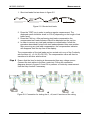
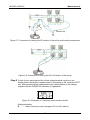
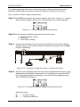
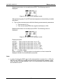
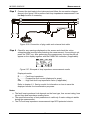
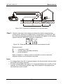
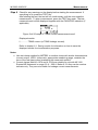
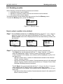
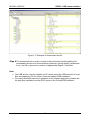
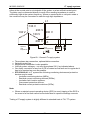
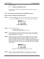
MI 3002 & MI3102 Measurements E H Rc S Rp >5d MPEC RE d Figure 5.40: Connection of standard 20 m long test leads Step 4 Check for warnings on the display and check the online voltage/terminal monitor before starting the measurement. If everything is ok, press the TEST key. After performing the measurement, the results will appear on the display together with the PASS/FAIL indication (if applicable). Figure 5.41: Example of resistance to earth measurement results Displayed results: R .............resistance to earth, RC ...........auxiliary earth electrode resistance, RP ...........probe resistance. Refer to chapter 6.1. Saving results for information on how to save the displayed results for documentation purposes. Notes: If a voltage higher than 30 V is present between the test terminals, the test will be prevented from being performed. If a noise voltage higher than approx. 5 V is present between the H and E or S test terminals, the (noise) warning symbol “ ” will be displayed, indicating that the test result may not be correct! 51