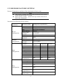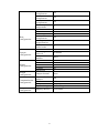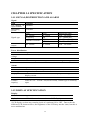
1
Heat Totalizer Meter User Manual FX1000 IML1-EZ01 First Edition FOREWORD Thank you for purchasing our flow meter! This manual is about the functions, settings, wiring methods, methods of operation, failure of treatment methods of the flow meter. To ensure correct use, please read this manual carefully and use properly before operation and keep this manual in a safe place for quick reference. Notice The contents of this manual are subject to change without prior notice as a result of continuing upgrades to the instrument’s performance and functions. Every effort has been made in the preparation of this manual to ensure the accuracy of its contents. However, if you have any questions or find any errors, please feel free to contact us. Copying or reproducing all or any part of the contents of this manual without our permission is strictly prohibited. Revisions Nov,2014, first edition I CHECKING THE CONTENTS OF THE PACKAGE Unpack the wrapping box and check the contents before operating the instrument. If some of the contents are not correct or missing or if there is any physical damage, contact our company or the sales network from which you purchased it. Instrument appearance Accessories Number Name Mounting bracket Quantity Notes For panel mounting 1 Mounting bracket 2 2 User’s Maual 1 WARNING This instrument has many plastic parts, so use dry soft cloth in cleaning. Do not use benzene agents, banana water and other pharmaceutical agents in cleaning, which may cause discoloration or deformation. Do not put the charged products near the signal terminals, which may cause malfunction. Please do not have big impact on the instrument. If you confirm that the instrument has smoke, odor, noise, etc, please immediately cut off the power supply and promptly get in touch with the suppliers or company. II FOREWORD ...................................................................................................................I CHECKING THE CONTENTS OF THE PACKAGE .................................................. II CHAPTER 1 OVERVIEW OF THE INSTRUMENT .................................................... 1 1.1 INTRODUCTION TO THE INSTRUMENT ........................................................ 1 1.2 INSTRUMENT STRUCTURE .............................................................................. 3 1.3 INSTRUMENT INSTALLATION ........................................................................ 4 1.4 INSTRUMENT WIRING ...................................................................................... 6 1.5 INSTRUMENT DISPLAY AND OPERATION .................................................... 8 1.5.1 DIGITAL DISPLAY SCREEN OPERATION ................................................ 9 1.5.2 SCREEN OPERATION OF INTERMEDIATE PARAMETERS ................. 10 1.5.3 SCREEN OPERATION OF HISTORY TREND .......................................... 10 1.5.4 FUNCTION SCREEN OPERATION ........................................................... 11 1.5.5 CONFIGURATION SCREEN OPERATION .............................................. 11 1.5.6 EDITING OPERATION OF CONFIGURATION PARAMETER ............... 13 CHAPTER 2 ANALOG SIGNAL INPUT .................................................................... 14 2.1 SIGNAL TYPE AND SPECIFICATION ............................................................. 14 2.2 SIGNAL DEBUGGING SCREEN ...................................................................... 14 2.3 INPUT CONFIGURATION ................................................................................ 15 2.3.1 SET THE BASIC PARAMETERS OF SIGNAL INPUT ............................. 16 2.3.2 SET SMALL SIGNAL CUTTING(REMOVAL ) ......................................... 18 2.3.3 SET FILTER PARAMETER(FILTER ) ........................................................ 18 2.3.4 SET LINEAR ADJUSTMENT (ADJUST K、B) ........................................ 18 2.3.5 SET DISCONNECTION COMPENSATION PARAMETER ...................... 18 2.3.6 MEASURING FREQUENCY CYCLE ........................................................ 18 CHAPTER 3 TEMPERATURE AND PRESSURE COMPENSATION ...................... 19 3.1 FLOW EXPRESSION OF COMMON FLOW SENSOR .................................... 20 3.2 PARAMETER CALULATION OF COMMON MATERIAL ............................. 22 3.3 CONVERSION OF VOLUME FLOW AND MASS FLOW ............................... 23 3.4 REYNOLDS NUMBER CALCULATION.......................................................... 23 3.5 DEVICE CONFIGURATION ............................................................................. 24 3.5.1 SELECT THE MEASURING DEVICE ....................................................... 25 3.5.2 SET PARAMETER OF STANDARD ORIFICE /NOZZLE / VENTURI TUBE ..................................................................................................................... 26 3.5.3 SET V-CONE FLOWMETER PARAMETER ............................................. 27 3.5.4 SET PARAMETER OF COMMON DIFFERENTIAL PRESSURE FLOWMETER ....................................................................................................... 28 3.5.5 PULSE OUTPUT(FREQUENCY VORTEX) FLOWMETER ..................... 29 3.5.6 SET PARAMETER OF CURRENT OUTPUT FLOWMETER ................... 30 3.5.7 ELBOW FLOWMETER ............................................................................... 30 3.5.8 MASS FLOWMETER .................................................................................. 30 3.6 MEDIUM CONFIGURATION ............................................................................ 31 3.6.1 SELECT THE MEASURING MEDIUM ..................................................... 31 3.6.2 SATURATED STEAM MEDIUM CONFIGURATION ............................. 32 3.6.3 SUPERHEATED STEAM MEDIUM CONFIGURATION ........................ 32 3.6.4 WATER MEDIUM CONFIGURATION....................................................... 33 3.6.5 GENERAL LIQUID MEDIUM CONFIGURATION .................................. 33 3.6.6 SINGLE GAS AND GENERAL GAS MEDIUM CONFIGURATION ....... 34 3.6.7 MIXED GAS AND ARTIFICIAL GAS MEDIUM CONFIGURATION ..... 35 3.7 FLOW CONFIGURATION ................................................................................. 36 3.7.1 SET BASIC FLOW PARAMETERS ........................................................... 36 3.7.2 SET ADVANCED SETTLEMENT PARAMETER .................................... 37 III 3.7.3 SET STEAM STOP JUDGING PARAMETER............................................ 38 3.7.4 CLEAR FLOW TOTAL AMOUT ................................................................ 38 CHAPTER 4 HEAT FUNCTION ................................................................................. 39 4.1 INTRODUCTION TO HEAT FUNCTION ......................................................... 39 4.2 HEAT CONFIGURATION .................................................................................. 39 4.3 CLEAR HEAT TOTAL AMOUNT ...................................................................... 40 CHAPTER 5 RS485 COMMUNICATION .................................................................. 41 5.1 REGISTER ADDRESS LIST .............................................................................. 41 5.2 CONNECTION MODE ....................................................................................... 42 5.3 COMMUNICATION CONFIGURATION .......................................................... 43 CHAPTER 6 ANALOG TRANSMITTER OUTPUT .................................................. 44 6.1 TRANSMITTER OUTPUT SPECIFICATION ................................................... 44 6.2 OUTPUT CONFIGURATION ............................................................................. 44 CHAPTER 7 CHANNEL ALARM .............................................................................. 45 7.1 ALARM AND CONFIGURATION ..................................................................... 45 7.2 ALARM LIST SCREEN ...................................................................................... 46 7.3 CLEAR ALARM LIST ........................................................................................ 46 CHAPTER 8 HISTORY DATA .................................................................................... 47 8.1 RECORDING FUNCTION AND CONFIGURATION ....................................... 47 8.2 HISTORY DATA QUERY SCREEN ................................................................... 48 8.3 CLEAR HISTORY RECORD .............................................................................. 48 CHAPTER 9 ACCUMULATIVE REPORT ................................................................. 49 9.1 ACCUMULATIVE REPORT FUNCTION AND CONFIGURATION ............... 49 9.2 ACCUMULATIVE REPORT QUERY SCREEN ................................................ 50 9.2.1 YEARLY REPORT SCREEN ....................................................................... 50 9.2.2 MONTHLY REPORT SCREEN ................................................................... 51 9.2.3 SHIFT REPORT SCREEN ........................................................................... 51 9.3 CLEAR ACCUMULATIVE REPORT ................................................................ 51 CHAPTER 10 POWER-DOWN RECORD .................................................................. 52 10.1 POWER-DOWN RECORD FUNCTION .......................................................... 52 10.2 POWER-DOWN RECORD QUERY SCREEN ................................................ 52 10.3 CLEAR POWER-DOWN RECORD ................................................................. 52 CHAPTER 11 SYSTEM LOG ...................................................................................... 53 11.1 SYSTEM LOG FUNCTION .............................................................................. 53 11.2 SYSTEM LOG QUERY SCREEN..................................................................... 53 CHAPTER 12 DOUBLE PASSWORD PROTECTION .............................................. 54 12.1 DOUBLE PASSWORD PROTECTION FUNCTION ...................................... 54 12.2 PASSWORD SETTING SCREEN..................................................................... 54 CHAPTER 13 SYSTEM CONFIGURATION ............................................................. 55 13.1 DATE AND TIME.............................................................................................. 55 13.2 INSTRUMENT NUMBER ................................................................................ 55 13.3 RESTORE FACTORY SETTING ...................................................................... 56 CHAPTER 14 SPECIFICATION.................................................................................. 58 14.1 SIGNAL,DISTRIBUTION AND ALARM........................................................ 58 14.2 DISPLAY SPECIFICATION ............................................................................. 58 14.3 GENERAL SPECIFICATION ........................................................................... 59 APPENDIX 1 COMMON GAS DENSITY IN STANDARD CONDITION ............... 61 APPENDIX 2 EXAMPLES OF STANDARD ORIFICE CONFIGURATION ........... 62 APPENDIX 3 EXAMPLE OF FREQUENCY VORTEX CONFIGURATION ........... 64 IV CHAPTER 1 OVERVIEW OF THE INSTRUMENT 1.1 INTRODUCTION TO THE INSTRUMENT In accordance with the relevant international standards, national and industry standards, this instrument has established a variety of flow mathematical models for different flow sensors and media in order to have accurate flow measurement and calculation. It can be widely used in the trade settlement and calcualting management network of petrochemical, chemical, metallurgy, electric power, light industry, medicine, city gas, heating and other industries. Scope of usage Suitable medium: gas, superheated steam, saturated steam, general gas, mixed gas, water, hot water, liquid (oil, chemical products), etc. Flow sensors: throttle flowmeters (all types of orifice plates, ISA1932 nozzle, long-diameter nozzle, venturi nozzle, and classic venturi tube), V-cone flowmeter, elbow flowmeter, vortex flowmeter, turbine flowmeter, electromagnetic flowmetes, mass flowmeters, etc. Compensation calcualtion Conduct real-time calculation on the discharge coefficient C, compression factor Z, and expansion rate of flow rate ε in throttle flowmeter according to GB/T2624-2006(ISO 5167-2003). The calculation of vapor density is based on IAPWS-IF97 formula. Calculating Management Automatic conversion of flow units, and setting of the segmented flow coefficient. Debugging calculus function: support to view the original value of analog signal; support to view various intermediate parameters in flow calculation, such as density ρ, the Reynolds number Red , discharge coefficient C compression factor Z, expansion coefficient ε, dynamic viscosity μ, isentropic index κ and other data. Trade settlement: small signal cut, blackout complement, small flow complement, overrun compensation measurement and other useful features. Audit record: blackout recording and logging operation function. Historical data: record the amount of flow, temperature, pressure, differential pressure (frequency) and the total instantaneous amount. Alarm list: record differential pressure (frequency), temperature, pressure and other instantaneous alarm information. 1 Accumulative report: support the accumulative flow, heating monthly report and annual report. Fault tolerance function: if there is any temperature, pressure signal abnormalities, use emergency parameter value to conduct compensate operation. Communication function: standard Modbus RTU protocol, RS-485 communication interface. 2 1.2 INSTRUMENT STRUCTURE Cover buckle 1 2 5 3 4 6 Cover buckle 7 1. LCD digital screen: display digital display screen, intermediate parameters, and historical curve. 2. Keyboard: left, right, increase, reduce, enter, page. 3. Operation cover: protect the keyboard by using the cover buckle to open operation cover. 4. Power terminal: Connect the power line and grounding protection line. 5. Terminal wiring diagram: signal wiring. 6. Signal terminals: connect the input and output signals. 7. Mounting bracket: fix instrument in panel mounting. 3 1.3 INSTRUMENT INSTALLATION Describe the installation site and instrallation method. Be sure to read this section before installation Notes: The instrument is panel mounting type. Please install it indoors to keep away from rain and direct sunlight In order to prevent the increase in the internal temperature of the instrument, please install it in a well-ventilated place. Do not tilt while installing the instrument, and try to have level installation (backward <30 °). Avoid the following places in installation: Near the place where there is direct sunlight and heat appliances. The working place in which temperature exceeds 50℃ The working place in which environment humidity exceeds 85%. Places near the occurance of electromagnetic source Mechanical vibration strong places. Place where temperature changes quckily and it is easy to dew. Places where there are much fume, steam, moisture, dust and corrosive gas. Installation method Please use 2 ~ 12 mm steel plates for the instrument panel. 1. Put the instrument in the front of the panel. 2. Use the mounting brackets of instrument to install as shown below: Use mounting brackets to fix on the both sides of the instrument The screws used in mounting bracket of panel are M4 standard screws. Installation diagram Instrument panel Mounting screw Front panel Screwdriver(cross) Mounting bracket 4 External dimensions unit: mm 68 76 80 150 160 61 Instrument installation dimensions Unit: mm Cartridge table hole size 76 +20 Min88 Single-table hole size 152 +20 Min164 5 1.4 INSTRUMENT WIRING Wiring method 1. Before wiring, please disconnect the power to the instrument. 2. the input / output signal line and the input / output terminal is connected. 3. In order to prevent poor contact, carefully tighten the screws after the wiring. 4. It is recommended to use the pressure line terminals with insulation sleeve (4mm screws are used). The pressure line terminals with insulation sleeve Please observe the following warning in the power wiring, or it may cause electric shock or damage to the instrument. NOTE To prevent electric shock, make sure that the instrument is not powered. To prevent fire, please use double insulated wire. Use terminals with insulated sleeve for power wiring and protective ground (4mm screws are used). Set air switch in the 220VAC/24VDC power circuit, and set the instrument seprated from the total power. Air switch specifications: current rating :> 3A Please connecte 2A ~ 15A fuse in the 220VAC power supply circuit. Please connect the 1A fuse in the 24VDC power supply circuit. Power specification Item Input voltage Input frequency Content 85VAC ~ 265VAC orDC~26VDC 50Hz Please note to prevent interference from entering the measurement circuit Please separate measuring circuit from power circuit or ground circuit. It would be better for the measurement object not to be the interfering source. Once it can not be avoided, please set insulation between measurement object and measuring circuit, and ground the measuring sensor. For the electrostatic induction interference, it is advisable to use shielded wires. For the interference produced by electromagnetic induction, it is better to intensively connect the measurement circuit wiring at the equal distance. If the input wiring is in parallel connection with other instrumentation, it will affect the measured values. 6 NOTE The input signal should not exceed the following value; otherwise it will damage the instrument. Current : -4mA ~ +25mA The largest common mode interference voltage: 250VACrms(50Hz) Terminals and wiring diagram 7 1.5 INSTRUMENT DISPLAY AND OPERATION Screen display The instrument is equipped with a monochrome dot-matrix liquid crystal display device. Use [page] key to have circular switching of the screen, use [left] + [page] key to enter the configuration. 2012-06-01 09:05:09 Data 11-11-15 15:50:00 Diffp 37.000 kPa Density 7.7265 kg/m3 t/h H Flow 10.00 230.0 ℃ H 2.000 MPa L 003456789 Function Signal Hisdata Alarmlist Password ε 0.991 C 0.603 t .122 14:05:00 11-01-17 14:05 Shutlist Repart Log Backup 15 % 05 % Flow 973.48 t/h Key Description :Left key to move the cursor forward. :Right key to move the cursor backward. :Increase key to increase the value of the cursor data :Reduce key to reduce the value of the cursor data. :Enter key to perform the function of the cursor or edit the cursor data. :Page key to have circular switching of the running screen. + : Configuration composite key, pressing them at the same time to enter the configuration screen 8 1.5.1 DIGITAL DISPLAY SCREEN OPERATION Start-up screen, use [page] key to have circular switching to this screen Alarm sign Switching value Display sign 2012-06-01 09:05:09 2012-06-01 09:05:09 t/h H Flow 10.00 230.0 ℃ H 2.000 MPa L GJ/h Heat 60.00 230.0 ℃ 2.000 MPa 003456789 003456789 t .122 Flow real-time value GJ .122 Heat real-time data Real-time data Simultaneously display flow, temperature, pressure, the total amount of the flow as well as heat, temperature, pressure, and the total amount of heat (when heat function is started). The maximum of total amount is 999,999,999. It will be displayed as fixed three decimal, and it will return to zero after overflow. The maximum of flow is 500000, and display accuracy is determined according to decimal numbers of the range. Alarm sign When the alarm channel exists, HL alarm sign is displayed after the channel name. Display sign Automatic display flow and heat data. Automatic display function will be unavailable when the heat function is turned off. The interval of automatic display can be set in the configuration of the screen. Automatic display status sign manual display function. Manual display status sign real-time data manually. ,use the [Enter] key to switch automatic \ ,use the [increase] [reduce] key to read the Screen Configuration Configuration location: Configuration -> function configuration -> screen configuration screen is as follows: Display config Interval 20s Exit The display interval: 5 seconds / 10 seconds / 20 seconds / 30 seconds / 1 minute (optional) . The factory default is 10 seconds. 9 1.5.2 SCREEN OPERATION OF INTERMEDIATE PARAMETERS Use [Page] keys to have circular switching to this screen. Display compensation intermediate parameter related to measuring device and measuring media. A001 11-11-15 15:50:00 Diffp 37.000 kPa Density 7.7265 kg/m3 ε C 0.991 0.603 Use [Increase] [Decrease] key to view the data. 1.5.3 SCREEN OPERATION OF HISTORY TREND Use [page] key to have circular switching to the screen. Please refer to Chapter 8 for viewing history data Historical curve supports channel: flow, heat, temperature, pressure, differential pressure. Continuous searching Setting searching 11-01-17 14:05 11-01-17 14: 05 15% 15% 05% 05% Flow Flow 973.48 t/h 973.48 t/h Channel switching Use [Increase] [Reduce] to switch channel: flow, heat, temperature, pressure, differential pressure. Continuous searching Use [Left] [Right] key to view history trend by continuously adjusting searching time. Fixed-point searching Use [Enter] key to enter the fixed-point searching mode, and the time is editable. Use [Increase] [reduce] key to modify time, and press [Enter] key to view the historical data. It will be automatically switched to the continuous searching mode. 10 1.5.4 FUNCTION SCREEN OPERATION Use [Page] key to switch to the screen. This screen provides the entrance of signal debugging, blackout records, historical data, accumulative reports, alarm list, operating log, password revise, data backup these eight function screens. Function Signal 14:05:00 Shutlist Repart Log Backup Hisdata Alarmlist Password Use [Left] [Right] key to move the cursor. Use [Enter] key to enter the corresponding sub-function screen. Use [Page] key to exit the current sub-function screen. 1.5.5 CONFIGURATION SCREEN OPERATION Enter the configuration screen Press [Left] + [page] key simultaneously to enter configuration entrance screen. Password for supplier Password for user 000000 L1XF1000 000000 Exit L1XF1000 Exit Use [left] [right] key to move the cursor. Use [increase] [reduce] keys to enter the password. When the cursor is located at the Password, use【Enter】to confirm the password input. When the cursor is located at the Exit , use 【Enter】to exit the configuration screen. Note The instrument provides a dual password protection. only when the demand-side password and supply-side password are all correct can the configuration screen be entered. The initial password is 000000. 11 Select configuration entrance After the password is entered correctly, display classified entrance of configuration. Config Flowmeter Input Heat Function System Con Confif Medium Flow Function Exit Alarm View About Output Report Exit Use [Left] [Right] keys to move the cursor to select the configuration entrance Use the [Enter] key to enter the corresponding configuration screen Confirm modification operation While executing unrecoverable operation, it will pop up a dialog box to confirm the operation in order to reduce wrong operation. It will mainly include the following operation: restore factory settings, clear power-down record, clear accumulative report, clear the alarm list, clear the logging record, clear total amount of flow, Clear total amount of heat, etc. Factory setting? Yes No Select Yes, perform this operation function. Select No, do not perform the operation. Save configuration modification After parameter modification is completed, select Exit to pop up the dialog box for confirming to save. Save Config? Yes No Cancel Select Yes, save the setting content and exit the configuration screen. Select No, do not save the setting content and exit the configuration screen. Select Cancel to return to the configuration screen, and continue to set the parameters. 12 1.5.6 EDITING OPERATION OF CONFIGURATION PARAMETER Configuration parameters are divided into two editing types, namely, 【Parameter selection】and 【Numeric edit】。 Parameter selection Use【Increase 】and 【Reduce】key to select the parameter content in which the cursor is, or to fine-tune the value. Numeric edit When the input value is large, it will be input through the input panel. Move the cursor to the item of editing parameter , use 【Enter】 to pop up input panel for input operation. Input box Soft keyboard 0 1 2 3 4 5 6 7 8 9 0 . Delete Tip information Cancel Enter Range:-999 ~ 60000 Use 【Left】【Right】 key to move the cursor of the soft keyboard. Use 【Enter】key to select value where the cursor is to the input box. Delete function: Delete the last character of the input box. Cancel function: Cancel editing, exit the Input Panel. Enter function: confirm editing and exit the input panel. Note When the input value is over the range, it will not be able to confirm. Then, the correct range of input value will be black and reminds the user to check the input value 13 CHAPTER 2 ANALOG SIGNAL INPUT 2.1 SIGNAL TYPE AND SPECIFICATION The instrument is 3-channel input, and the instrument measurement period is one second. It has small signal cutting, inertial filter function, and it supports even breakout processing as well as the following signal types Input method DC current Flow frequency Thermal Temperature resistance DC current Pressure DC current Channel Input type Measuring range 4~20mA 0.0~10000.0Hz PT100 PT1000 4~20mA 4~20mA 4.00mA ~ 20.00mA 0.0 ~ 10000.0Hz -50.0℃ ~ 650.0℃ -50.0℃ ~ 250.0℃ 4.00mA ~ 20.00mA 4.00mA ~ 20.00mA As for the connection mode, please refer to [1.4 instrument wiring]. 2.2 SIGNAL DEBUGGING SCREEN Screen location: Function screen -> signal debugging to display the original data of the analog signal. e.g. The differential pressure (frequency), the temperature and pressure value Signal Diffp 8.200 T 220.00 P 12.400 mA Ω mA Operation Use 【Page】key to exit the screen 14 2.3 INPUT CONFIGURATION Set the relevant parameters of the analog signal, including the differential pressure (volume, frequency, and flow rate), temperature, pressure channel settings. Location configuration: Configuration -> input configuration. The configuration screen is as follows (expanded diagram) Input Chnl Mode Type Unit Scale Cut Filter K B Input Chnl Fr Mode Input Type Fr Unit Hz Scale 0 ~ 5000 Cut 30Hz 50HzFilter 10s K 1.00 B 0.00 Cvcle 10s Diffp Input 4-20mA MPa 0.00 ~ 1.60 0.0% 0.0秒 1.00 0.00 Exit Exit Input Chnl Diffp Mode Set Settings 10.00 Unit kPa Input Chnl P Mode Calculation Exit Exit 15 2.3.1 SET THE BASIC PARAMETERS OF SIGNAL INPUT Channel Signal input channel. According to the different measuring devices, there will be different channel combinations. The corresponding relationship between channel and the measuring devices is shown in the following table: Measuring device Standard orifice Standard nozzle Standard venturi tube V-cone flowmeter General differential pressure flowmeter Elbow flowmeter Pulse output flowmeter Signal channel Differential pressure, Temperature, Pressure Frequency, Temperature, Pressure Volume, Temperature,Pressure Flow, Temperature, Pressure Current output flow meter Mass flowmeter Mode Channel input mode is divided into 3 types: input, set and calculation. Input: external signal connection. Setting: Set the fixed value of channel. Calculation: When selecting the saturated steam temperature compensation, pressure can choose calculation; When selecting the saturated steam pressure compensation, temperature can select calculation. 16 Type Channel signal types. Different channels have different signal types. Differential pressure signal: DC current. Frequency signal: frequency. Temperature signal: RTD, DC current. Pressure signal: DC current. The measuring range of the signal type is shown in the following table: Signal Type Measuring range DC 4-20mA 4.00mA ~ 20.00mA current frequency FR 0.0Hz ~ 10000.0Hz Thermal PT100 -50.0℃ ~ 650.0℃ resistance PT1000 -50.0℃ ~ 250.0℃ Unit Set the channel units to participate in the compensation calculation. Group of units for each channel are as follows: Differential pressure: Pa, kPa Frequency: Hz Volume: L / h, m3/h、km3/h Flow: use flow units, channel units are not avaliable, kg / h, L / min, t / h, m3/h、 km3/h Temperature: ℃ Pressure: kPa, Mpa Range Set the high and low range limit of input signal. 17 2.3.2 SET SMALL SIGNAL CUTTING(REMOVAL ) When the input signal is less than the value, perform the resection function to display the low limit range. When the input signal is a normal signal, the value is range percentage. When the input signal is a frequency signal, the value is the actual frequency value. It is valid only for the flow channel. 2.3.3 SET FILTER PARAMETER(FILTER ) Set filter time constant, the range is from 0.0 second to 9.9 seconds. Filter calculation method: display value= previous measuing value *filter time constant+ current measuring value / filter time constant +1 When the signal is frequency, the parameter is a 50Hz signal filter time parameter (0 to 10 seconds). If the frequency is continuously 50 ±0.3Hz within the time of the filtering, it needs to do filtering removal. 2.3.4 SET LINEAR ADJUSTMENT (ADJUST K、B) When there are errors in the input signal value , it can be fine tuned. Adjustment formula: actual value = measured value × K + B. 2.3.5 SET DISCONNECTION COMPENSATION PARAMETER When signal disconnection is detected, use this parameter as the channel values to be involved in the compensation calculation. The flow channel has no such parameter. 2.3.6 MEASURING FREQUENCY CYCLE It is valid only for the frequency channel, and it will use the average value for the measuring frequency per second in this cycle. A group can be from 1 to 10 seconds. 18 CHAPTER 3 TEMPERATURE AND PRESSURE COMPENSATION This instrument has a strong function of temperature and pressure compensation. According to the the setting measuring device and measuring medium parameters, it will conduct real-time compensation calculation of instantaneous flow and accumulative total amount . It supports 9 categories of measuring device and 8 categories of measuring media. Throttle flow meter standard GB/T2624-2006 (ISO 5167-2003). The calculation of vapor density is based on IAPWS-IF97 formula. Instrument support 9 broad categories of measuring devices: 1. Standard orifice plate 2. Standard nozzle 3. Standard venturi tube 4. V cone flowmeter 5. Common differential pressure flowmeter 6. Elbow flowmeter 7. Pulse output flowmeter 8. Current output flowmeter 9. Mass flowmeter Instrument supports 8 categories of measuring medium: 1. Saturated steam (support temperature compensation, pressure compensation) 2. Superheated steam 3. Water 4. General liquids 5. Single gas (support 18 kinds of standard gas: air Air, nitrogen N2, oxygen O2, helium He, hydrogen H2, argon Ar, C0, carbon dioxide CO2 , hydrogen sulfide H2S , ammonia NH3, methane CH4, ethane C2H6, propane C3H8 and butane C4H10, ethylene C2H4, acetylene C2H2,, propylene C3H6, butene C4H8) 6. General gas 7. Mixed gas 8. Artificial gas 19 3.1 FLOW EXPRESSION OF COMMON FLOW SENSOR Mass flow expression of standard throttling device: qm C 1 4 4 d 2 2 p 3600 ………(1) Formula (1):: qm ——mass flow,kg/h; C ——Discharge coefficient (dimensionless); ——The expansion coefficient of flow rate(dimensionless); d ——The opening diameter of the orifice,m p ——Differential pressure,Pa; ——The gas density in the work state,kg/m3; ——Diameter ratio (dimensionless). Dis calculated as follows in the formula (1): d d20 1 d (t 20) In the formula (2): ………(2) d 20 ——20℃ orifice opening diameter,m; d ——expansion coefficient of orifice line,1/℃。 Formula (1), the calculation of ε, C is in accordance with GB2624-2006 "use the flow of orifice plate, nozzle and venturi tube to fill the fluid flow of tube" or ISO5167: 2003 (E) “measue flow with the differential pressure device in a flow-filled round cross section tube”. vortex flow (or turbo) flow sensor with temperature and pressure compensation Mass flow expression of measuring gas (hydrocarbons) : qm 3.6 P TN Z N F N K PN T Z ………(3) q Formula (3): m ——mass flow,kg/h; F ——the pulse signal frequency from the vortex (or turbine) flowmeter,Hz; K ——average instrument factor of vortex ( or turbine) flowmeter, 1/L; P ——The pressure of working conditions; N ——gas density under standard condition,kg/ m3; 20 PN ——Standard atmospheric pressure,Pa; Z N ——Gas compression coefficient (dimensionless) under the standard condition; Z ——Gas compression factor (dimensionless) in the working condition; TN ——gas temperature under the standard condition,K; T ——gas temperature under the working condition,K。 In Formula (3), the Z value is calculated on the basis of formula (7). Turbine flow meter with temperature compensation for measuring liquids (gasoline or diesel) Mass flow expression: qm 3.6 F 20 1 (t 20) K Formula (4): qm ——mass flow,kg/h; …………………(4) ——volume temperature coefficient,1/℃; K ——average instrument coefficient of turbineflowmeter,1/L; F ——pulse signal frequency from the turbine flowmeter,Hz; 20 —— density of liquids( oil) 20℃ Vortex flowmeter with pressure( or temperature) or pressure and temperature Flow expressions of measuring saturated or superheated steam mass: qm 3.6 F K …………………(5) q The formula (5): m ——mass flow,kg/h; K ——average instrument coefficient of vortex flowmeter,1/L; F ——pulse signal frequecy from vortex flowmeter,Hz; ——steam density in working condition,kg/ m3; 21 3.2 PARAMETER CALULATION OF COMMON MATERIAL Density calculation of non-hydrocarbon dry gas: N P TN Z N PN T Z ………………(6) In the formula (6), The compression coefficient Z is based on the following formula: Use Redlich-Kwong equation, or simply RK formula to solve the question. Z 3 Z 2 ( B2 B A)Z AB 0 ………………(7) 0.42748Pr ; Tr2.5 0 . 0 8 6 6P4r 7 ; B Tr T Tr Tc P Pr Pc Tc,Tp: The critical temperature and critical pressure of the gas In formula (7): A Vapor density calculation: The vapor density calculation is based on IAPWS-IF97 formula. 22 3.3 CONVERSION OF VOLUME FLOW AND MASS FLOW Mass flow expression: qm qV ………………………(8) Expression of volumetric flow under the working conditions: qV qm ………………………(9) Standard volumetric flow expressions: qVN qm ……………………(10) N Formula (10):: qm ——mass flow,kg/h qV ——The volume flow under the working conditions,m3/h; qVN ——volumetric flow under standard condition,N m3/h; ρ——gas density in the working condition,kg/m3; N ——gas density in the standard condition,kg/m3。 Standard condition is at 20 ℃, 0.101325Mpa 3.4 REYNOLDS NUMBER CALCULATION Re D 4qm 3600 D ………………………(11) Formula (11):μ——medium dynamic viscosity,Pa·S; D——diameter of the pipe,m 23 3.5 DEVICE CONFIGURATION Device configuration includes the type of device and its pipeline materials, cutting pieces material, pipe diameter, cutting pieces caliber and other parameters. Instrument supports the following 17 kinds of pipe material and cutting pieces material: 1. 15 steel, A3 steel 2. A3F, B3 steel 3. 10 Steel 4. 20 Steel 5. 45 Steel 6. 1Cr13 7. Cr17 8. 12Cr1Mov 9. 10CrMo910 10. Cr6SiMo 11. X20CrMoWV 12. 1Cr18Ni9Ti 13. Ordinary carbon steel 14. Industrial copper 15. Copper 16. Brass 17. Gray cast iron 24 3.5.1 SELECT THE MEASURING DEVICE Location of configuration: Configuration -> Device Configuration, configuration screen is as follows: Flowmeter Type Vortex Setup Type Device type has secondary classification, and the classification table is as follows: First classification Secondary classification Flange pressure orifice plate Corner pressure orifice plate Standard orifice D and D/2 pressure orifice plate ISA1932 nozzle Diameter nozzle Standard nozzle Venturi nozzle Casting shrinkage segment Machining contraction section Standard venturi tube Rough welding sizzling contraction section V-cone flowmeter None General differential pressure None flowmeter Pulse output flowmeter Frequency vortex 4-20mA type vortex Current output flowmeter Electromagnetic flowmeter Linear flowmeter Elbow flowmeter None Mass flowmeter None After seting the first classification of the device type, enter the parameter setting device and set the secondary classification device and its detailed parameters. Note After changing device type, it needs to complete parameter settings so as to exit configuration. 25 3.5.2 SET PARAMETER OF STANDARD ORIFICE /NOZZLE / VENTURI TUBE Set the related parameters of standard orifice, standard nozzles, and standard venturi tube measuring devices. Configuration interface (expanded view) is as follows: Setup Type Flange orifice Sqrt Yes Tube 20# Throttle 1Cr18Ni9Ti D20 500 mm d20 400 mm Exit Device Measuring device can choose the following: Standard Orifice: Flange pressure orifice, corner pressure orifice, D and D / 2 pressure orifice. Standard nozzle: ISA1932 nozzle, diameter nozzle, venturi nozzle. Standard venturi tube: casting shrinkage segment, machining contraction segment, rough welding iron contraction segment. Square root When the flow signal is the differential pressure signal, set the square root types of differential pressure signal which is output by the differential pressure transmitter. Sqrt of this instument: when differential pressure transmitter has no sqrt and it is required to have the square root of the differential pressure signal during compensation, select this setting. Differential change sqrt: when the differential pressure signal of pressure transmitter has sqrt, select this setting. Pipe material The material used for the manufacturing of pipes. Different manufacturing materials have different coefficient of linear expansion λd. Orifice plate material The material used for manufacturing throttles. different manufacturing materials have different coefficient of linear expansion λd. Pipe diameter Diameter of the pipe at 20 ℃. Orifice plate diameter Diameter of throttle at 20 ℃. 26 3.5.3 SET V-CONE FLOWMETER PARAMETER Set related parameters of V cone flowmeter measuring device. Configuration interface (expanded view) is as follows: Setup Sqrt Yes C ε Tube Throttle D20 d20 0.00 0.00 20# 1Cr18Ni9Ti 500 mm 400 mm Exit Square root When the flow signal is the differential pressure signal, set the square root types of differential pressure signal which is output by the differential pressure transmitter. Sqrt of this instument: when differential pressure transmitter has no sqrt and it is required to have the square root of the differential pressure signal during compensation, select this setting. Differential change sqrt: when the differential pressure signal of pressure transmitter has sqrt, select this setting. Discharge coefficient V-cone device designs discharge coefficient (according to the design of the book). Coefficient of expansion V-cone device designs expansion coefficient (according to the design of the book). Pipe material The material used for the manufacturing of pipes. Different manufacturing materials have different coefficients of linear expansion λd. Cone Material The material used for the manufacturing of the cone. Different manufacturing materials have different coefficients of linear expansion λd. Pipe diameter Diameter of the pipe at 20 ℃. V cone diameter V cone diameter at 20 ℃. 27 3.5.4 SET PARAMETER OF COMMON DIFFERENTIAL PRESSURE FLOWMETER Generic differential pressure flow parameters set Set parameters for measuring devices of differential pressure flowmeters. Configuration interface (expanded view) is as follows: Setup Sqrt Yes Model K K Section 02 DP 0 ~3 K1= 1.2 DP 3 ~6 K2= 1.4 Setup Sqrt Yes Model Design Td 220 ℃ Pd 0.6 MPa kPa kPa Exit Exit Square root When the flow signal is the differential pressure signal, set the square root types of differential pressure signal which is output by the differential pressure transmitter. Sqrt of this instument: when differential pressure transmitter has no sqrt and it is required to have the square root of the differential pressure signal during compensation, select this setting. Differential change sqrt: when the differential pressure signal of pressure transmitter has sqrt, select this setting. Model Set computing model, optional: K factor and design parameters. Select【K factor】model K factor segments The number of K factor segment. One group is up to 10 segements。 K factor Based on the flow formula Q k P ,set differential pressure segement K factor. Q unit:kg/h, P unit: Pa,ρ is kg/m3 Select 【design parameter】model Design temperature, design pressure Q Qmax According to the flow formula temperature and design pressure. 28 P Pmax d , set design 3.5.5 PULSE OUTPUT(FREQUENCY VORTEX) FLOWMETER Set related parameters of pulse output type (frequency type vortex) flowmeter measuring device. Configuration interface (expanded view) is as follows: Setup Type Vortex K Section 02 K Unit 1/m3 Fr 0 ~500 Hz K1= 1.2 Fr 500 ~1000 Hz K2= 1.4 Exit Device The measuring devices can choose: frequency type vortex. The number of K-factor segments The number of K-factor segments, and one group is up to 10 segments. K-factor unit K-factor unit can choose:times/m3、times/L。 K factor When the unit of K factor is times / m3,it is based on the flow formula Q f / K *3600 Set frequency segment K factor. When the unit of K factor is times /L ,it is based on the flow formula Q f / K *3.6 Set frequency segment K factor Q unit :kg/h,f is Hz,and ρ is kg/m3。 29 3.5.6 SET PARAMETER OF CURRENT OUTPUT FLOWMETER Current output type flow meter parameters set Set the related parameters of current output flowmeter measuring device. Configuration interface is as follows: Setup Type Electromagnetic Exit Device Measuring device can choose: electromagnetic flowmeter, 4-20mA vortex. 3.5.7 ELBOW FLOWMETER Set related parameters of elbow flowmeter measuring device. Configuration interface is as follows: Setup Sqrt K Yes 1.5 Exit Square root When the flow signal is the differential pressure signal, set the square root types of differential pressure signal which is output by the differential pressure transmitter. Sqrt of this instument: when differential pressure transmitter has no sqrt and it is required to have the square root of the differential pressure signal during compensation, select this setting. Differential change sqrt: when the differential pressure signal of pressure transmitter has sqrt, select this setting. K factor Set K-factor of differential pressure segment based on the flow formula Q k P . Q unit: kg/h, P unit : Pa,ρ is kg/m3。 3.5.8 MASS FLOWMETER There is no calculation of temperature and pressure compensation , only the direct calculation of the flow rate and flow total amount. 30 3.6 MEDIUM CONFIGURATION Medium configuration includes medium type, temperature, pressure, atmospheric pressure, and other relevant parameters. 3.6.1 SELECT THE MEASURING MEDIUM Configuration location: Configuration -> medium configuration. Configuration screen is as follows: Medium Type Saturated steam Setup It can choose the following 8 categories of media: 1. Saturated steam (support temperature compensation, pressure compensation) 2. Superheated steam 3. Water 4. General liquids 5. Single gas (support 18 kinds of standard gas: Air, nitrogen N2, oxygen O2, helium He, hydrogen H2, argon Ar, C0, carbon dioxide CO2, hydrogen sulfide H2S, ammonia NH3, methane CH4, ethane C2H6, propane C3H8 and butane C4H10, ethylene C2H4, acetylene C2H2, propylene C3H6, butene C4H8) 6. General gas 7. Mixed gas 8. Artificial gas 31 3.6.2 SATURATED STEAM MEDIUM CONFIGURATION Set the configuration parameter of saturated steam medium,which supports temperature compensation and pressure compensation. Configuration interface is as follows: Medium Type T Compensation Humidity 0% Atm 0.101325MPa Exit Mode Saturated steam compensation can choose: temperature compensation, pressure compensation. Humidity Saturated steam humidity value can be set from 0% to 100% . Atmospheric pressure Due to geographical factors, atmospheric pressure will differ. The default is 0.101325MPa. 3.6.3 SUPERHEATED STEAM MEDIUM CONFIGURATION Set the configuration parameters of the superheated steam medium. Configuration interface is as follows: Setup Atm 0.101325MPa Exit Atmospheric pressure Due to geographical factors, atmospheric pressure will differ. The default is 0.101325MPa. 32 3.6.4 WATER MEDIUM CONFIGURATION Set the parameters of water medium configuration. Configuration interface is as follows: Setup Atm 0.101325MPa Exit Atmospheric pressure Due to geographical factors, atmospheric pressure will differ. The default is 0.101325MPa. 3.6.5 GENERAL LIQUID MEDIUM CONFIGURATION Set the parameters of general liquid medium configuration . Configuration interface is as follows: Setup Density 1.000 kg/m3 SHC 4.20 kJ/kg℃ Atm 0.101325MPa Exit Density Set general liquid density value, and fixed density value has compensation. It is suitable in the occasion where density is unchanged or changed little. Specific heat Set general liquid specific heat value for calorie calculation. Atmospheric pressure Due to geographical factors, atmospheric pressure will differ. The default is 0.101325MPa. 33 3.6.6 SINGLE GAS AND GENERAL GAS MEDIUM CONFIGURATION Set parameters of single gas and general gas medium configuration. Configuration interface (expanded view) is as follows: The single gas configuration screen general gas configuration screen Setup Medium C4H8 Humidity 0% Tn 20℃ Atm 0.101325MPa Setup Humidity 0% Tn 20℃ ρn 2.0 kg/m3 Z 1.000 Atm 0.101325MPa Exit Exit Media 18 standard gases can choose : Air, nitrogen N2, oxygen O2, helium He Hydrogen H2 argon Ar, carbon monoxide C0, carbon dioxide CO2, hydrogen sulfide H2S, ammonia NH3, methane CH4, ethane C2H6, propane C3H8 and butane C4H10, ethylene C2H4, acetylene C2H2, propylene C3H6, butene C4H8. Humidity Humidity value can be set from 0% to 100%. The temperature under the standard conditions The temperature of the gas under standard conditions can choose : 0 ℃, 15 ℃ or 20 ℃. The density under the standard conditions Set the density of the general gas under standard conditions . Compression factor Set the compression factor of general gas. Atmospheric pressure Due to geographical factors, atmospheric pressure will differ. The default is 0.101325MPa. Set the gas component Set the mixture gas composition and percentage content. The components include 18 kinds of standard gas. 34 3.6.7 MIXED GAS AND ARTIFICIAL GAS MEDIUM CONFIGURATION Set mixed gas and artificial gas medium configuration parameters. Configuration interface (expanded view) is as follows: Setup Humidity 0% Tn 20℃ Atm 0.101325MPa Set qas component Exit Humidity Humidity value can be set from 0% to 100% . The temperature under the standard conditions The temperature of the gas under standard conditions can choose : 0 ℃, 15 ℃ or 20 ℃. Atmospheric pressure Due to geographical factors, atmospheric pressure will differ. The default is 0.101325MPa. Set the gas component Set the mixture gas composition and percentage content. The components include 18 kinds of standard gas. 35 3.7 FLOW CONFIGURATION Set the related parameters of flow configuration Location configuration: Configuration -> flow configuration. The configuration screen (expanded view) is as follows: Flow config Flow Unit t/h Flow scale 30000 Flow com 6.00 K 1.00 B 0.00 Maqnification 1 Accu init 0 Clear total flow Trade parameter Steam stop parameter Exit 3.7.1 SET BASIC FLOW PARAMETERS Flow unit Set unit of instantaneous flow , which is involved in the operation. Flow units: kg/h 、t/h、m3/h、km3/h、L/min、Nm3/h、kNm3/h。 Flow range Instantaneous flow range is used by the curve display and transmitter output. The accuracy of instantaneous flow display is in accordance with the decimal digits. Common flow Common flow measuring device designs flow, which is valid for the orifice, nozzle and venturi. Flow rate adjust K, B Flow value linear adjustment function. The actual value = measuring value × K + B. Accumulative magnification Set flow accumulative magnification. The flow total amount = last total amout+ instantaneous flow × accumulative magnification . Accumulative initial value Set the accumulative initial value. Perform cleaning flow total amount function, and use this value to begin to accumulate. 36 3.7.2 SET ADVANCED SETTLEMENT PARAMETER Location configuration: Configuration -> flow configuration -> the advamced settlement parameter setting. Configuration screen (expanded view) is as follows: Setup Power down Little flow Over flow 50% 30% 200% Exit Blackout complement After the instrument is power-down, the instrument will automatically make up the total amount of losses during the power outage after the power turns on. The total complement flow= blackout complement percentage × flow range× outage time. Small flow complement Set percentage; When flow is less than the value, it will be accumulated in accordance with the complemented amount. Overrun complement Set percentage; when the flow exceeds the range, it will accumulate according to the complemented amount. 37 3.7.3 SET STEAM STOP JUDGING PARAMETER Location configuration: Configuration -> flow configuration -> steam stop judging parameter. The configuration screen (expanded view) is as follows: Steam stop temperature Stop T 100 ℃ Exit Steam stop temperature This parameter is only valid for steam, and when the detected condition temperature is below the temperature of the steam stop, the valve will be fully closed and the instantaneous flow is zero. 3.7.4 CLEAR FLOW TOTAL AMOUT Functional position: Configuration -> flow configuration -> Clear flow total amount. Clearing flow total amount will clear the total amount of flow in the memory. Once it is cleared, it can not be restored. The clearing of flow total amount does not affect the other parameters and functions of the instrument. 38 CHAPTER 4 HEAT FUNCTION 4.1 INTRODUCTION TO HEAT FUNCTION Based on the instantaneous flow rate and acumulative total amount after temperature and pressure compensation, combined with the measurement of heat parameters of medium physical properties, it will have real-time calculation of instantaneous heat and heat total amount. The instrument supports calculation of superheated steam, saturated steam, water and liquid heat , and it does not support other medium heat calculation. 4.2 HEAT CONFIGURATION Set the parameters related to the heat. Heat config Heat Heat unit Heat scale Yes GJ/h 30000 Power down 0% Magnification 1 Accu init 0 Clear total heat Exit Heat function Set heat feature to be enabled or turned off. Thermal unit Set instantaneous heat unit, kJ / h, MJ / h, GJ / h, kWh / h. The units are involved in operation. Heat range Set the instantaneous heat range, which will be used by the curve display and the transmitter output. The display accuracy of instantaneous heat is determine by the number of decimal digits. 39 Blackout complement After the instrument is power down, the instrument will automatically make up the total amount of losses during a power outage after the power turns on. The total complemented heat = blackout complement percentage × heat range × blackout time. Computing unit is the same with the instantaneous heat. Accumulative magnification Set the heat accumulative magnification. The total amount of heat = last total amount + instantaneous heat × accumulative magnification. Accumulative initial value Set the accumulative initial value. When performing cleaning heat total function, use this value to begin to accumulate 4.3 CLEAR HEAT TOTAL AMOUNT Function position: Configuration -> heat Configuration -> Clear heat total amount. Clearing heat total amount will clear the total amount of heat in the memory, and once it is cleared, it can not be restored. The clearing of heat total amount does not affect the other parameters and functions of the instrument. 40 CHAPTER 5 RS485 COMMUNICATION This instrument provides standard RS485 serial communication interface and adopts the international general standard MODBUS - RTU communication protocol, and it support No. 03 keeping register command. 5.1 REGISTER ADDRESS LIST Communication data and register address are in the list below: Parameter Type Address Description Instantaneous flow Float Differential pressure/ Float frequency Temperature Float 40001 Pressure Float 40007 Total amount of flow Instantaneous heat Total amount of heat Density The last power-down time The last power-on time Total power-down time (second) The total times of power-down Differential pressure disconnection sign Temperature disconnection sign Pressure disconnection sign Ulong Float Ulong Float 40009 40011 40013 40015 4-byte floating-point number. 4 byte floating point number is consistent with 4-byte long integer data in terms of byte order and the byte swapping in communication configuration. The following is similar. 4-byte long integer 4-byte floating-point number. 4-byte long integer 4-byte floating-point number. Ulong 40017 4-byte long integer,calendar time format Ulong 40019 4-byte long integer,calendar time format Ulong 40021 4-byte long integer Ushort 40023 Short integer Ushort 40024 Ushort 40025 Ushort 40026 System time Uchar[8] 40027 System time Ulong 40031 40003 40005 Short integer. 0 stands for normal condition, 1 stands for disconnection. Short integer. 0 stands for normal condition, 1 stands for disconnection. Short integer. 0 stands for normal condition, 1 stands for disconnection. [0-5] bytes respectively represent the year/ month/day/hour/ minute/ second 4-byte long integer,calendar time format Note: only to provide communication interface of real-time data, not to contain the history data, accumulative report and other data. Calendar time begin on January 1st, 0: 0 :0 , 1970. 41 5.2 CONNECTION MODE Terminal name RS485 communication interface terminals are A and B, G, and their corresponding terminal serial numbers are 14, 15, 16. As for the specific mode of connection, please refer to the section 【1.4 instrument wiring 】. Connection mode End resistance( external addition) 120Ω,Above1/ 2W End resistance( external addition) RS 485 terminal of the instrument 485A 485A (485A) 485B 485A (485A) 485B (485B) GND 485B (485B) GND (GND) 485A (485A) 485B (485B) GND (GND) #1 GND (GND) #2 #1-#n-1 has no connection with end resistance) Communication specification Item Content Baud rate 1200/2400/4800/9600/19200/38400/57600 Data format 8 data bits , 1 stop bit Parity Odd parity/even parity/no parity 42 #n #n≤99 5.3 COMMUNICATION CONFIGURATION Set communication configuration parameters. Configuration location: configuration - > function configuration - > communication, and the configuration screen is as follows: Com config Address Baud rate Parity Swap 001 9600 None No Exit Instrument address Setting communication instrument address, 1-247 (optional). Baud rate Optional: 1200/2400/4800/9600/19200/38400/57600. Parity Optional: no parity/odd parity/ even parity . Byte exchange Optional: no exchange or exchange. Arrage it accordng to the 32-bit data (long plastic or floating point number) in communication frame. Long plastic 01020304 H: Example: no exchange: 03 04 01 02 exchange: 01 02 03 04 Floating point number 4.00 (0x40800000H) no exchange:00 00 40 80 exchange: 40 80 00 00 43 CHAPTER 6 ANALOG TRANSMITTER OUTPUT 6.1 TRANSMITTER OUTPUT SPECIFICATION This instrument provides 1 road 4-20 mA analog transmitter output function. It can be transimtted output according to instantaneous flow, heat, differential pressure, temperature, pressure. Analog output load is less than 750 Ω. As for the connection methods, please refer to the section 【1.4 instrument wiring 】. 6.2 OUTPUT CONFIGURATION Configuration location: configuration - > function configuration - > output, and the configuration screen is as follows: Output config Output K 1.000 B 0.000 Flow (mA) Exit Output channel Set output source channel, optional: flow, heat (open), differential pressure, temperature, pressure. According to the range , it can have transmitting output operation. Adjustment K, B Linear adjustment outputs current. The actual output current = operation output current × K + B. 44 CHAPTER 7 CHANNEL ALARM 7.1 ALARM AND CONFIGURATION This instrument has the channel high alarm and low alarm function, and it supports 1 road alarm relay contact output and saves the latest 50 alarm information, including alarm time, cancellaion alarm time, alarm type and alarm channel. Configuration location: configuration - > function configuration - > alarm, and the configuration screen is as follows: Alarm config Chnl Flow H 60000 L 0 Zone 0 Relay Relay 00 00 Exit Channel Choose alarm channel, flow rate, temperature, pressure (optional). Alarm H, alarm L Set parameter value of high alarm and low alarm. Contact Road contact output is optional, and its capacity is 250 VAC/ 3 A, 30 VDC / 3 A (impedance load). The contact type is normally open. Multiple channel alarm can share contact together. Hysteresis Set alarm hysteresis parameter to prevent frequent alarm when signal has oscillation when it is near the alarm value. Alarm description Alarm type High alarm Low alarm Alarm condition Channel value > high threshold channel value Channel value < low threshold channel value 45 Condition for alarm cancellation Channel value< high threshold channel value hysteresis Channel value > low threshold channel value + hysteresis 7.2 ALARM LIST SCREEN Screen location: function screen - > alarm list, display the latest 50 alarm information. Alarm list 01/50 Time 10-10-20 10:30:00 Alarm on Type L Chnl Flow Operation Use 【Increase】【Decrease】key to query alarm information. Use【Page】key to exit the screen. 7.3 CLEAR ALARM LIST Function location: configuration - > function configuration - > system - > clear alarm list. Clear alarm record information in the memory , and once it is cleared, it is unable to restore. Clearing alarm list does not affect other parameters and function of the instrument. 46 CHAPTER 8 HISTORY DATA The instrument will have real-time storage of measurement data and operation data, and write it to internal storage. 8.1 RECORDING FUNCTION AND CONFIGURATION According to recording interval parameters,the instrument will timingly save flow, differential pressure, temperature, pressure, flow total amount, quantity of heat, heat total amount (when heat function is enable) to internal storage. Record interval is optional: 1 minute / 2 minutes / 5 minutes / 10 minutes / 20 minutes / 30 minutes / 60 minutes. Record duration: 1 minute recording interval can continuous recording for a month. Note Increasing record interval can prolong the length of time of storage data. Modifing record interval can make the historical data stored in the instrument invalid, and therefore, before the modification of record interval, please back up historical data to prevent loss. Configuration location: configuration - > function configuration - > system - > record interval. Configuration screen is as follows (expansion plan) : System config Date Time Interval Meter No. 2010-10-20 10:05:00 01Min A001 Clear alarm list Clear his data Clear accu report Clear shut list Factory setting Exit 47 8.2 HISTORY DATA QUERY SCREEN Historical data have two kinds of form, trend and data list . As for history trend screen, please refer to【1.5.3 section 】. The historical data screen location: function image - > history data, supporting inquiry of flow, heat, differential pressure, temperature, pressure, flow amount and total amount of heat history data. When the instrument is power down and has no history data, it will display - - - - -. Continuous searching Hisdata Interval Time Chnl Data Fixed-point searching Hisdata Interval Time Chnl Data 01M 10-10-20 11:00 Flow 0.113 01M 10-10-20 11:00 00 Flow 0.113 Channel switching Use【Increase】 【Decrease】 to switch channel:flow, heat, temperature, pressure, differential pressure, flow amount, total amount of heat. Continuous searching Use【Left】【Right】key to have continuous adjustment of searching time to go through the historical data. Fixed-point searching Use【Enter】key to enter fixed-point searching mode, and time is editable. Use【Increase】【Decrease】key to modify time, and press [Enter] key to view history data. It will automatically switch to continuous searching mode at that time 8.3 CLEAR HISTORY RECORD Function location: configuration - > function configuration - > system Clear history data record in the memory , and once it is cleared, it will be unable to restore. Clearing historical records does not affect other parameters and function of the instrument. 48 CHAPTER 9 ACCUMULATIVE REPORT 9.1 ACCUMULATIVE REPORT FUNCTION AND CONFIGURATION Instrument supports both flow accumulative report and heat accumulative report, and it provides monthly accumulative report and shift report these two kinds (does not support coexisting of these two kinds reports). Annual and monthly report: save monthly accumulative total amount within recent 2 years, and save daily accumulative amout within lastest 24 months. Shift report: save the accumulative shift report within recent 2 months. Configuration location: configuration - > function configuration - > report, and the configuration screen is as follows: Report config Type Annual-Monthly Settlement time 0hour Report config Type Shift time Shift Exit Shift 0hour 8 hour Exit Type Optional : Yearly and monthly report and shift report. It will permanently clear the original report data. If it changes the report type. Settlement time It is effective to monthly report. For example, settlement time 1 hour, and it will settel accumulative amount from the 1 hour o’clock that day to the second day 1 hour. Times of shift report It is valid for shift report, 0 ~ 12 hour can be set. The time length of shift report It is valid for shift report, 8 hours, 12 hours (optional). 49 9.2 ACCUMULATIVE REPORT QUERY SCREEN Screen location: function screen - > accumulative report Report query supports yearly and monthly report, shift report and time query. Report Type Flow Data Annual Report Type Heat Data Shift Monthly Operation: Use【Left】【Right】key to move the cursor. Use【Increase】【Decrease】key to select flow report or heat report. Use【Enter】key to query relevant report. Use【Page】key to exit this screen. 9.2.1 YEARLY REPORT SCREEN Accumulative yearly report shows monthly flow accumulative report within recent 2 years. 2011 2011-01 2011-02 2011-03 2011-04 t 1200.00 1000.00 800.00 900.00 Operation Use【left】【right】key to switch the year of report Use【Increase】【Decrease】key to query report data. Use【Page】key to exit this screen. 50 9.2.2 MONTHLY REPORT SCREEN Accumulative monthly report shows the daily flow report within the past 12 months. 2011-12 11-12-01 11-12-02 11-12-03 11-12-04 t 100.00 200.00 150.00 120.00 Operation Use【Left】【Right】key to switch months of report. Use【Increase】【Decrease】key to query report data. Use【Page】key to exit this screen. 9.2.3 SHIFT REPORT SCREEN Class statements picture Accumulative shift report shows the every shift flow report within recent two months. 2011-12 01 110.00 02 195.00 03 155.00 04 110.00 t 105.00 200.00 150.00 120.00 100.00 205.00 150.00 130.00 Operation Use【Left】【Right】key to swicth months of report. Use【Increase】【Decrease】key to query report data. Use【Page】key to exit this screen. 9.3 CLEAR ACCUMULATIVE REPORT Function location: configuration - > function configuration - > system - > clear accumulative report Clear the flow and heat accumulative report in the memory, and it is unable to be restored after clearing. Clearing accumulative reports does not affect other parameters and function of the instrument. 51 CHAPTER 10 POWER-DOWN RECORD 10.1 POWER-DOWN RECORD FUNCTION Save the lastest 50 power-down record, including power-down time, power on time, the power-down duration and total power-down duration. The power-down resolution time is 1 minute. 10.2 POWER-DOWN RECORD QUERY SCREEN Screen location: function screen - > power-down record , and it will display the latest 50 power-down record. Shutlist On Off Time All 01/40 10-10-20 08:30:00 10-10-20 09:00:00 0D0H30M0S 9D20H1M30S Operation Use 【Increase】【Decrease】key to query power-down record. Use【Page】key to exit this screen. 10.3 CLEAR POWER-DOWN RECORD Function location: configuration - > function configuration - > system - > clear power-down record Clear power-down record in the memory of the instrument, and it is unable to be restored after clearing. Clearing power-down record will not affect other parameters and function of the instrument. 52 CHAPTER 11 SYSTEM LOG 11.1 SYSTEM LOG FUNCTION Save recent 50 system operation log. Operation log includes operation of content and operation of time. Record the following operation types: Modify configuration parameters Modify flow accumulative magnification Modify heat acccumulative magnification Clear total amount of flow Clear total amount of heat Modify record interval 11.2 SYSTEM LOG QUERY SCREEN Screen location: function screen - > system log, and it will system logs. Log Type Time 01/50 Modify Config 10-10-20 10:40:00 Operation Use【Increase】【Decrease】key to query operation log. Use【page】key to exit this screen. 53 show the latest 50 CHAPTER 12 DOUBLE PASSWORD PROTECTION 12.1 DOUBLE PASSWORD PROTECTION FUNCTION Instrument has dual password protection function, namely, use the passwords of both sides to protect the configuration parameters. That is to say, it must provide the password of both sides to enter configuration interface and to set parameters. 12.2 PASSWORD SETTING SCREEN Screen location: function screen- > password revise. In the process of modifing password, it needs to enter the original password, and then enter a new password after confirming. Password revise Supply password revise Demand password revise Supply password revise Supply password 000000 Operation Use【Left】and 【Right】key to move the cursor. Use【Increase】【Decrease】key to input password. Use【Enter】key to execute the cursor corresponding function. Use【Page】key to exit this screen. 54 OK CHAPTER 13 SYSTEM CONFIGURATION Configuration location: configuration - > function configuration - > system, and the configuration screen( expanded view) is as follows: System config Date Time Interval Meter No. 2010-10-20 10:05:00 01Min A001 Clear alarm list Clear his data Clear accu report Clear shut list Factory setting Exit 13.1 DATE AND TIME Set the current operational date and time in the instrument. Note After changing the system date/time, the history data which has been stored in the instrument will be invalid. New effective data starts from the date/ time when user changes the system. Before changing the system date/time, please back up the records of history data in the instrument. 13.2 INSTRUMENT NUMBER Set instrument Number to distinguish the instruments used in different situations. A total of four numbers, each group can be 0-9 and the letters from A to Z. It will display in the title bar of the middle parameter screen. 55 13.3 RESTORE FACTORY SETTING Restore all parameters and data of the instrument to factory state. Note After factory settings, the history data which has been stored in the instrument will be invalid. Before factory setting, please back up records of historical data in the instrument Parameter list affeted by factory setting Kinds of parameters Device configuration Medium configuration Parameter name Setting value of parameters Type Device Sqrt Piple material Orifice plate material Pipe diameter Orifice plate diameter Type Atmospheric pressure Standard orifice Flange pressure orifice plate Sqrt of this instrument 20 steel 1Cr18Ni9Ti 0mm 0mm Superheated steam 0.101325MPa Channel Input configuration Flow configuration Mode Type Unit Range Cutting Filter K B Disconnection complement Flow unit Flow range Common flow Flow adjustment K Flow adjustment B Accumulative magnification Accumulative initial value 56 Differential pressure input 4-20mA kPa 0.00~50.00 0.0% 0.0 second 1.00 0.00 0.00 t/h 0 0 1.00 0.00 1 0 Temperature Pressure input Pt100 ℃ 0.0~300.0 0.0% 0.0 second 1.00 0.00 input 4-20mA MPa 0.00~1.60 0.0% 0.0 second 1.00 0.00 0.00 0.00 Heat configuration System configuration Alarm configuration Power-down complement Small flow complement Overrun complement Steam stop temperature Heat function Heat unit Heat range Power-down complement Accumulative magnification Accumulative initial value Password Recording interval Instrument number Alarm H Contact Alarm L Contact Hysteresis 0% 0% 0% 0 Closed GJ/h 0 0% 1 0 000000 01 minute A001 60000 00 0 00 0 Output configuration Output channel Communication configuration Communication address Baudrate Parity Byte exchange Screen configuration Display interval 57 None 001 9600 No parity No exchange 10 seconds CHAPTER 14 SPECIFICATION 14.1 SIGNAL,DISTRIBUTION AND ALARM Signal Item Channel The number of 3channel input channle Measuring 1 second period Type DC current Frequency Signal type Thermal resistance Transmitter output DC current Type 4 - 20mA FR PT100 PT1000 Measuring range 4.00 ~ 20.00mA 0.0 ~ 10000.0Hz -50.0℃ ~ 650.0℃ -50.0℃ ~ 250.0℃ 4 - 20mA 4.00 ~ 20.00mA Power distribution Item Specification Distribution 3-road 24VDC±10%,1-road 12VDC±10% voltage Output current ≤30mA other differential pressure and pressure distribution ground together Alarm Item Alarm channel Alarm type Display Alarm record Contact capacity Specification Flow rate, temperature, pressure, High alarm, low alarm When alarm occurs, the alarm status is displayed on a digital display screen. Save the lastest 50 alarm 250VAC/3A,30VDC/3A(resistive load), contact type is normally open 14.2 DISPLAY SPECIFICATION Display Item display* Specification 128×64 dot matrix monochrome LCD display *LCD display section may contain pixels of continous ON or OFF . Due to the the different LCD characteristics, the brightness of the LCD may not the same, but this is not a malfunction. 58 14.3 GENERAL SPECIFICATION Performance standards Item Display / measurement accuracy Input impedance Resistance measuring excitation current Burnout detection current The largest common mode noise voltage Specification Numerical precision: basic error of the whole range ≤ 0.2%F.S. Current signal: 10Ω 0.25mA About 1uA 250VACrms(50Hz) Power supply Item Rated power supply voltage Allowable voltage range Rated power frequency Power consumption Specification 220VAC/24VDC 85VAC ~ 220VAC / 22VDC ~ 26VDC 50Hz ≤10W Structure Item Installation Mounting angle Mounting plate thickness Material External dimensions Weight Specification The embedded dashboard Installation (vertical) Allows a maximum inclination of 30 degrees from the horizontal plane 2 ~ 12mm ABS plastic 160(W)×80(H)×68(D)(D:the length from the mounting surface to the terminal) About 0.5Kg 59 Standard operating conditions Item power supply voltage Power supply frequency Environment temperature Environment humidity Warming-up time Installation location Specification 220VAC/24VDC 50Hz 0℃ ~ 50℃ 0% ~ 85%( no condensation) 30 minutes after the power is turned on Indoors Transportation and storage condition Item Environment temperature Environment humidity Specification -10℃ ~ 60℃ 0% ~ 95%( no condensation) Clock Item Clock Clock accuracy Clock battery usage Specification Run from 2000 year to 2099 year ±10ppm(0 ~50℃), not including the delay error caused when the power is turned on (less than 1 sec) About 10 years (under room temperature) Other standard Item Data retention time Specification About 10 years 60 APPENDIX 1 COMMON GAS DENSITY IN STANDARD CONDITION Air (dry):1.2041 Hydrogen:0.0838 Propane:1.8332 Carbon dioxide:1.829 Nitrogen:1.1646 Krypton:3.4835 Ethylene:1.1660 Hydrogen sulfide:1.4169 Oxygen:1.3302 Methane:0.6669 Propylene:1.7495 Sulfur dioxide:2.726 Helium:0.1664 Ethane:1.2500 CO:1.165 (20℃,Standard atmospheric pressure,unit:kg/m3) 61 APPENDIX 2 EXAMPLES OF STANDARD ORIFICE CONFIGURATION Standard orifice plate design book Corner connection Fluid Saturated water Cutting Standard Pressure pieces orifice taken mode pressure ① name vapor ② The form of the the throttling element in the upstream: a single 90 °elbow, two 90 ° elbows on any surface (S>30D) Process conditions 275.00kg/h Minimu Maximum Common 250.00kg/h 300.00kg/h③ flow flow m flow ④ Working Working Working 0.60000MPa 3.66617kg/m3 164.95℃ pressure temperature density Regional φ 57× Fluid atmospheric 1000mbar ⑤ Pipe 0.01451mPa.s viscosity 3.5mm ⑥ pressure Isentropic Absolute roughness 1.29640 index 0.075 Linear Pipe expansion 0.00001212mm/mm℃ 10# ⑦ material coefficient Materials Linear 1Cr18Ni9Ti of cutting expansion 0.00001700mm/mm℃ ⑧ pieces coefficient Calculation coefficient Differential Scale flow 300.00kg/h pressure on the 10000Pa ⑨ line Δ Pmax Differential Maximum pressure 300.00kg/h pressure on the 8402Pa loss line Δ Pcom Opening Expansion Discharge 0.499414 0.608513 0.996565 coefficient C hole ratioβ coefficientε Maximum Common Minimum Reynolds 146017 Reynolds 133849 Reynolds 121680 number number number Calculation Flow factor Flow error 0.000007% 0.628372 ±85% uncertainty e α E Front Latter straight Opening hole straight 1.10m pipe 0.30m in working 25.015mm pipe L1 L2 condition d 20℃, openings of cutting 24.953±0.012mm ⑩ pieces d20 Formula M=0.003998595 * d ^ 2 *ε *α (Δ P *ρ ) ^ 0.5kg/h 62 The instrument configuration is as follows: 1、Device configuration Corner pressure Device type orifice plate ① 2、Medium configuration Mode Saturated steam ② Sqrt Sqrt of the instrument Type Temperature compensation Pipe material 10 steel Atmospheric pressure 0.1MPa ⑤ Orifice plate material Pipe diameter Orifice plate diameter ⑦ 1Cr18Ni9Ti ⑧ 50mm(57-3.5*2) ⑥ 24.953mm ⑩ 3、Input configuration Mode Type Differential pressure Unit Range Mode Type Temperature Unit Range Pressure Mode 4、Flow configuration Flow unit kg/h ③ Total amount unit kg Flow range 300 ③ Common flow 275 ④ Input 4-20mA Pa ⑨ 0-10000.0 ⑨ Input PT100 ℃ 0-300 Calculation 63 APPENDIX 3 EXAMPLE OF FREQUENCY VORTEX CONFIGURATION Vortex nameplate information Nominal 1.6MPa pressure Instrument 67.14 factor Accuracy First class Highest temperature 300℃ Unit 1/m3 Full scale flow 60m3/h Instrument configuration is as follows: 1、Device configuration Device type Frequency vortex K factor K factor unit 67.14 2、Medium configuration superheated Type steam Atmospheric pressure 0.101325MPa Times /m3 3、Input configuration Mode Type Frequency Unit Range Mode Type Temperature Unit Range Mode Type Pressure Unit Range 4、Flow configuration Flow unit m3/h Total amount unit m3 Flow range 80 Input Fr Hz 0-3000 Input PT100 ℃ 0-300 Input 4-20mA Mpa 0.00-1.60 64