1
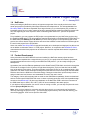
NetFusion Libero Starter Project Helper
V1.1 – January 2015
NetFusion Libero Starter
Project Helper
User Guide
1
NetFusion Libero Starter Project Helper
V1.1 – January 2015
Table of Contents
1
INTRODUCTION ................................................................................................................................... 6
1.1 LIBERO SOC/IDE VERSION 11.X DERIVATIVES..................................................................................... 6
1.2 INSTALLATION..................................................................................................................................... 7
1.3 STARTING A PROJECT AND BASIC UNDERSTANDING ............................................................................. 8
1.3.1
Libero 11.X IDE First Launch .................................................................................................. 8
1.4 NETFUSION ........................................................................................................................................ 9
1.5 PRODUCT DEVELOPMENT ................................................................................................................... 9
1.6 DOCUMENTATION CHECKLIST ............................................................................................................ 10
2
DOWNLOADING NEW IP CORE(S) INTO THE LIBERO IDE INSTALLATION ................................ 12
3
NETFUSION LIBERO I/O ASSIGNMENTS ........................................................................................ 13
4
NETFUSION LIBERO 11.X IDE/SOC TOP-LEVEL ............................................................................ 15
4.1
4.2
4.3
4.4
4.5
4.6
4.7
4.8
4.9
4.10
4.11
4.12
4.13
4.14
4.15
4.16
4.17
4.18
5
NETFUSION ARM CORTEX MSS DEFAULT CONFIGURATION .................................................... 38
5.1
5.2
5.3
5.4
5.5
5.6
5.7
5.8
6
EMCRAFT SYSTEMS .......................................................................................................................... 18
ULPI/UTMI OTG USB..................................................................................................................... 18
CORESF2RESET.............................................................................................................................. 19
FCCC ............................................................................................................................................. 20
COUNTER / GPIO ............................................................................................................................. 22
COREGPIO ..................................................................................................................................... 23
COREUARTAPB ............................................................................................................................... 24
CORESPI0, 1 ................................................................................................................................... 25
TEMPERATURE SENSOR GLUE LOGIC ................................................................................................ 26
COORDINATED RESET ................................................................................................................ 27
BIBUF ........................................................................................................................................ 28
CORESF2CONFIG ........................................................................................................................ 29
CORE AXI ................................................................................................................................... 30
CORE AHB-LITE .......................................................................................................................... 31
CORE APB3 ................................................................................................................................ 32
AXI, AHB-LITE & APB3 DEFAULT MEMORY MAPPED SETTINGS ..................................................... 33
UNUSED LOGIC BLOCK ................................................................................................................. 36
SMARTFUSION2 MSS .................................................................................................................. 37
MDDR............................................................................................................................................. 39
USB ................................................................................................................................................ 40
ETHERNET ....................................................................................................................................... 41
MSS_CCC ...................................................................................................................................... 42
RESET CONTROLLER ...................................................................................................................... 42
FIC_0.............................................................................................................................................. 43
FIC_1.............................................................................................................................................. 44
FIC_2 (PERIPHERAL INITIALIZATION) ................................................................................................. 45
ADDING IP CORES FROM VERILOG/VHDL ..................................................................................... 46
2
NetFusion Libero Starter Project Helper
V1.1 – January 2015
6.1 IMPORTING SOURCE FILES ................................................................................................................ 46
6.2 INSTANTIATING INTO THE FABRIC ....................................................................................................... 47
6.2.1
Building and Synthesizing the NetFusion Design ................................................................. 48
7
USING FLASHPRO4 IDE TO PROGRAM NETFUSION .................................................................... 50
8
REFERENCES .................................................................................................................................... 52
9
CONTACT ........................................................................................................................................... 53
10
DOCUMENT HISTORY ................................................................................................................. 54
3
NetFusion Libero Starter Project Helper
V1.1 – January 2015
List of Figures
Figure 1 - Libero 11.X IDE Boot-Up Screen............................................................................................................8
Figure 2 - Libero Updating IP Core in the Vault ................................................................................................... 12
Figure 3 - Example of Top List I/O Ball Assignments .......................................................................................... 13
Figure 4 - Example of Bottom List I/O Ball Assignments .................................................................................... 14
Figure 5 - Selecting the I/O Constraints ................................................................................................................ 14
Figure 6 - NetFusion Top-Level Sheet................................................................................................................... 15
Figure 7 - Lower-Level SOM sheet MSS block .................................................................................................... 16
Figure 7 - Screenshot of Lower-Level SOM sheet of the StartPack Libero Project ........................................ 17
Figure 9 - ULPI/UTMI USB Converter IP Core ..................................................................................................... 18
Figure 10 - SmartFusion2 Reset Controller IP Core ............................................................................................ 19
Figure 11 - Clock PLL Macro Core ......................................................................................................................... 20
Figure 12 - PLL Clock Macro Settings ................................................................................................................... 21
Figure 13 - Temperature Sensor Logic .................................................................................................................. 22
Figure 14 - Main PCB GPIO Interface with APB bus from the ARM Processor MSS block .......................... 23
Figure 15 - RS485 UART IP core ........................................................................................................................... 24
Figure 16- Stereo Audio Line IN & Line OUT ....................................................................................................... 25
Figure 16- Temp Sensor Counter Logic ................................................................................................................ 26
Figure 16- Customized RESET logic ..................................................................................................................... 27
Figure 17 - Bi-Directional Fabric Macros for input/output signals ...................................................................... 28
Figure 18 - APB feedback Bus for Peripheral Configuration by Software ........................................................ 29
Figure 19 - AMBA Memory Interfaces from ARM for an AXI bus ...................................................................... 30
Figure 19 - AMBA Memory Interfaces from ARM for an AHB-Lite bus ............................................................. 31
Figure 19 - AMBA Memory Interfaces from ARM for the APB3 fixed bus used for the UART, GPIO and
Counter Peripherals .......................................................................................................................................... 32
Figure 19 – Editing the APB3 core settings. ......................................................................................................... 32
Figure 20 - Default AXI Configuration .................................................................................................................... 33
Figure 21 - Default AHB-Lite Configuration .......................................................................................................... 34
Figure 22 - Default APB Configuration .................................................................................................................. 35
Figure 23 - Unused Block in NetFusion SOM ....................................................................................................... 36
Figure 24 - SOM Module of the ARM MSS ........................................................................................................... 37
Figure 25 - Exploded View of the Modules in the NetFusion ARM MSS .......................................................... 38
Figure 26 - MDDR MSS Controlling LPDDR Memory with AXI from Fabric .................................................... 39
Figure 27 - USB OTG UTMI Host Controller ........................................................................................................ 40
Figure 28 - MSS MAC for 10/100 Ethernet Using SOM PHY ............................................................................ 41
Figure 29 - MSS CCC Divider from the CLK_BASE with-in ARM Sub-System .............................................. 42
Figure 30 - Reset MSS Module .............................................................................................................................. 42
Figure 31 - AHB/APB Fabric Interface [1] ............................................................................................................. 43
Figure 32 - APB3/AHB-Lite Fabric Interface [2] ................................................................................................... 44
Figure 33 - APB Peripheral Hardware Configuration........................................................................................... 45
Figure 34 - Importing a single Verilog/VHDL file into the NetFusion Libero Project ....................................... 46
Figure 35 - Instantiating an Imported IP Core in your Fabric Design ................................................................ 47
Figure 36 - Selecting Full NetFusion Synthesis and FPGA Programming ....................................................... 49
Figure 36 – Opening screen of FlashPro IDE ....................................................................................................... 50
Figure 36 – Microsemi FlashPro4 ribbon connection .......................................................................................... 51
Figure 36 – FlashPro Programming Screen ......................................................................................................... 51
4
NetFusion Libero Starter Project Helper
V1.1 – January 2015
About This Document
This specification introduces the NetFusion baseboard’s Libero IDE starter project. Whilst the project ZIP
binary is provided as a downloadable target to the PCB, using the open-source IP project as a start point
will aid and help the user’s intended functional product, and allow for a start-point in their design
customization process.
Intended Audience
This document is fully intended to be viewed and reference by Nine Ways customers using the
technology for larger designs and projects.
5
NetFusion Libero Starter Project Helper
V1.1 – January 2015
1 Introduction
Microsemi design and manufactured the SmartFusion2 FPGA. Libero is the IDE software for
programming and synthesizing IP cores. Along with the bundle of uClinux firmware compilation tools, this
is the heart of the NetFusion design process for Users.
1.1
Libero SoC/IDE Version 11.x Derivatives
Microsemi's Libero ® IDE software release for designing with Microsemi Rad-Tolerant FPGAs, Antifuse
FPGAs and Legacy & Discontinued Flash FPGAs and managing the entire design flow from design entry,
synthesis and simulation, through place-and-route, timing and power analysis. PCN 1108: Silicon Family
Support in Libero IDE.
Libero IDE Software Features:
●
Powerful project and design flow management
●
Full suite of integrated design entry tools and methodologies:
● SmartDesign graphical SoC design creation with automatic abstraction to HDL
● IP Core Catalog and configuration
● User-defined block creation flow for design re-use
●
Synplify Pro ME synthesis fully optimizes Microsemi FPGA device performance and area
utilization
●
Synphony Model Compiler ME performs high-level synthesis optimizations within a Simulink®
environment
6
NetFusion Libero Starter Project Helper
V1.1 – January 2015
●
Modelsim ME VHDL or Verilog behavioral, post-synthesis and post-layout simulation capability
●
Physical design implementation, floor planning, physical constraints, and layout
●
Timing-driven and power-driven place-and-route
●
SmartTime environment for timing constraint management and analysis
●
●
SmartPower provides comprehensive power analysis for actual and "what if" power scenarios
Interface to FlashPro programmers
●
Post-route On Chip Debug Tools and Identify ME debugging software for Microsemi flash designs
●
Silicon Explorer II debugging software for Microsemi antifuse designs
1.2
Installation
Libero software is downloadable for free from http://www.microsemi.com/products/fpgasoc/designresources/design-software/libero-soc#downloads. Some Libero features are optional during
installation.
You can minimize the disk space required by only installing tools you use.
You must have a license to run Libero; the license type that you obtain determines what devices you can
use and what IP is included. The following license types exist for Libero:
• Libero Platinum (All devices and RTL IP Bundle)
• Libero Gold (Limited devices and Obfuscated IP Bundle)
View the complete descriptions of the above Libero installations at
http://www.microsemi.com/products/fpga-soc/design-resources/design-software/libero soc#licensing.
View the IP Bundle contents at http://www.microsemi.com/products/fpga-soc/design-resources/ip-cores.
Libero installation is covered in "Installing Libero Software" on page 16.
Note: You must have Admin rights on the installation machine to install Libero SoC.
7
NetFusion Libero Starter Project Helper
V1.1 – January 2015
1.3
Starting a Project and Basic Understanding
Before attempting to modify or implement any project in Libero, it is advised that you download and read
the following PDF references:
System on Chip installation:
Libero SoC v11.X User's Guide
Libero SoC Quick Start Guide for Software v10.0
Integrated Development Environment installation:
Libero IDE and Software Installation and Licensing Guide
Libero IDE License Troubleshooting Guide
(Note: Press CNTL and click to download the links)
1.3.1 Libero 11.X IDE First Launch
Figure 1 - Libero 11.X IDE Boot-Up Screen
8
NetFusion Libero Starter Project Helper
V1.1 – January 2015
1.4
NetFusion
When purchasing any NetFusion variant, an important component of the overall product is the Libero
starter project that is provided by Nine Ways Research & Development Ltd. This is downloadable from
Nine Ways R&D Ltd and when expanded into a target directory on your development PC, provides an
immediate project for your needs. Instead of having to start and debug creating an ARM sub-system with
all of the supporting IP cores required to have a functioning NetFusion PCB – just use the provided
project.
From installation, you can program the IDE project once synthesized into your NetFusion product using
the FlashPro4 USB device. This will provide the standard functionality in the Smartfusion2 FPGA fabric on
the M2S-SOM-F484 SOM (System-On-Module) to see a working project. In the software bundle to this
product, the uClinux device drivers will drive and control the hardware on the NetFusion PCB through the
IP cores in this project for the FPGA fabric.
Users can contact Nine Ways R&D for special functionality to be developed and deployed, but this serves
as an addition to this starter Libero 11.X IDE project. Moreover, in conjunction with MorethanIP GmbH,
customized and locked down projects can be tailored for customer requests but that also is separate to
this project.
1.5
Product Development
At the point where the Libero IDE/SoC has been installed, the NetFusion starter project has been
downloaded and exploded into a target directory on your PC, the project has been loaded, synthesized,
programmed and shown to be running on the NetFusion PCB product – you are ready to begin your
development.
As standard, the main fast Ethernet pathways into the SmartFusion2 FPGA fabric are wired in through the
FPGA ball I/O, assigned in the I/O editor, brought down through the Top-Level and then into the SOM
level of the design in the project. They then terminate at a dummy IP core for all un-assigned wires – this
makes life a lot easier for the developer knowing that all the NetFusion traces coming into the M2S-SOMF484 are wired into the SOM level of the fabric design. Changes are therefore quick and easy to then reassign in that lower level sheet to new instantiated IP cores of the user’s choice.
The category of wires left terminated and not used are the GMII Ethernet pathways. Users can download
and use Vendor specific MAC/SWITCH cores or chose to privately purchase cores from reputable designhouses such as MorethanIP. All other used hardware on the NetFusion PCB is wired and connected in
the SOM sheet layer to GPIO, SPI, UART, USB, I2C etc as standard in the starter project.
If you decide to write and author your own IP cores in Verilog or VHDL, you can drop and place the code
into the \[Project Dir]\hdl\ directory.
Note: Once you have started to customize and tailor the project to your own needs and functionality,
obviously renaming the project is easy – just rename the project directory and inside that directory, just
rename the [.prj] file. Close and re-open the Libero IDE.
9
NetFusion Libero Starter Project Helper
V1.1 – January 2015
1.6
Documentation Checklist
Libero SoC User’s Guide
Explains how to use the Libero SoC Project Manager, including Designer and SmartDesign.
SmartFusion2 and IGLOO2 SmartTime, I/O Editor and ChipPlanner User’s Guide
Provides details about using SmartTime for timing analysis, placing macros, floor planning and viewing
chip resources for SmartFusion2
MultiView Navigator User’s Guide (includes documentation for ChipPlanner,
PinEditor, I/O Attribute Editor, and NetlistViewer in MVN)
Provides details about placing macros, floor planning, and viewing chip resources; contains information
about using NetlistViewer in the MultiView Navigator to view your netlist; describes how to use the
PinEditor in MVN; describes how to use the I/O Attribute Editor tool.
Design Constraints User’s Guide
Provides a complete reference for creating and modifying timing, physical, and netlist optimization
constraints in Libero SoC, including families and file formats supported for each constraint. It also
describes how to create and modify I/O constraints with the I/O Attribute Editor, before compiling your
design.
SmartPower User’s Guide
Describes how to use SmartPower for power analysis.
SmartTime User’s Guide
Describes how to use SmartTime for timing analysis and how to set clock constraints.
Tcl Command Reference
Lists all the Tcl commands and parameters for the Microsemi software tools.
Analog System Builder, FlashROM and Flash Memory System Builder User’s
Guide
Describes how to use the FlashROM generator, the Analog System Builder, and the Flash Memory
System Builder.
SmartGen Cores Reference Guide
Provides descriptions of cores that can be generated from the Catalog using the SmartGen Core Builder.
10
NetFusion Libero Starter Project Helper
V1.1 – January 2015
FlashPro User’s Guide
Contains information about how to program your devices using the FlashPro software and device
programmer. FlashPro is not available on UNIX.
SmartFusion2 and IGLOO2 Macro Library Guide
Provides descriptions of Microsemi library elements for the Microsemi SmartFusion2 and IGLOO2 device
families. Symbols, truth tables, and module counts (if appropriate) are included for all macros.
IGLOO, ProASIC3, SmartFusion and Fusion Macro Library Guide
Provides descriptions of Microsemi library elements for Microsemi SmartFusion, Fusion, ProASIC3 and
ProASIC3E device families. Symbols, truth tables, and module counts (if appropriate) are included for all
macros.
SmartFusion2 and IGLOO2 Block Flow User’s Guide
Describes how to create and integrate Blocks in Libero SoC for SmartFusion2 and IGLOO2.
VHDL Vital Simulation Guide
Contains information about using the ModelSim to simulate designs for Microsemi SoC devices.
Verilog Simulation Guide
Contains information about interfacing the FPGA development software with Verilog simulation tools.
ViewDraw User’s Guide
Describes how to create designs in ViewDraw using menu commands, toolbar buttons, and by selecting
and entering information on dialog boxes. ViewDraw for Microsemi is not available on UNIX.
ModelSim ME Book Case
Contains a User’s Manual, Command Reference, and Tutorial. These guides contain details about using
ModelSim ME, Libero’s integrated simulation tool. Refer to the documentation included with ModelSim
ME for more information. ModelSim ME documentation is also available at:
http://www.microsemi.com/products/fpga-soc/design-resources/design-software/liberosoc#
Documents
Synopsys Synplify Pro ME
Documents include release notes, user’s guide, tutorial, reference manual, and license configuration and
set-up. Refer to the documentation included with Synopsys Synplify Pro for more information. Synopsys
Synplify Pro ME documentation is also available at:
http://www.microsemi.com/products/fpga-soc/design-resources/design-software/libero-soc#documents
11
NetFusion Libero Starter Project Helper
V1.1 – January 2015
2 Downloading New IP Core(s) into the Libero IDE Installation
Figure 2 - Libero Updating IP Core in the Vault
When you first load the NetFusion starter project into the IDE, the most likely occurrence to happen is a
system message warning you to update “New IP Cores”. This is because the design includes cores that
you possibly do not have on your vault on your local hard drive.
Click “YES” to proceed and let the download process complete. Note: this may take several minutes and
you MUST have a network connection and gateway to the internet.
12
NetFusion Libero Starter Project Helper
V1.1 – January 2015
3 NetFusion Libero I/O Assignments
The NetFusion Libero starter project is delivered already with the I/O balls of the FPGA assigned ready
for the user. These all correspond with the pin-out tracking assignments on the NetFusion PCB product.
This means that you will not have to consider any of these assignments unless you are planning any
major changes to the inherent default design.
This is very unlikely as you would need then to request changes to the PCB design. However, this section
highlights the assignments in case you also want to make minor changes to the direction of the port,
default output values and/or change internal SmartFusion2 FPGA pull-up values.
Figure 3 - Example of Top List I/O Ball Assignments
13
NetFusion Libero Starter Project Helper
V1.1 – January 2015
Figure 4 - Example of Bottom List I/O Ball Assignments
The I/O assignment dialog is selected from the I/O Constraints anchor in Place and Route section (below)
Figure 5 - Selecting the I/O Constraints
14
NetFusion Libero Starter Project Helper
V1.1 – January 2015
4 NetFusion Libero 11.X IDE/SoC Top-Level
Within the NetFusion starter Libero project, the M2S_SOM Top-Level sheet illustrates the lower modules
to the design just before the I/O ports go out to the real-world PCB. The ports labeled in this sheet
correspond to the I/O assignments (shown in the previous section). This sheet is effectively the linkage
from the inner SOM design (see next section) up to the I/O balls of the SmartFusion2 FPGA.
Figure 6 - NetFusion Top-Level Sheet
When lower level SOM sheets are built and prepared, they propagate information up automatically to this
higher sheet. New ports suddenly appear and you must then compile this sheet before the main
synthesis.
Note: you can instantiate normal IP cores into this top sheet if you wish and it makes sense according to
your design requirements. This is just the starter project so everything by default is kept in the lower SOM
module. But this can change rapidly as your customization starts to take effect.
The lower SOM sheet of the NetFusion starter Libero project contains all of the default designs and
linkage.
15
NetFusion Libero Starter Project Helper
V1.1 – January 2015
This SOM sheet lower layer contains the ARM Cortex-M3 MSS block and then all of the necessary
associated IP core blocks to allow the processor, the Emcraft SOM and the wider surrounding NetFusion
baseboard hardware to operate and be accessed.
Figure 7 - Lower-Level SOM sheet MSS block
The next screenshot shows a rats-nest but the following sub-sections illustrates the different parts in more
detail. Note: Incidentally, the largest module center-left is the MSS ARM cortex processor (zoomed
above).
16
NetFusion Libero Starter Project Helper
V1.1 – January 2015
Figure 8 - Screenshot of Lower-Level SOM sheet of the StartPack Libero Project
17
NetFusion Libero Starter Project Helper
V1.1 – January 2015
4.1
Emcraft Systems
The (above) figure overview encapsulates the whole of the NetFusion SOM sheet. However, it was built
on the basic project supplied currently by Emcraft. They designed and developed the M2S-SOM-F484
that is housed on the NetFusion baseboard PCB.
Various IP cores were added to accommodate the need to support and facilitate the vast multitude of
NetFusion’s PCB hardware available to the ARM MSS sub-system in the SmartFusion2 FPGA on the
Emcraft M2S-SOM-F484 housed on NetFusion as one product. As the MSS can only drive and support
some of the pins on the SOM unit, there was a requirement therefore, to add more IP cores in the fabric
to interface through the I/O assignments to the PCB hardware not connected directly to the MSS.
These additional cores and the default statutory parts of the SOM design in the Fabric are described in
the sub-sections (below).
4.2
ULPI/UTMI OTG USB
On the SmartFusion2 F484 package that is used with Emcraft's M2S-SOM-F484 System-On-Module, the
ULPI MSS interface is not supported. However, the UTMI OTG USB signals are supported. As the track
routing and the IC USB device on the NetFusion PCB support ULPI, an IP core in the fabric is require to
convert between the two different USB On-The-Go protocols and signals. This has been instantiated as
[ulpi_port_0].
This OTG core was used from OpenCores at http://www.opencores.com and resides in the NetFusion
starter project's hdl/ sub-directory.
Figure 9 - ULPI/UTMI USB Converter IP Core
18
NetFusion Libero Starter Project Helper
V1.1 – January 2015
4.3
CoreSF2Reset
This core is used to co-ordinate the reset across all of the FPGA in strict timed sequence. It is important
for the peripheral logic to be released after the MSS ARM processor and then the fabric logic following
the MSS. This is a standard Libero ACTEL core from the vault.
The EXT_RESET_OUT signal is routed out of the FPGA device to the NetFusion PCB. The input to this
core is the POWER_ON_RESET_N. This core was instantiated as [CoreSF2Reset_0].
Figure 10 - SmartFusion2 Reset Controller IP Core
19
NetFusion Libero Starter Project Helper
V1.1 – January 2015
4.4
FCCC
The entire FPGA sub-system comprising of the MSS ARM processor and the main fabric run on clocks all
generated from this core. It is the main coordination of the clock lines that are distributed. The input is
12MHz from an off-chip crystal/IC. The CCC PLL divides down the 12MHz source by 12 to 1MHz. Then
this is multiplied up by differing amounts for GL0. You can add more clock PLL lines as you wish when
you are modifying the design.
Figure 11 - Clock PLL Macro Core
The core as been instantiated as [FCCC_0]. There is also a LOCK output signal that is used by the MSS
to determine when the PLL has settled and locked onto the desired output frequencies. All clock outputs
are digital square waves.
20
NetFusion Libero Starter Project Helper
V1.1 – January 2015
Figure 12 - PLL Clock Macro Settings
Output signal GL0 is distributed to the memory bus and the MSS ARM block. The main base clock
frequency for the 166MHz ARM processor is scaled up inside the MSS block.
21
NetFusion Libero Starter Project Helper
V1.1 – January 2015
4.5
Counter / GPIO
NetFusion PCB has an on-board temperature sensor. The output of which is a square wave signal that
has a frequency is equivalent to degrees Kelvin (down to absolute zero). This signal is routed into the
SmartFusion2 FPGA fabric and clocks the 16-bit counter [counter16_0]. The counter's 16-bit output value
is wired into GPIO input [coreGPIO_1] which is memory addressable from the ARM uClinux applications.
This serves as a simple 32-bit memory location to read and makes the software algorithm for determining
the temperature incredibly simple.
Note: the memory interface from the ARM MSS is an APB interface.
Figure 13 - Temperature Sensor Logic
22
NetFusion Libero Starter Project Helper
V1.1 – January 2015
4.6
CoreGPIO
The vast majority of the hardware on the NetFusion PCB is connected through this core. The obvious
exceptions are the Ethernet pathways, RS485 UART and the SPI audio input/output. However, all of the
I2C, Relays, I/O expanders, Real-Time clock IC, voltage monitor, expansion I/O and all other slow speed
communications are handled through this [coreGPIO_0] instantiated block.
It is visible to the ARM MSS processor via an APB interface memory bus. Lines can be configured as
inputs or outputs and are all individually controlled and observed by the uClinux UIO device driver.
Figure 14 - Main PCB GPIO Interface with APB bus from the ARM Processor MSS block
23
NetFusion Libero Starter Project Helper
V1.1 – January 2015
4.7
CoreUARTapb
As there is no way in the SmartFusion2 ARM MSS block for standard UART connections (/dev/ttyS0 and
/dev/ttyS1 already used) the RS484 PCB hardware has to be controlled and handled from a fabric UART
core. This was instantiated as [CoreUARTabp_0] and has an APB connection to the MSS block.
The uClinux device driver for this hardware access the core as a block of memory and the FIFO RX and
TX data is stored in the fabric core. The RX ad TX signals to the NetFusion PCB hardware are TTL levels
and then get converted to RS485 voltage signals in the electronics.
Figure 15 - RS485 UART IP core
24
NetFusion Libero Starter Project Helper
V1.1 – January 2015
4.8
CoreSPI0, 1
Running as separated IP cores instantiated in the fabric to achieve higher speed sampling by SPI
software are SPI blocks. These are [CORESPI_0 and CORESPI_1] and use an APB interface to the ARM
MSS sub-system. Each core has a 4-wire SPI bus routed out of the FPGA to the wider NetFusion PCB
hardware.
These SPI interfaces connect to DAC and ADC stereo IC devices. This allows for audio to be sent and
received from the PCB and the digital samples can be processed by the ARM processor from network
traffic if necessary. SPI is used as it is full duplex and runs at over 1MHz during operation. However,
bottlenecks in the processor application code and also human audible hearing limitations keep realistic
sampling operations around < 10KHz.
Figure 16- Stereo Audio Line IN & Line OUT
25
NetFusion Libero Starter Project Helper
V1.1 – January 2015
4.9
Temperature Sensor Glue Logic
The baseboard temperature sensor IC is mounted under the Emcraft SOM daughter card and
monitors the temperature of the FPGA that can often be demanded to perform high switching tasks in
the fabric of the device.
The sensor produces an output square wave in which the frequency in Hz is equal to the degrees
Kelvin on the baseboard. This is routed into the FPGA and the fabric and is represented on the SOM
design sheet as “TEMP_SENSOR”. This in turn, clocks the [counter16_0] which has a 16-bit register
output, and can be read into the ARM software environment via the [CoreGPIO_1] APB3 core.
Although this read value wraps around 16-bit values, the software can use a one second timer to run
comparisons and then calculate the temperature in Kelvin.
Figure 17- Temp Sensor Counter Logic
26
NetFusion Libero Starter Project Helper
V1.1 – January 2015
4.10 Coordinated RESET
The customized IP core instantiated as [mtip_reset_1] coordinates a longer reset pulse than the power on
reset core often provides. The source [SYSRESET_0] feeds into the [mtip_reset_1] which then provides
an output to the whole SOM sheet design. This includes the ARM MSS block, memory cores, GPIO and
all peripherals.
Figure 18- Customized RESET logic
27
NetFusion Libero Starter Project Helper
V1.1 – January 2015
4.11 BIBUF
Throughout the NetFusion starter project's fabric logic design is scattered around Bi-Directional macros.
These convert conveniently any IN/OUT data flow when the RX and TX are kept separate in the IP cores.
The output side always routes up out of the SmartFusion2 FPGA to the NetFusion PCB hardware where
the signals are capable of input/output operation using pull-up resistors combining tri-state operation.
The instantiated BIBUFs are illustrated in the Figure (below).
They are controlled by an output enable signal that drives the state of the output pin. An example of the
need for bi-directional signal operation is MDIO for the Marvell PHY and the SDA data line for ALL I2C
buses on the NetFusion PCB.
Figure 19 - Bi-Directional Fabric Macros for input/output signals
28
NetFusion Libero Starter Project Helper
V1.1 – January 2015
4.12 CoreSF2Config
The SmartFusion2 MSS processor sub-system always as standard has a default CoreSF2Config block
which loops back an APB bus out and then back into the MSS block. This seems at first strange and can
be very confusing. However, it is the inherent architecture of the FPGA ASIC area that most of the
peripheral devices inside the MSS ARM processor core are not actually controlled by the selections made
in the Libero 11.X IDE. It is the software in U-boot during boot-up that configures. If say for instance, an
AHB-Lite interface is selected in Libero, then this does not configure the SmartFusion2 FPGA itself. It
saves a configuration file that can be included by software in either bare-metal programming or the u-boot
from Emcraft uClinux environment.
Only when the boot-up code access the APB feedback bus via [CoreSF2Config_0] and manipulates
hardware peripheral memory address does the peripherals in the MSS get the correct mode of operation
intended for them.
Figure 20 - APB feedback Bus for Peripheral Configuration by Software
29
NetFusion Libero Starter Project Helper
V1.1 – January 2015
4.13 Core AXI
In the SOM sheet of the design, there exists an IP core used for AXI memory bus accessing. It does not
have any memory core attached as default when you open and view the project initially. However, this
stub is the user to use to attach to any AXI memory bus interface IP core that they wish to use. All of the
signals not used are either tied LOW (or HIGH if required) for input signals, and marked as unused if
output signals.
The AXI core is instantiated as [COREAXI_0] in the SOM sheet design and currently has no intended
functionality other than providing the user with a hook access point to the AXI ARM MSS system. The AXI
core has an associated location in the overall ARM AHB matrix memory map and therefore attached IP
cores can then have hardware address visibility from the ARM processor software environment.
Figure 21 - AMBA Memory Interfaces from ARM for an AXI bus
30
NetFusion Libero Starter Project Helper
V1.1 – January 2015
4.14 Core AHB-Lite
In the SOM sheet of the design, there exists an IP core used for AHB-lite memory bus accessing. It does
not have any memory core attached as default when you open and view the project initially. However, this
stub is the user to use to attach to any AHB-lite memory bus interface IP core that they wish to use. All of
the signals not used are either tied LOW (or HIGH if required) for input signals, and marked as unused if
output signals.
The AHB core is instantiated as [CoreAHBLite_0] in the SOM sheet design and currently has no intended
functionality other than providing the user with a hook access point to the AHB ARM MSS system. The
AHB core has an associated location in the overall ARM AHB matrix memory map and therefore attached
IP cores can then have hardware address visibility from the ARM processor software environment.
Figure 22 - AMBA Memory Interfaces from ARM for an AHB-Lite bus
31
NetFusion Libero Starter Project Helper
V1.1 – January 2015
4.15 Core APB3
The SOM sheet design has a useful APB3 core instantiated as [CoreAPB3_0] which is by default, used
to collate and connect various important cores to the ARM MSS memory map. Currently the temperature
sensor counter GPIO (CoreGPIO_1), the main GPIO core (CoreGPIO_0), the UART core
(CoreUARTapb_0), the two audio SPI cores (CORESPI_0, CORESPI_1) and finally the SPI baseboard
device IC chip select logic (CoreGPIO_2).
Figure 23 - AMBA Memory Interfaces from ARM for the APB3 fixed bus used for the UART, GPIO
and Counter Peripherals
Although the APB3 core is used extensively, this can be extended to allow any user instantiated core to
be connected by adding another slave line to the core. This can be obtained by double-clicking on the
core and editing the settings.
Figure 24 – Editing the APB3 core settings.
Please Note: the previous AXI and AHB-Lite cores can be edited and changed with exactly the same
method by double-clicking on the cores themselves.
32
NetFusion Libero Starter Project Helper
V1.1 – January 2015
4.16 AXI, AHB-Lite & APB3 default Memory Mapped Settings
Figure 25 - Default AXI Configuration
33
NetFusion Libero Starter Project Helper
V1.1 – January 2015
Figure 26 - Default AHB-Lite Configuration
34
NetFusion Libero Starter Project Helper
V1.1 – January 2015
Figure 27 - Default APB Configuration
Important Note: as a Libero 11.X designer and developer, the user may change these defaults and
added or remove memory accessible IP cores to/from the fabric.
35
NetFusion Libero Starter Project Helper
V1.1 – January 2015
4.17 Unused Logic Block
Specifically to the NetFusion starter project, is the instantiated dummy block that allows all of the wires
and signals coming into the SmartFusion2 FPGA fabric from the outside PCB that are not connected to IP
cores to terminate here. Most of these are the Ethernet signals and pathways of the GMII.
In order to make it easier for a user to instantiate their own IP cores and then connect the unused signals,
this starter project has had to include the unused signals at the I/O level of the FPGA, bring them down
through the Top-Level then into the SOM sheet. They then terminate at the [unsused_block_0].
Figure 28 - Unused Block in NetFusion SOM
36
NetFusion Libero Starter Project Helper
V1.1 – January 2015
Libero 11.X and SynplifyPro do not like un-terminated signals and it will remove them from the I/O
assignments if they were not routed by default to this block.
As you require a signal terminated at this block, simply un-route it from the unused block and then reassign to your new IP core using the "quick connect" option. However, make sure that if it was an output
of the unused block, to assign the pin left vacant as "unused", or if an input then set the attribute to "tie
LOW".
The output signal "REGSPR" is just a necessary signal that is not assigned any I/O ball of the FPGA and
is used internally with-in the core to stop Libero 11.X optimization occurring and removing the inputs of
this block from the I/O assignments. Do not remove this output.
4.18 SmartFusion2 MSS
In the SOM layer sheet of the NetFusion starter project, the MSS ARM processor main core is situated in
the middle and is shown (below). If you double-click on the MSS block it will expanded and create another
window in Libero 11.X on screen.
Note: Refer to the next section for the MSS documentation.
Figure 29 - SOM Module of the ARM MSS
37
NetFusion Libero Starter Project Helper
V1.1 – January 2015
5 NetFusion ARM Cortex MSS Default Configuration
Figure 30 - Exploded View of the Modules in the NetFusion ARM MSS
The MSS in the heart of the SmartFusion2 NetFusion design is defaulted and set to the exact current
needs of the PCB product. Modules I2C1, I2C2, CAN, GPIO, RTC and PDMA are disabled currently but
there is nothing stopping the user from enabling and wiring out the modules to the SOM sheet.
The blue modules are currently enabled for the NetFusion design as they have functional requirements
and the signals are wired out to the SOM sheet then if necessary up to the I/O assignments then out of
the FPGA device itself.
38
NetFusion Libero Starter Project Helper
V1.1 – January 2015
5.1
MDDR
Figure 31 - MDDR MSS Controlling LPDDR Memory with AXI from Fabric
The MDDR has been configured to use a single data rate LPDDR SDRAM device on the M2S-SOM-F484
using 16-bit data width. Priority has been given to the AXI master interface from the fabric where the
default connection is to the AMBA DMA Controller for 3rd party MACs and Ethernet SWITCH.
If you do not wish to keep the DMA Controller or any AXI interface for that matter, then you can de-select
the Fabric Interface and the SOM sheet will adjust accordingly. Important: You will have to remove and
delete the instantiated DMA Controller however.
Note: NetFusion has to follow the architecture of the SOM-F484 so this is primarily based upon the
Emcraft starter project for this block.
39
NetFusion Libero Starter Project Helper
V1.1 – January 2015
5.2
USB
Figure 32 - USB OTG UTMI Host Controller
NetFusion does utilize on the PCB hardware an OTG USB interface. In the fabric, the ULPI is converted
to UTMI and then connected to this MSS internal block.
The ARM uClinux application code will be able to access this USB block as a block of memory registers
and device drivers will be able to control the USB OTG as a USB stack.
Note: the UTMI signals do not get routed to the I/O pins directly but the fabric for the use of the
ULPI/UTMI converter IP core.
40
NetFusion Libero Starter Project Helper
V1.1 – January 2015
5.3
Ethernet
Figure 33 - MSS MAC for 10/100 Ethernet Using SOM PHY
This is a very strategic and important module in the MSS of the SmartFusion2 of NetFusion. The 4th
RJ45 Ethernet connector on the NetFusion PCB is routed directly to the PHY on the M2S-SOM-F484
which in turn, connects into the SmartFusion2 FPGA and directly into the ARM MSS.
Special Note: on the SFP SERDES variant of NetFusion PCB, the dedicated SOM RJ45 is the 2
on the dual HALO.
nd
port
Once in the MSS, the Ethernet MAC receives the connections which then provide a memory interface
internally for the ARM uClinux device drivers for the network interfaces.
Note: The connections route to the fabric before going up through to the I/O assignments.
It is important to emphasize that with NetFusion, three of the RJ45 10/100/1000 ports use a separate
Marvell PHY that routes into the SOM sheet of the starter project and terminates at [unused_block_0].
Special Note: on the SFP SERDES variant, two of the 1Gb/s ports are 1.25Gb/s SERDES.
However, the dedicated 4th port always allows MSS and ARM gateway access to the network. Benefits of
this architecture can provide IP routing functionality for the user. This is due to the link between the MSS
MAC and the fabric MACs only being visible to each other in the uClinux IP stack of the kernel.
41
NetFusion Libero Starter Project Helper
V1.1 – January 2015
5.4
MSS_CCC
Figure 34 - MSS CCC Divider from the CLK_BASE with-in ARM Sub-System
The main 166MHz clock into the MSS from the fabric is configured to be split up and if necessary divided
down to the different areas of the sub-system. It is derived from the Div 2 83MHz from the PLL in the
fabric.
In the case of NetFusion and the StarterPack Libero 11.X IDE project, all peripherals, memory controllers
and fabric interfaces run at half the base clock frequency at 83MHz.
5.5
RESET Controller
Figure 35 - Reset MSS Module
NetFusion by default enables the MSS_RESET_N_F2M, M3_RESET_N and the MSS_RESET_N_M2F
negative reset signals to come in from the SmartFusion2 FPGA fabric.
This gives more functionality to the user. However, if it is not a required functionality when the design is
customized, then they can be de-selected.
42
NetFusion Libero Starter Project Helper
V1.1 – January 2015
5.6
FIC_0
Figure 36 - AHB/APB Fabric Interface [1]
The NetFusion FIC_0 has been chosen to be assigned for the AHB-Lite fabric interface. It is a MASTER
which connects to the SLAVES in the fabric as the ARM processor has complete control.
By default, the AHB-Lite only interfaces to the AMBA DMA Controller used for 3rd party Ethernet IP cores.
Although the DMA Controller uses AXI for the main data throughput, the AHB-Lite is used to access the
configuration registers.
Note: you will observe that Fabric Region 2: 0x7000000 - 0x7FFFFFF has been allocated to the next
FIC_1 block (next sub-section). The configuration on the left panel (above) selects mapping for both
FIC_0 and FIC_1.
NetFusion assigns Fabric Region 2 to the APB memory interface so that the UART, SPI and GPIO can be
accessed in the fabric otherwise only this AHB-Lite interface would be mapped which would severely limit
the NetFusion functionality and capability.
43
NetFusion Libero Starter Project Helper
V1.1 – January 2015
5.7
FIC_1
Figure 37 - APB3/AHB-Lite Fabric Interface [2]
Using the configuration from the previous FIC_0 block (previous), this MSS module enables the APB
interface to access the GPIO, SPI and UART in the NetFusion SmartFusion2 fabric.
Note: this is also an APB Master as the ARM processor has complete control.
44
NetFusion Libero Starter Project Helper
V1.1 – January 2015
5.8
FIC_2 (Peripheral Initialization)
Figure 38 - APB Peripheral Hardware Configuration
As described earlier in this document, the SmartFusion2 FPGA is setup and primarily configured by
boot-up software executed by the ARM processor. This can be bare-metal code or early boot code
from uClinux called u-boot.
This MSS module block enables the signals to connect a feedback APB interface from the ARM
processor to the other peripherals in the MSS itself. It seems an overkill but that is the architecture we
are ruled by it seems.
In the case of NetFusion, we configure the FIC_0 and FIC_1 fabric interface controllers and also select
the AXI Slave interface for the MDDR block.
Important Note: do not ever remove this feature from the design of NetFusion. The system will not
operate if deleted.
45
NetFusion Libero Starter Project Helper
V1.1 – January 2015
6 Adding IP Cores from Verilog/VHDL
6.1
Importing Source Files
Figure 39 - Importing a single Verilog/VHDL file into the NetFusion Libero Project
From time to time, you may want to deviate from the default NetFusion Libero 11.X Starter Project. If you
need to add catalogue cores especially for the fabric macros, then download using the vault.
Also, as illustrated (above), you also may wish to import 3rd party source IP cores. To do this, on the
panel on the left of the Libero IDE, right click on "Create HDL" and then select "Import Files...". This will
bring the Verilog/VHDL into the main system.
You can check if the source code has syntax errors and is valid for the synthesizer (Libero 11.XSynplify
Pro) that Libero 11.X uses. This mechanism enables the NetFusion project to be customized and built on
for a users system requirements.
46
NetFusion Libero Starter Project Helper
V1.1 – January 2015
6.2
Instantiating into the Fabric
Figure 40 - Instantiating an Imported IP Core in your Fabric Design
Whether you wish to instantiate into the SmartFusion2 fabric an imported 3rd party source code core from
VHDL/Verilog or it is from the vault downloaded from ACTEL, the process to get the core into the design
sheets is the same and relatively simple. Even if the core is a macro as part of the ASIC area of the
FPGA, the process is the same no matter what area of the design it involves. Simply move the left panel
to select "Design Hierarchy" and then right click on the listed core of your choice. Select "Instantiate in
M2S_SOM" or whichever sheet is displayed on the right pane of Libero IDE.
The core will appear in the design for you to move and anchor ready for connection routing.
47
NetFusion Libero Starter Project Helper
V1.1 – January 2015
Note: If the core has errors, the error report page will appear and the instantiation will not occur.
6.2.1 Building and Synthesizing the NetFusion Design
∙
Open the Top-Level, SOM and the MSS sheets
∙
Start with the MSS, and right click "Generate Component"
∙
If errors, eliminate then perform previous instruction over again
∙
Once successful, move to the SOM sheet
∙
Right click "Generate Component"
∙
If errors, eliminate then perform previous instruction over again
∙
Once successful, move to the Top-Level sheet
∙
Right click "Generate Component"
∙
If errors, eliminate then perform previous instruction over again
48
NetFusion Libero Starter Project Helper
V1.1 – January 2015
Figure 41 - Selecting Full NetFusion Synthesis and FPGA Programming
Once you are ready to synthesize and program the SmartFusion2 FPGA on the M2S-SOM-F484 housed
on NetFusion, select the option (shown above).
Note: This should take around 20 minutes on a standard Windows XP/7/8 PC. However, larger
customized design will add significant time especially if the design has strict time-constraints
49
NetFusion Libero Starter Project Helper
V1.1 – January 2015
7 Using FlashPro4 IDE to Program NetFusion
Install and make use of FlashPro IDE on Windows XP/7/8 OS to allow for the stand-alone programming of
the baseboard without the need for launching, installing or using the full Libero 11.X SoC IDE.
Figure 42 – Opening screen of FlashPro IDE
Launch the IDE so that you see the (above) screen. Also, if you have just installed the IDE, ensure that
you have also installed the FlashPro4 USB device driver in the Windows Device Manager.
Note: the device driver should be automatically installed with the FlashPro installation (which is
downloadable from the Microsemi website).
50
NetFusion Libero Starter Project Helper
V1.1 – January 2015
Ensure that the NetFusion PCB has the ribbon cable attached from the FlashPro4 USB programmer
(below)
Figure 43 – Microsemi FlashPro4 ribbon connection
On the FlashPro IDE screen, click on New Project.
Enter any project name (and make sure you have write permissions to the selected directory you choose).
Figure 44 – FlashPro Programming Screen
In the drop-down menus, choose Configuration, then select Load Programming File…
Chose your [.STP] file to program NetFusion.
Click on the main PROGRAM button center right of the (above) screen.
Wait for the programming to complete typically after several minutes…
If you cannot select the USB programmer correctly, check it is plugged in and also click on
“Refresh/Rescan for Programmers” button towards the bottom of the screen (above).
Important: once the operation to program NetFusion is complete, the SmartFusion2 FPGA will re-power
and start automatically.
51
NetFusion Libero Starter Project Helper
V1.1 – January 2015
8 References
Please refer to online documented support at the Microsemi reference center.
For M2S-SOM-F484 hardware documents please visit the Emcraft hardware for the SOM-F484.
If you need Libero 11.X references from Emcraft, this will illustrate the default designs that NetFusion was
built from in order to achieve the baseboard functionality.
52
NetFusion Libero Starter Project Helper
V1.1 – January 2015
9 Contact
Nine Ways Research &
Development Ltd
E-Mail
: [email protected]
Internet
: www.nineways.co.uk
UK
Unit A.3, iDCentre, Lathkill House, rtc Business Park
London Road, Derby. DE24 8UP
United Kingdom
Tel
: +44 (0) 1332 258847
FAX
: +44 (0) 1332 258823
53
NetFusion Libero Starter Project Helper
V1.1 – January 2015
10 Document History
Document Change Notices (DCO)
Version
Description
Created/Changed By
Version 1.0
Initial Release according to
Version 1.0
Paul Bates: Nine Ways
17th July 2014
Version 1.1
Updated the pictures of the
cores, tidied up and added
new sections on new cores
that have been included in
the latest StartPack Libero
Project for NetFusion
Paul Bates: Nine Ways
23rd January 2015
Copyright © Nine Ways R&D Ltd 2014. All Rights Reserved.
54
Date