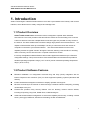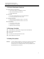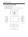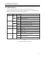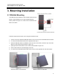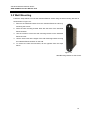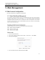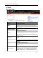
1
Industrial Wireless Ethernet Router APR-3100 Series User Manual V1.0 APR-3100N Series Industrial AP/VPN/Router IEEE 802.11a/b/g/n User Manual Version 1.0 i Industrial Wireless Ethernet Router APR-3100N Series User Manual V1.0 © Copyright 2014 Antaira Technologies, LLC All Rights Reserved This document contains information, which is protected by copyright. Reproduction, adaptation or translation without prior permission is prohibited, except as allowed under the copyright laws. Trademark Information Antaira is a registered trademark of Antaira Technologies, LLC, Microsoft Windows and the Windows logo are the trademarks of Microsoft Corp. NetWare is the registered trademark of Novell Inc. WMM and WPA are the registered trademarks of Wi-Fi Alliance. All other brand and product names are trademarks or registered trademarks of their respective owners. Notice: Copyrights © 2014 by Antaira Technologies, LLC. All rights reserved. Reproduction, adaptation, or translation without prior permission of Antaira Technologies, LLC is prohibited, except as allowed under the copyright laws. Disclaimer Antaira Technologies, LLC provides this manual without warranty of any kind, expressed or implied, including but not limited to the implied warranties of merchantability and fitness for a particular purpose. Antaira Technologies, LLC may make improvements and/or changes to the product and/or specifications of the product described in this manual, without prior notice. Antaira Technologies, LLC will not be liable for any technical inaccuracies or typographical errors found in this guide. Changes are periodically made to the information contained herein and will be incorporated into later versions of the manual. The information contained is subject to change without prior notice. ii Industrial Wireless Ethernet Router APR-3100N Series User Manual V1.0 FCC Warning This equipment has been tested and found to comply with the limits for a Class-B digital device, pursuant to Part 15 of the FCC rules. These limits are designed to provide reasonable protection against harmful interference in a residential installation. This equipment generates, uses, and can radiate radio frequency energy. It may cause harmful interference to radio communications if the equipment is not installed and used in accordance with the instructions. However, there is no guarantee that interference will not occur in a particular installation. If this equipment does cause harmful interference to radio or television reception, which can be determined by turning the equipment off and on, the user is encouraged to try to correct the interference by one or more of the following measures: Reorient or relocate the receiving antenna. Increase the separation between the equipment and receiver. Connect the equipment into an outlet on a circuit different from that to which the receiver is connected. Consult the dealer or an experienced radio/TV technician for help. Caution: Any changes or modifications not expressly approved by the grantee of this device could void the user's authority to operate the equipment. This device complies with Part 15 of the FCC Rules. Operation is subject to the following two conditions: (1) This device may not cause harmful interference, and (2) This device must accept any interference received, including interference that may cause undesired operation. CE Mark Warning This is a Class-B product. In a domestic environment this product may cause radio interference in which case the user may be required to take adequate measures. RF Exposure Warning The equipment complies with FCC RF exposure limits set forth for an uncontrolled environment. The equipment must not be co-located or operating in conjunction with any other antenna or transmitter. ICES 003 Statement This Class B digital apparatus complies with Canadian ICES-003. Industry Canada Statement: This device complies with RSS-210 of the Industry Canada Rules. Operation is subject the following two conditions: (1) This device may not cause harmful interference, and (2) This device must accept any interference received, including interference that may cause undesired operation. iii Industrial Wireless Ethernet Router APR-3100N Series User Manual V1.0 Declaration of Conformity Antaira declares the following: Product Type: Wireless Industrial Router Model No.: APR-3100N conforms to the following product standards: This device complies with the Electromagnetic Compatibility Directive (89/336/EEC) issued by the Commission of the European Community. Compliance with this directive implies conformity to the following European Norms (in brackets are the equivalent international standards.) Electromagnetic Interference (Conduction and Radiation): EN 55022 (CISPR 22) Electromagnetic Immunity: EN 55024 (IEC61000-4-2, 3, 4, 5, 6, 8, 11) Low Voltage Directive: EN 60 950: 1992+A1: 1993+A2: 1993+A3: 1995+A4: 1996+A11: 1997. Therefore, this product is in conformity with the following regional standards: FCC Class B: following the provisions of FCC Part 15 directive, CE Mark: following the provisions of the EC directive. Antaira also declares that: The wireless card in this product complies with the R&TTE Directive (1999/5/EC) issued by the Commission of the European Community. Compliance with this directive implies conformity to the following: EMC Standards: FCC: 47 CFR Part 15, Subpart B, 47 CFR Part 15, Subpart C (Section 15.247); CE: EN 300 328-2, EN 300 826 (EN 301 489-17) Therefore, this product is in conformity with the following regional standards: FCC Class B: following the provisions of FCC Part 15 directive, CE Mark: following the provisions of the EC directive. Industrial Wireless Router Antaira’s Industrial Wireless Ethernet Router User Manual Version 1.0 (November 2014) This manual supports the following models: APR-3100N This document is the current official release manual. Please check our website (www.antaira.com) for any updated manual or contact us by e-mail ([email protected]). iv Industrial Wireless Ethernet Router APR-3100N Series User Manual V1.0 Table of Contents 1. Introduction ................................................................. 1 1.1 Product Overview ............................................... 1 1.2 Product Software Features ................................ 1 1.3 Product Hardware Features ............................... 2 1.4 Package Contents .............................................. 2 1.5 Safety Precaution............................................... 2 2. Hardware Description ................................................. 3 2.1 Physical Dimensions .......................................... 3 2.2 Front Panel ........................................................ 4 2.3 Top View ............................................................ 4 2.4 LED Indicators ................................................... 5 2.5 Ethernet Ports .................................................... 6 2.6 Cabling ............................................................... 7 2.7 Wiring the Power Inputs ..................................... 7 2.8 Wiring the Fault Alarm Contact .......................... 8 3. Mounting Installation .................................................. 9 3.1 DIN-Rail Mounting .............................................. 9 3.2 Wall Mounting .................................................. 10 4. Hardware Installation ................................................ 11 4.1 Installation Steps .............................................. 11 5. Web Management ..................................................... 12 5.1 Web Console Configuration ............................. 12 5.1.1 About Web-Based Management ................. 12 v Industrial Wireless Ethernet Router APR-3100N Series User Manual V1.0 5.2 Setup ................................................................ 14 5.2.1 Basic Setup ................................................. 14 5.2.2 DDNS .......................................................... 17 5.2.3 MAC Address Clone ................................... 19 5.2.4 Advance Routing ......................................... 20 5.2.5 Networking .................................................. 21 5.2.6 EoIP Tunnel ................................................ 23 5.3 Wireless ........................................................... 24 5.3.1 Basic Settings ............................................. 24 5.3.2 SuperChannel ............................................. 29 5.3.3 Wireless Security ........................................ 30 5.3.4 MAC Filter ................................................... 31 5.3.5 WDS ............................................................ 32 5.4 Services ........................................................... 33 5.4.1 Services ...................................................... 33 5.4.2 VPN ............................................................. 35 5.4.3 USB ............................................................. 37 5.4.4 Hotspot Portal ............................................. 37 5.5 Security ............................................................ 38 vi Industrial Wireless Ethernet Router APR-3100N Series User Manual V1.0 5.5.1 Firewall ........................................................ 38 5.5.2 VPN Passthrough ....................................... 40 5.6 Access Restrictions .......................................... 41 5.6.1 WAN Access ............................................... 41 5.7 NAT/QoS .......................................................... 43 5.7.1 Port Forwarding .......................................... 43 5.7.2 Port Range Forwarding ............................... 44 5.7.3 Port Triggering ............................................ 45 5.7.4 UPnP ........................................................... 46 5.7.5 DMZ ............................................................ 47 5.7.6 QoS ............................................................. 47 5.8 Administration .................................................. 50 5.8.1 Management ............................................... 50 5.8.2 Keep Alive ................................................... 52 5.8.3 Commands .................................................. 53 5.8.4 WOL ............................................................ 53 5.8.5 Factory Defaults .......................................... 54 5.8.6 Firmware Upgrade ...................................... 54 5.8.7 Backup ........................................................ 55 vii Industrial Wireless Ethernet Router APR-3100N Series User Manual V1.0 5.9 Status ............................................................... 56 5.9.1 Router ......................................................... 56 5.9.2 LAN ............................................................. 57 5.9.3 Wireless ...................................................... 58 5.9.4 Bandwidth ................................................... 59 5.9.5 Sys-Info ....................................................... 60 6. Terms ......................................................................... 61 viii Industrial Wireless Ethernet Router APR-3100 Series User Manual V1.0 1. Introduction Antaira Technologies’ industrial wireless devices come with a pre-installed “user friendly” web console interface, which allows users to easily configure and manage units. 1.1 Product Overview Antaira’s APR-3100N series of wireless routers is designed to operate within industrial environments. The router provides a fast and effective means of communicating over a LAN via a wired or wireless connection. Multiple WAN connection types are provided for easy access to the internet. The APR-3100N series is an 802.11a/b/g/n high-performance wireless device. It is capable of data transfer rates up to 300 Mbps. It is easy to extend the reach and number of computers connected to your wireless network. The APR-3100N wireless router's VPN capability creates encrypted "tunnels" through the internet, allowing a remote office or traveling users to securely connect into the user’s corporate network from off-site. It is a fully manageable industrial Ethernet device that supports the standard Layer 3 Ethernet configurable settings. This product series is IP30 rated and DIN-rail mountable that provides a standard operating temperature range (-10°C to 60°C) and an extended operating temperature range (-35°C to 75°C). 1.2 Product Software Features Effortless installation via configurable Universal Plug and Play (UPnP) integration with an intuitive Graphical User Interface (GUI) on UPnP-supported operating systems (Windows ME and XP). Intuitive web-based management interface to simplify operation and support. Ethernet connectivity to the Internet or network through a network interface card (NIC), providing 10/100 Mbps to the port. Firewall that provides many security features such as blocking common hacker attacks, including IP Spoofing, Ping flood, Stealth Scan, ICMP flooding etc. Advanced firewall released configuration to extend the capability and security, including a virtual server, port trigger, DMZ host, UPnP auto forwarding, IP filter and MAC filter. 1 Industrial Wireless Ethernet Router APR-3100N Series User Manual V1.0 1.3 Product Hardware Features System Interface and Performance All RJ-45 ports support Auto MDI/MDI-X Function Store-and-forward switching architecture 8K MAC address table Power Input DC 12~48V redundant with a 6-pin removal terminal block One user programmable alarm relay contact Operating Temperature Standard operating temperature models: -10°C to 60°C Extended operating temperature models: -35°C to 75°C Case/Installation IP-30 protection metal housing Grounding Screw for protection DIN-Rail and wall mount design 1.4 Package Contents 1– APR-3100N series: Industrial 802.11 a/b/g/n Access Point/VPN/Router 2- Reverse SMA connector antennas 1-Product CD 1- Din-Rail & wall mounting bracket with screws 1-RJ45 to DB9 serial console cable 1.5 Safety Precaution Attention: If the DC voltage is supplied by an external circuit, please use a protection device on the power supply input. The industrial APR-3100N series hardware specs, ports, cabling information, and wiring installation will be described within this user manual. 2 Industrial Wireless Ethernet Router APR-3100N Series User Manual V1.0 2. Hardware Description 2.1 Physical Dimensions Figure 2.1, below, shows the physical dimensions of Antaira’s APR-3100N series: industrial 802.11a/b/g/n access point/VPN/router. (W x D x H) is 46mm x 115mm x 155mm Figure 2.1 APR-3100N Series Physical Dimensions 3 Industrial Wireless Ethernet Router APR-3100N Series User Manual V1.0 2.2 Front Panel The front panel of the APR-3100N series: industrial 802.11a/b/g/n access point/VPN/router is shown below in Figure 2.2. Figure2.2 The Front Panel of APR-3100N Series 2.3 Top View Figure 2.3, below, shows the top panel of the APR-3100N series that is equipped with one 6-pin removal terminal block connector for dual DC power inputs (12~48VDC). Figure2.3 Top Panel View of APR-3100N Series 4 Industrial Wireless Ethernet Router APR-3100N Series User Manual V1.0 2.4 LED Indicators There are LED light indicators located on the front panel of the industrial access point/VPN/router that display the power status and network status. Each LED indicator has a different color and has its own specific meaning (Table 2.1). LED Color Description Green Powerinput1is active Off Powerinput1isinactive Green Powerinput2is active Off Powerinput2isinactive Red No Power going into PWR1 Off Power detected going into PWR1 On No Power going into PWR2 Off Power detected going into PWR2 PWR1 ACT PWR2 PWR1 Fail PWR2 Blinking Diag WLAN Green Green/Red Off Unit is ready Red LED 1 < 25% Green LED 2 < 50% Green LED 3 < 75% Green LED 4 < 100% On LAN Port 1 & 2 Unit not ready/ Boot sequence Flashing Off Connected to network, 10/100Mbps Networking is active Not connected to network Table 2.1 LED Indicators for APR-3100N Series 5 Industrial Wireless Ethernet Router APR-3100N Series User Manual V1.0 2.5 Ethernet Ports RJ-45 Ports RJ-45 Ports (Auto MDI/MDIX): The RJ-45 ports are auto-sensing for 10Base-T and 100Base-Tx connections. Auto MDI/MDIX means that the switch can connect to another switch or workstation without changing the straight-through or crossover cabling. See the figures below for the straightthrough and crossover cabling schematics. RJ-45 Pin Assignments (Table 2.2) Pin Number Assignment 1 TD+ 2 TD- 3 RD+ 4 Not used 5 Not used 6 RD- 7 Not used 8 Not used Table 2.2 RJ45 Pin Assignments Note “+” and “-” signs represent the polarity of the wires that make up each wire pair. All ports on this industrial Ethernet switch support the automatic MDI/MDI-X operation. Users can use straight-through cables (see the figure below) for all network connections to PCs, servers, other switches and hubs. With straight-through cable pins 1, 2, 3, and 6, at one end of the cable are connected straight through to pins 1, 2, 3 and 6 at the other end of the cable. The table below (Table 2.3) shows the 10BASE-T and 100BASE-Tx MDI and MDI-X port pin outs. Pin MDI-X Signal Name MDI Signal Name 1 Receive Data plus (RD+) Transmit Data plus (TD+) 2 Receive Data minus (RD-) Transmit Data minus (TD-) 3 Transmit Data plus (TD+) Receive Data plus (RD+) 6 Transmit Data minus (TD-) Receive Data minus (RD-) Table 2.3 Ethernet Signal Pin Outs 6 Industrial Wireless Ethernet Router APR-3100N Series User Manual V1.0 The following figures show the cabling schematics for straight-through and crossover. Figure 2.5 Straight-Through Cable Schematic Figure 2.4 Crossover Cable Schematic 2.6 Cabling Twisted-pair segments can be connected with an unshielded twisted pair (UTP) or shielded twisted pair (STP) cable. The cable must comply with the IEEE 802.3u 100BaseTx standard (e.g. Category 5, 5e, or 6). The cable between the equipment and the link partner (switch, hub, workstation, etc.) must be less than 100 meters (328 ft.) long. 2.7 Wiring the Power Inputs Please follow the steps below to insert the power wire. 1. Insert the positive and negative wires into the PWR1 (V1+, V1-) and PWR2 (V2+, V2-) contacts on the terminal block connector as shown below in Figure 2.7. Figure 2.7 Power Terminal Block 2. Tighten the wire-clamp screws to prevent the wires from loosening, as shown below in Figure 2.8. Figure 2.8 Power Terminal Block Note Only use copper conductors, 60/75°C, tighten to 5lbs. The wire gauge for the terminal block should range between 18~20 AWG. 7 Industrial Wireless Ethernet Router APR-3100N Series User Manual V1.0 2.8 Wiring the Fault Alarm Contact The fault alarm contact is in the middle of the terminal block connector as the picture shows below. An application example for the fault alarm contact is shown below in Figure 2.9. Figure 2.9 Wiring the Fault Alarm Contact Note The wire gauge for the terminal block should range between 12 ~ 24AWG 8 Industrial Wireless Ethernet Router APR-3100N Series User Manual V1.0 3. Mounting Installation 3.1 DIN-Rail Mounting The DIN-Rail is pre-installed on the industrial router from the factory. If the DIN-Rail is not on the industrial Ethernet switch, please see Figure 3.1 to learn how to install the DINRail on the switch. Figure 3.1 The Rear Side of the Switch and DIN-Rail Bracket Follow the steps below to learn how to hang the industrial router. 1. Use the screws to install the DIN-Rail bracket on the rear side of the industrial Ethernet switch. 2. To remove the DIN-Rail bracket, do the opposite from step 1. 3. After the DIN-Rail bracket is installed on the rear side of the switch, insert the top of the DINRail on to the track as shown below in Figure 3.2. 4. Lightly pull down the bracket on to the rail as shown below in Figure 3.3. 5. Check if the bracket is mounted tightly on the rail. 6. To remove the industrial Ethernet switch from the rail, do the opposite from the above steps. Figure 3.2 Figure 3.3 Insert the Switch on the DIN-Rail Stable the Switch on DIN-Rail 9 Industrial Wireless Ethernet Router APR-3100N Series User Manual V1.0 3.2 Wall Mounting Follow the steps below to mount the industrial Ethernet switch using the wall mounting bracket as shown below in Figure 3.4. 1. Remove the DIN-Rail bracket from the industrial Ethernet switch by loosening the screws. 2. Place the wall mounting bracket flush with the back of the industrial Ethernet switch. 3. Use the screws to screw the wall mounting bracket on the industrial Ethernet router. 4. Use the hook holes at the edges of the wall mounting bracket to hang the industrial Ethernet switch on the wall. 5. To remove the wall mount bracket, do the opposite from the steps above. Figure 3.4 Wall Mounting Bracket on the Router 10 Industrial Wireless Ethernet Router APR-3100N Series User Manual V1.0 4. Hardware Installation 4.1 Installation Steps This section will explain how to install Antaira’s APR-3100N series: industrial IEEE 802.11a/b/g/n access point/VPN/router. Installation Steps 1. Unpack the industrial Ethernet router from the original packing box. 2. Check if the DIN-Rail bracket is screwed on the industrial Ethernet router. If the DIN-Rail is not screwed on the industrial Ethernet router, please refer to the DIN-Rail Mounting section for DIN-Rail installation. If you want to wall mount the industrial Ethernet router, please refer to the Wall Mounting section for wall mounting installation. 3. To hang the industrial Ethernet router on a DIN-Rail or wall, please refer to the Mounting Installation section. 4. Power on the industrial Ethernet router and then the power LED light will turn on. If you need help on how to wire power, please refer to the Wiring the Power Inputs section. Please refer to the LED Indicators section for LED light indication. 5. Prepare the twisted-pair, straight-through category 5 cable for Ethernet connection. 6. Insert one side of the RJ-45 cable into router’s Ethernet port and on the other side into the networking device’s Ethernet port, e.g. switch, PC or server. The Ethernet port’s (RJ-45) LED on the industrial Ethernet router will turn on when the cable is connected to the networking device. Please refer to the LED Indicators section for LED light indication. 7. When all connections are set and the LED lights all show normal, the units connection is complete. 11 Industrial Wireless Ethernet Router APR-3100N Series User Manual V1.0 5. Web Management 5.1 Web Console Configuration This section introduces the configuration by web browser. 5.1.1 About Web-Based Management All of Antaira’s industrial managed routers are embedded with HTML web console interfaces that have a flash memory on the CPU board. It is a “user friendly” design with advanced management features that allow users to manage the router from anywhere on the network through any Internet browser, such as Internet Explorer (version 9.0 or above is recommended), Firefox, Chrome and many more. Preparing for Web Console Configuration Antaira’s industrial router comes with a factory default value outlined below: Default IP Address: 192.168.1.1 Default User Name: root Default Password: admin System Login 1. Launch any Internet browser 2. Type in factory default IP address: http://192.168.1.1 of the router. Press “Enter”. 3. The login screen appears. Figure 5.1 - Web Console “Login” 4. Key in the default username: root and password: admin. 12 Industrial Wireless Ethernet Router APR-3100N Series User Manual V1.0 5. Click the “Login” button, then the main (status) page of the web console will appear. Figure 5.2. The online image of the switch will display the real-time ports connection status. 13 Industrial Wireless Ethernet Router APR-3100N Series User Manual V1.0 5.2 Setup 5.2.1 Basic Setup 5.2.1.1 WAN Setup WAN Connection Type Description Disabled The WAN port is disabled. A static IP address will be used. Static IP Required: IP address, subnet mask, gateway and server to be entered manually. Automatic The router obtains its WAN-side IP address from a DHCP Configuration- DHCP server. Configure as a PPPoE-Client. Username and Password are required. PPPoE Advanced Options: Service Name, T-Home VLAN 7 Support, PPP Compression, MPPE Encryption, Single Line Multi Link and Connection Strategy. PPPoE Dual Allows the users to set multiple paths of the WAN. (Used in Russia) Establishes a connection via PPTP. PPTP Required: Gateway, Username, Password, and encryption information. Establishes a connection via L2TP. L2TP Required: Gateway, Username, Password, and encryption information. Short frames sent by the wireless device that contain HeartBeat Signal information such as the SSID, encryption information, data rates and other information. This information is only used if the ISP supports heartbeat signals. **Note that HeartBeat signals are 14 Industrial Wireless Ethernet Router APR-3100N Series User Manual V1.0 only used in Australia. ** Mobile Broadband Username/Password Used for LTE cellular routers. Enter the username and password used when logging onto the ISP through a PPPoE or PPTP connection. Used for different types of speeds and service providers. Dial String AT&T uses *99***1#(UMTS/3G/3.5G) Verizon uses *99***3#(UMTS/3G/3.5G) Access Point Name is the name of a gateway between a GPRS, 3G or 4G mobile network and another computer network APN (typically the internet). For AT&T version units use “broadband” as the APN. For Verizon version units use “vzwinternet” as the APN. Connection Type The LTE connection type that is being made. 5.2.1.2 Optional Settings Optional Settings Description Router Name The desired name to appear for the router. Hostname Necessary for some ISP’s and can be provided by the ISP. Domain Name Necessary for some ISP’s and can be provided by the ISP. Maximum Transmission Unit: Specifics the largest packet size MTU permitted for Internet transmission. Auto will allow the router to select the best MTU for the Internet connection. Manual values entered should be in the 1200 to 1500 range. STP Spanning Tree Protocol: Creating the best path between devices without creating loops. 15 Industrial Wireless Ethernet Router APR-3100N Series User Manual V1.0 5.2.1.3 Router IP Choose the desired LAN side IP Address, Subnet Mask, Gateway and Local DNS information. 5.2.1.4 Network Address Server Settings (DHCP) Network Address Description Server Settings Server: Keep the default “Enable” to keep the DHCP server option. If there is already a DHCP server on the network, select “Disable”. DHCP Type Forwarder: Additional routers can be hardwired to the main router on the network. The additional routers will have the type set as “Forwarder”. Any devices connected to the additional routers will receive their DHCP information from the main router. DHCP Server Enable if the router is to provide DHCP addressing. Disable if there is already a DHCP server active on the network. A numerical value for the DHCP server to start with when Start IP Address assigning IP addresses. **Note: Do NOT start with 192.168.1.1 (as the routers IP address).** 16 Industrial Wireless Ethernet Router APR-3100N Series User Manual V1.0 Maximum DHCP Users The maximum number of PCs the router will assign the IP address to go through the DHCP. The Domain Name System (DNS) is how domain names are Static DNS IP Address translated to Internet addresses. The ISP provider will provide at least one unique DNS IP addresses. Manages the PC’s Windows Internet Naming Services: WINS interaction with the internet. If a WINS server is being used, enter the servers IP information here. Leave blank if no WINS server is present. 5.2.1.5 Time Settings Time Settings NTP Client Description Network Time Protocol: Used for time synchronization between the client and the network time server. UTC is the “Coordinated Universal Time” based off the mean Time Zone solar time at Earths prime meridian. Select the time zone the unit is located at. Summer Time (DST) Offset of time based from the UTC time. Server IP/Name Enter either the servers IP address or assigned name. 5.2.2 DDNS 17 Industrial Wireless Ethernet Router APR-3100N Series User Manual V1.0 5.2.2.1 DDNS Service The router offers a Dynamic Domain Name System (DDNS). The DDNS allows users to assign a fixed host and domain name to a dynamic internet IP address. **Note: This is useful when hosting a website or FTP server. Before using this feature, the end user will need to sign up for the DDNS service with a DDNS service provider. The dropdown selection has several possible DDNS service providers. If the end user does not wish to use a DDNS server, simply leave the dropdown on the default “Disable” setting. 5.2.2.2 Setting up a DDNS Service DDNS Settings Description DDNS Service Sign up for a DDNS service through a DDNS service provider. Username Setup a Username through the DDNS service provider. Password Setup a Password through the DDNS service provider. Hostname Setup a Hostname through the DDNS service provider. Dynamic: Allows a hostname (that was chosen by the user through the DDNS service provider) to point to the users IP Type address. Static: Like Dynamic service, but the DNS host will not expire after 35 days without updates. Custom: Creates a managed primary DNS that provides the 18 Industrial Wireless Ethernet Router APR-3100N Series User Manual V1.0 user more control over the DNS. Wildcard External IP Check Force Update Interval Apply Settings & Save Enabling the “Wildcard” feature allows the users host to be aliased to the same IP address and the DNS server. Allows the DDNS function to pick up the WAN IP from the router instead of checking on an external site. The number represents how often (in days) an update will be performed. Any changes made will need to be both applied and saved before they take effect. 5.2.3 MAC Address Clone By enabling the MAC address clone, the user is able to clone the MAC address of the network adapter onto the router. 5.2.3.1 Enable MAC Address Clone Enter the MAC address of the network adapter in the “Clone WAN MAC” section, or click the “Get Current PC MAC Address” to fill in the MAC address of the PC currently connected. “Get Current PC MAC” is typically used when establishing a service with certain ISP providers. 19 Industrial Wireless Ethernet Router APR-3100N Series User Manual V1.0 5.2.4 Advance Routing 5.2.4.1 Gateway Advanced Routing Description Gateway Gateway: If the router is hosting the Internet connection, the Operating Mode router will perform NAT in Gateway mode. Router: Select if the other routers are in use on the network. Select Set Number A unique router number. The user can set up to 50 routes. Route Name The name assigned to a specific route number. Destination LAN NET The remote host assigned to the static route. 5.2.4.2 Router Advanced Routing Description Router Interface Tells the end user if the destination IP address is on the LAN & WAN, WAN or Loopback. 20 Industrial Wireless Ethernet Router APR-3100N Series User Manual V1.0 5.2.5 Networking 5.2.5.1 VLAN Tagging Tagging allows the user to create a new VLAN interface from the standard interface by filtering using defined TAG numbers. 5.2.5.2 Bridging Bridging Description Add Creates a new empty network bridge for later use. STP Spanning Tree Protocol on or off. Prio Sets the bridge priority order. (Lower number is higher priority) Allows the user to assign an Interface to a network bridge as well as set a priority level. A table with all of the current bridges and their components can be seen in the ‘Bridging’ section of the networking tab, as shown above. 21 Industrial Wireless Ethernet Router APR-3100N Series User Manual V1.0 5.2.5.3 Bonding Bonding Description Packet transmission in sequential order from the first available Balance-rr slave to the last. This provides load balancing and fault tolerance. Active-Backup Balance-xor Broadcast Only one slave in the bond is active. Another slave can only become active if the current slave fails. Transmission is based on the source MAC address xor’ed with the destination MAC address. Transmits all information on to all slave devices. IEEE 802.3ad LACP creates aggregation groups based on 802.3ad similar speeds and duplex settings. **Note: Connected switches need to support the LACP. Transmit Load Balancing that does not require any special Balance-tlb switch support. Outgoing traffic is distributed based on the current load of each slave. If a slave unit fails to receive traffic another slave will then take over the traffic from the failed slave. Adaptive Load Balancing is for IPV4 traffic and does not require special switch settings. ARP negotiation. Balance-alb Load balancing is performed though Bonding drivers intercept the ARP replies from the loacal system and overwrites the source hardware address with the unique hardware address of the slaves in the bond. Creating different hardware addresses for different peers to the server. Round Robin bonding will use weights assigned to specific slaves. Weighted-rr Each slave will have a assigned weight through ioctl. The values will be used at the start of each cycle. Each slave will have a token counter restored to its’s weight. The tokens are then used to purchase emitted frames. When there are no tokens available then a new cycle begins. Duplex Full-duplex connections of dedicated send and receive links. 22 Industrial Wireless Ethernet Router APR-3100N Series User Manual V1.0 5.2.6 EoIP Tunnel The APR-3100N series supports up to 10 Ethernet over IP Tunnels. EoIP allows the user to create a tunnel between two routers in addition to an IP connection. The EoIP connection is available when the bridging function of the router is enabled. The user can create tunnels over the Internet, through encrypted tunnels or over 802.11b ad-hock wireless networks. All changes must be applied and saved before they take effect. 23 Industrial Wireless Ethernet Router APR-3100N Series User Manual V1.0 5.3 Wireless 5.3.1 Basic Settings All the basic wireless settings can be configured in this page. Operators can change the Wireless Mode, Network Mode, Channel Width, Wireless Channel and SSID 5.3.1.1 Wireless Mode Basic Settings Description AP: The default setting. Access point mode will allow the router to act as a connection point for wireless client devices to connect with. Client: The client mode is used to connect to with an access point. Client Bridge (Routed): The radio interface is used to connect the LAN side of the router to a remote Access Point. The LAN and the remote AP will be in the same subnet (This is called a "bridge" between two network segments). The WAN side of the Wireless Mode router is unused and can be disabled. Use this mode, e.g., to make the router act as a "WLAN adapter" for a device connected to one of its LAN Ethernet ports. Adhoc: Is a peer-to-peer, point to point, communication that does not use access points. Devices in Adhoc mode communicate directly to each other. WDS Station: Is a proprietary connection with the WDS AP. The WDS Station is like a client, although multiple layer 2 devices can be connected to the WDS Station device. WDS AP: Proprietary access point mode that WDS Station devices can connect with. 24 Industrial Wireless Ethernet Router APR-3100N Series User Manual V1.0 5.3.1.2 Wireless Network Mode Basic Settings Description Mixed (see different sections below): B-Only: IEEE 802.11b allows a max data rate of 11 Mbits/s through a 2.4 GHz wireless connection. If only B-type Wireless devices are on the network, use this mode. G-Only: IEEE 802.11g allows a max data rate of 54 Mbits/s through a 2.4 GHz wireless connection. If only G-type Wireless devices are on the network, use this mode. BG-Mixed: If B & G type wireless devices are on the network A-Only: IEEE 802.11a allows a max data rate of 54 Mbits/s Wireless Network Mode through a 5 GHz wireless connection. If only A-type Wireless devices are on the network, use this mode. NG-Mixed: Is the 802.11n 2.4 GHz band and represents a mix of 802.11b, 802.11g and 802.11n modes N-Only (2.4 GHz): Improved throughput for 2.4 GHz devices that also have the IEEE 802.11n standard. NA-Mixed: Is the 802.11n 5 GHz band that represents a mix of 802.11 and 802.11a N-Only (5 GHz): Improved throughput for 5 GHz devices that also have the IEEE 802.11n standard. 25 Industrial Wireless Ethernet Router APR-3100N Series User Manual V1.0 5.3.1.3 Channel Width Basic Settings Description Dynamic (20/40 MHz): The unit will auto negotiate between 20 or 40 MHz channels for the best possible performance. NoteBoth the AP and Client side need to support the 40 MHz channel. Turbo (40 MHz): IEEE 802.11a/g/n offer might offer the option Channel Width to use 40 MHz for enhanced through put. Note- Both the AP and Client side need to support the 40 MHz channel. Full (20 MHz): Typical standard, that offers stable throughput in environments with more wireless noise. Half (10 MHz): Reduces the transmit power by ½ of the original. Quarter (5 MHz): Reduces the transmit power by ¼ of the original. 5.3.1.4 Wireless Channel The default wireless channel is set to auto. select a unique unpopulated channel. The user can adjust the wireless channel to The user should be aware of and pay attention to the possibility of neighboring channels overlapping. All devices on the wireless network must use the same channel in order to function appropriately. 26 Industrial Wireless Ethernet Router APR-3100N Series User Manual V1.0 5.3.1.5 Extension Channel The control channel is the main channel that is being used. The extension channel is part of the 40MHz frequency and can be set to above or below the main channel. channel needs to be continuous from the main channel. This extension If the main channel is set to channel one, the unit cannot have an extension channel below, due to there not being any other channels below channel one. 5.3.1.6 Wireless Network Name (SSID) The SSID is the Service Set Identifier used to identify the operators wireless LAN. set by the user in Access Point or Access Point WDS mode. The SSID is All of the client devices within the range of the access point will receive the broadcasted SSID advertising the SSID. Wireless SSID Broadcast: broadcast. Once disabled, the SSID of the access point will no longer be This means that client devices will not see the SSID of the unit even though they might within range. A user wishing to connect with a client device to a hidden SSID will need to directly input the SSID and password information. The hidden SSID acts as an additional layer of security, making it harder for unwanted users to connect to the network. 27 Industrial Wireless Ethernet Router APR-3100N Series User Manual V1.0 5.3.1.7 Advanced Settings By selecting the “Advanced Settings” box, the following options will become available to the user. Advanced Settings Description Regulatory Domain 20 dBm is the default value and provides the radio 100mW of Tx power power. Higher values are not recommended due to excessive heat being generated by the radio causing a lower lifespan. Antenna Gain The antenna’s ability to direct radio frequency energy CTS protection allows multiple client devices to send data Protection Mode simultaneously to a single access point. The CTS (clear to send) protection is able to set an order of what device gets to transmit, preventing the access point from discarding all info. This should stay at the default 2346 value. RTS Threshold This specifies the maximum size for a packet before data is fragmented into multiple packets. Default is Long Preamble, a short preamble can be used but Short Preamble communication issues might occur when communicating with IEEE 802.11b devices. Outdoor Band By enabling the outdoor band, the user is able to reach the 28 Industrial Wireless Ethernet Router APR-3100N Series User Manual V1.0 higher frequency channels. Tx Antenna Chains Rx Antenna Chains AP Isolation Radar Detection Used based on external antennas to provide optimum performance. Used based on external antennas to provide optimum performance. Default is “Disable”, and if enabled, wireless clients are isolated and access to and from other wireless clients is stopped. Looks for Airport or Military pulses from radars to prevent unintended interference between equipment. ScanList Default is 2000 meters. The sensitivity range is a timing adjustment based on the distance between linking devices. When the time needed to transmit is greater than the amount of Sensitivity Range time sender waits before resending the same packet. Typically the ACK time should be 2 times the distance between devices (measured in meters) If the ACK time is to low, information can be lost or not connect. Max Associated Clients MTik Compatibility The number of clients can be connected to the access point. Activates a compatibility with Mikrotik RouterOS when performing tests Wireless interface must be “bridged” with the LAN ports (Client Network Configuration on wireless and on LAN port). “Unbridged” allows a separation between the WLAN and LAN. 5.3.2 SuperChannel Allows for the use of unique frequencies in the IEEE 802.11g range (2192 Mhz ~ 2732 Mhz) and IEEE 802.11a (4915 mhz ~ 6100 Mhz). **Note: This feature has not been enabled yet. 29 Industrial Wireless Ethernet Router APR-3100N Series User Manual V1.0 5.3.3 Wireless Security Wireless Security Disabled Description If wireless security has been disabled, anyone can log onto the access point. Choose between AES or TKIP security and enter a password WPA Personal between 8 and 63 characters. The Group Key Renewal can be between 0 and 99,999 seconds. Uses an external RADIUS server to preform authentication. WPA Enterprise Use the IP address of the RADIUS server, the RADIUS port (default is 1812) and the shared secret from the RADIUS server. WPA2 provides additional security from WPA by using the IEEE WPA2 Personal 802.11i protocols. AES is required when using WPA2 (WPA2 with TKIP is not supported). Uses an external RADIUS server to preform authentication. WPA2 Enterprise Use the IP address of the RADIUS server, the RADIUS port (default is 1812) and the shared secret from the RADIUS server. WPA2 Personal Mixed If there is a mixture of client devices that use WPA2 and WPA security. Personal is typically used for small networks (ex: home). If there is a mixture of client devices that use WPA2 and WPA WPA2 Enterprise Mixed security. Enterprise mode uses a RADIUS server allowing access to be controlled in a large network. RADIUS Uses a RADIUS server for authentication. WEP should only be used when required due to lower security. The user can choose either 64-bit or 128-bit. WEP For 64-bit the passphrase must be 10 hexadecimal characters. For 128-bit the passphrase must be 26 hexadecimal characters. *Note: Hexadecimal characters are “0-9” and “A-F”. 30 Industrial Wireless Ethernet Router APR-3100N Series User Manual V1.0 5.3.4 MAC Filter The user can set up a wireless MAC filter. The MAC address filter on the APR-3100N can be set to either “Allow” the MAC addresses listed to gain access or the list can be set to “Deny” access by the listed MAC addresses. If you want to block specific wireless-equipped PCs from communicating with the router, keep the default setting “Prevent PCs” listed from accessing the wireless network. If you want to allow specific wireless-equipped PCs to communicate with the router, click the radio button next to “Permit only” PCs listed to access the wireless network. Click the “Edit MAC Filter List” button. Enter the appropriate MAC addresses into the MAC fields. Click the “Save Settings” button to save your changes. Click the “Cancel Changes” button to cancel your unsaved changes. Click the “Close” button to return to the previous screen without saving changes. 31 Industrial Wireless Ethernet Router APR-3100N Series User Manual V1.0 5.3.5 WDS The WDS (Wireless Distribution System) allows the access point to perform bridging, where the access points will only communicate with other WDS access points and associated stations. The MAC address of units forming the WDS must be input to the WDS table. All units within the WDS must have the MAC addresses of the other associating units MAC addresses input to their WDS list. 32 Industrial Wireless Ethernet Router APR-3100N Series User Manual V1.0 5.4 Services 5.4.1 Services DHCP Server The DHCP server will assign IP addresses to your local devices. The DHCP configuration is on the main setup page, although some functions are available through the services tab. Used Domain: Users select which domain the DHCP clients should get as their local domain. The WAN domain will be set on the “Setup” screen or the LAN domain can be set here. LAN Domain: The user can define the local LAN domain which will be used as the local domain for the DNSmasq and DHCP service if chosen above. 33 Industrial Wireless Ethernet Router APR-3100N Series User Manual V1.0 DNSmasq The DNSmasq is a local DNS server. The DNSmasq will resolve all host names known to the router from the DHCP as well as forwarding and caching DNS entries from remote DNS servers. Local DNS: “Enable” will allow DHCP clients on the LAN to resolve static and dynamic DHCP hostnames. No DNS Rebind: DNS rebinding is a malicious attack that causes web page visitors to run a client script that can attack other machines on the network. GPS: The user can enable GPS coordinate systems. The information will be sent to a specific port (Default is 2947) the user will then need to use a program such Telnet and Google Earth to do the tracking of the GPS coordinate system. This feature is available for LTE cellular models only. PPPoE Relay: Will allow the DHCP to duplicate the WAN’s IP address from the ISP. SES /AOSS / EZ-SETUP / WPS Button: The “Reset Button” under the Administration -> Management section must be enabled. Secure Shell: Enabling SSH allows the user to access the router with a SSH client. SSH Port number for SSH (default is 22) System Log: Enable the system log to capture system messages. collected in the local file /var/log/messages. By default they will be To send the messages to a different system the user can input the IP address of a remote system log server. Telnet: Enable a telnet server to connect to the router with telnet. (Default username: root password: password) WAN Traffic Counter: The user can view the traffic going through the router. be disabled. The feature can The save router CPU usage the user can view the traffic though SNMP monitoring on a computer. 34 Industrial Wireless Ethernet Router APR-3100N Series User Manual V1.0 5.4.2 VPN PPTP Server: Configuring the PPTP server allows the user to access the LAN remotely at home. Server IP: Client IP: The IP address of the router. A list or range of IP address for remotely connected devices. Note: Do not overlap with the range of DHCP addresses. CHAP Secrets: A list of usernames and passwords for the VPN login. Note: one user per line (Ex: joe *joepassword*). MTU: Maximum Transmission Unit. MRU: Maximum Receive Unit. 35 Industrial Wireless Ethernet Router APR-3100N Series User Manual V1.0 Server IP or DNS Name: Remote Subnet/Mask: The IP address or DNS Name of the VPN server to connect with. The remote subnet and subnet mask of the network the user is connecting with. MPPE Encryption: This is used to connect to similar chipset routers. If the user is connecting to a windows VPN the user would need (mppe required,no40no56,stateless) User Name: OpenVPN: The user name that will be seen when connecting to the VPN server. Security setting based on certificates that cannot be created on the router. Please refer to OpenVPN’s online documentation for instruction on creating certificates and configuring OpenVPN. 36 Industrial Wireless Ethernet Router APR-3100N Series User Manual V1.0 5.4.3 USB USB Description Core USB Support Default is “Disabled”, Select “Enable” to use USB Support USB Printer Support Default is “Disabled”, Select “Enable” to use Printer Support USB Storage Support Default is “Disabled”, Select “Enable” to use External Devices Automatic Drive Mount Automatically mount connected drives Run-on-mount Script Run script from the specified path, wherever a drive is mounted Name though the Automatic Drive Mount Mount this Partition to /jiffs SES Button Mount partition with a UUID to a specified mounting point Un-mount drives before disconnecting them 5.4.4 Hotspot Portal The user can set the router as a Hotspot gateway with authentication and accounting. Most hotspot software requires a server to store the user settings and login information. 37 Industrial Wireless Ethernet Router APR-3100N Series User Manual V1.0 5.5 Security 5.5.1 Firewall The Firewall can be either enabled or disabled. The user can also set additional filters, block certain WAN interface requests and manage logs. 5.5.1.1 Additional Filters Additional Filters Description Filter Proxy Blocks HTTP requests containing the “host:” string. Filter Cookies HTTP requests that contain “cookie:” string are identified and an attempt is made to stop their usage. Filter Java Applets Blocks HTTP requests containing URL ending in “.js” or “.class”. Filter ActiveX Blocks HTTP requests containing URL ending in “.ocx” or “.cab”. 5.5.1.2 Block WAN Requests Block WAN Requests Block Anonymous WAN Requests (Ping) Description Stops the router from responding to “pings” from the WAN. Filter Multicast Prevents multicast packets from reaching the LAN Filter WAN NAT Prevents hosts on the LAN from using the WAN address of Redirection router to contact servers on the LAN. Filter IDENT Prevents WAN access to port 113. Finalization The settings must be applied and saved before they take effect. 38 Industrial Wireless Ethernet Router APR-3100N Series User Manual V1.0 5.5.1.3 Log Management Log Management Description Log Keeps activity logs when “Enabled”. Log Level Higher log level will log more actions. Incoming Log Most recent incoming traffic. Outgoing Log Most recent outgoing traffic. Finalization The settings must be applied and saved before they take effect. 39 Industrial Wireless Ethernet Router APR-3100N Series User Manual V1.0 5.5.2 VPN Passthrough Virtual Private Networking (VPN) is typically used for work-related networking. For a VPN tunnel, the router supports IPSec Passthrough, PPTP Passthough and L2TP Passthough. VPN Passthrough Description Internet Protocol Security (IPSec) are protocols used to IPSec Passthough implement a secure exchange of packets at the IP layer. Keeping the IPSec “enabled” allows IPSec tunnels to pass though the router. Point-to-Point Tunneling Protocol (PPTP) allows a VPN session PPTP Passthrough to a windows NT 4.0 or 2000 server. To allow a PPTP tunnel to pass though the router, the PPTP passthough will need to be “enabled”. Layer Two Tunneling Protocol (L2TP) is an extension of the L2TP Passthrough PPP protocol that enables the ISP to operate Virtual Private Networks (VPS’s). The L2TP merges Microsoft and Cisco features to allow L2TP tunnels to pass through the router. Finalization The settings must be applied and saved before they take effect. 40 Industrial Wireless Ethernet Router APR-3100N Series User Manual V1.0 5.6 Access Restrictions 5.6.1 WAN Access Access Policy: Allows the user to customize up to 10 different Internet access policies for specific PC’s based upon the PC’s MAC address. WAN Access Description Policy Select a policy number from the dropdown. Policy Name Choose a name for the policy. PCs Click the “Edit list of clients” button. List of Clients Days & Times Enter the appropriate IP and MAC addresses. Any changes will need to be applied and saved. Allows the user to set up specific days or times that the listed PCs will be blocked from internet access. 41 Industrial Wireless Ethernet Router APR-3100N Series User Manual V1.0 Blocked Services: The user can choose to block access to certain internet services through a dropdown menu under the “Catch all P2P Protocols”. WAN Access Cont. URL Blocking Keyword Finalization Description The user can input specific URL addresses to deny access to those websites. The user can input specific keywords to block access to websites with these keywords in their webpage. The settings must be applied and saved before they take effect. 42 Industrial Wireless Ethernet Router APR-3100N Series User Manual V1.0 5.7 NAT/QoS 5.7.1 Port Forwarding Port Forwarding allows the user to set up public services on the network, such as web servers, ftp servers and e-mail servers. Specialized Internet applications are any applications that use Internet access to perform functions such as video conferencing or online gaming. To add a new port forwarding rule, click “add” and fill in the fields listed below. Port Forwarding Description Application Enter the name of the application. Protocol Source Net Port From IP Address Port To The user will need to select the correct protocol, based on their specific application. The choices are TCP, UDP or both. Forwarded only if the sender matches this IP/net. The number of the external port (port number seen by users on the Internet side). The IP address of the PC running the application. The number of the internal port (port number used by the application). Enable Check to enable port forwarding for the application. Finalization The settings must be applied and saved before they take effect. 43 Industrial Wireless Ethernet Router APR-3100N Series User Manual V1.0 5.7.2 Port Range Forwarding Port Range Forwarding allows the user to set up public services on the network, such as web servers, ftp servers and e-mail servers. Specialized Internet applications are any applications that use Internet access to perform functions such as video conferencing or online gaming. To add a new port forwarding rule, click “add” and fill in the fields listed below. user to set a range of ports. This allows the If the user would like to only forward a single port, please refer back to the ‘Port Forwarding’ section. Port Range Forwarding Description Application Enter the name of the application. The number of the first port in the range that is to be seen by Start users on the Internet and forwarding to a PC on the local network. The number of the last port of the range that will be seen by End users on the Internet and forwarding to a PC on the local network. Protocol IP Address Port To Choose the correct protocol based upon the application, the choices are TCP, UDP or Both. The IP address of the PC running the application. The number of the internal port (port number used by the application). Enable Check to enable port forwarding for the application. Finalization The settings must be applied and saved before they take effect. 44 Industrial Wireless Ethernet Router APR-3100N Series User Manual V1.0 5.7.3 Port Triggering Port Triggering allows the user to perform port forwarding without setting a fixed PC. By setting a port triggering rule, the user can allow inbound traffic to arrive at a specific LAN host, using different ports than those used for the outbound traffic. The outbound traffic triggers to the inbound ports that the traffic is directed. To add a new port triggering rule, click on the “Add” button and fill in the fields listed and described below. Port Triggering Description Application Enter the name of the application. The number of the first and the last port of the range that should Triggered Range be triggered. If a PC sends outbound traffic from those ports, incoming traffic on the ‘Forwarded Range’ will be forwarded to that PC. Enter the first and last port of the range, which should be Forwarded Range forwarded from the Internet to the PC, which has the ‘Triggered Range’. Enable Check to enable port forwarding for the application. Finalization The settings must be applied and saved before they take effect. 45 Industrial Wireless Ethernet Router APR-3100N Series User Manual V1.0 5.7.4 UPnP Universal Plug and Play is a set of computer network protocols. automatic configuration of devices. This technology is for the The UPnP is able to seamlessly integrate connected devices through control protocols built upon open communication standards. UPnP Description The forwards table shows all open ports forwarded automatically Forwards by the UPnP. Forwards can be individually deleted with the trash can, or the “Delete All” will clear all forwards. UPnP Service Allows applications to automatically setup port forwarding. Clear Port Forwards at If enabled, all UPnP port forwardings are deleted when the Startup router starts up. 46 Industrial Wireless Ethernet Router APR-3100N Series User Manual V1.0 5.7.5 DMZ The DeMilitarized Zone (DMZ) feature allows one local user the exposure to the internet for services such as video conferencing. The DMZ hosting forwards all of the ports at the same time to one PC. DMZ Description USE DMZ Enable or disable the use of DMZ. DMZ Host IP Address The IP address of the PC using the DMZ service. 5.7.6 QoS The Quality of Service (QoS) helps bandwidth management prioritization on the router. Interactive traffic (Internet, telephone, telnet) will get priority and bulk traffic (file transfers or P2P) will receive lower prioritization. QoS allows bandwidth control allocation to different services, net masks and MAC addresses. QoS is divided into five different bandwidth tiers; Maximum, Premium, Express, Standard and Bulk. Unclassified services will use the “Standard” bandwidth class. 5.7.6.1 QoS 47 Industrial Wireless Ethernet Router APR-3100N Series User Manual V1.0 QoS Port Description When enabled, the user will need to choose to enable the QoS on the “WAN” or the “LAN & WLAN”. HTB: Hierarchical Token Bucket is less resource demanding than HFSC. HTB helps in controlling the use of outbound bandwidth on a given link. HTB allows you to use one physical link to simulate several slower links as well as sending different kinds of traffic on the different simulated links. HTB is useful for limiting the clients download/upload rates as well as Packet Scheduler preventing one user’s monopolization of bandwidth. HFSC: Hierarchical Fair Service Curve allows the attached quest to build an interface tree, thus each queue can have further child queues. Each queue can have a priority and a bandwidth assigned. The priority controls the time packets take to get sent out, while the bandwidth will affect the throughput. To use the QoS, the user must enter bandwidth values for the uplink and downlink. Typical values are between 80%~95% of Uplink / Downlink maximum bandwidth. *Note: If QoS is only to be applied to the uplink bandwidth, enter 0 for the downlink. DO NOT enter 0 for the uplink. QoS Priority Cont. Description Prioritization of TCP-packets with ACK/SYN/FIN/RST. For the most part, the user will benefit from having SYN, FIN and RST TCP-Packet Priority checked. ACK will be dependent on how the network is setup and how much P2P activity there will be. the network should be performed. Personal testing on If very little P2P activity is present it would be beneficial to enable ACT as well. Service Name The user can press the “Add” button and choose from a 48 Industrial Wireless Ethernet Router APR-3100N Series User Manual V1.0 dropdown menu of available services. The user will select the specific service that prioritization is desired on. Priority QoS Priority Continued How high of a priority the user would like to set for specific services. Description The netmask is the number of bits of the IP address to match. Netmask Priority The user can enter a netmask as /32, if the user puts /0 it will mean all IP’s. To prioritize devices based on MAC address rather than IP MAC Priority address, the user can “Add” the MAC address of any specific device. Default Bandwidth Level By enabling, the user can set up/down speeds in Kbits. 49 Industrial Wireless Ethernet Router APR-3100N Series User Manual V1.0 5.8 Administration 5.8.1 Management The management screen allows the user to change routers settings as detailed below. Management Router Username Router Password Description Default is: “root” The user is suggested to change the routers name. Default is: “admin” The user is suggested to change the routers password. The length cannot exceed 32 characters. Re-enter to Confirm Re-enter the new password for verification. Management Continued Description The user can select to use either HTTP or HTTPS protocols. Protocol Please note that any changes will require a manual reboot of the router. Auto-Refresh The time in seconds that a webpage will refresh the information. Refers to the information in the “Status” Tab then the “Sys-Info” Enable Info Site tab. By disabling this, access to this page will not be accessible outside the network. Info Site Password When the ‘Info Site’ is enabled, the password protection can be Protection setup. Hiding of the first 4 hex groups of the MAC address of the DHCP Info Site MAC Masking and wireless clients that external users can see through the “Sys-Info” page. 50 Industrial Wireless Ethernet Router APR-3100N Series User Manual V1.0 Management Cont Remote Access Description Default is disabled, by enabling this the user is able to managed the router from a remote location. The default port is 8080 Introduces a short delay while booting (5 seconds). Boot Wait This delay allows for the user to initiate the download of new firmware if the current firmware will not boot or re-flashing through the web interface does not work. Cron 802.1x The cron subsystem schedules execution for Linux commands. The command line or startup scripts will be required to use this. A limited 802.1x server to perform proper hand shake with Windows XP clients using WPA security. Short press- Reset the router (reboot) Reset Button Long Press > 10 seconds will reset the unit to factory default settings. 51 Industrial Wireless Ethernet Router APR-3100N Series User Manual V1.0 Management Cont Routing Language Selection Description Routing enables the OSPF and RIP routing daemons if those features have been set within the ‘Advance Routing’ page. Allows the user to switch the language within the router. If peer-to-peer applications are running on the network, it would be beneficial to increase the maximum ports and well as lower IP Filter Settings the TCP/UDP timeouts to improve the stability of the router. Maximum Ports: 4096 TCP Timeout: 120 sec UDP Timeout 120 sec 5.8.2 Keep Alive Keep Alive Proxy/ Connection Watchdog Schedule Reboot Description The Proxy/Connection watchdog will attempt to access a proxy and reboot if it cannot connect. The user will need to input the IP address of the Proxy as well as the time interval. The user can schedule reboots for the router based on either a time interval or at a set time on specific days. The user is able to “Enable” the WDS/Connection Watchdog. WDS/Connection The user can then input a time interval check (Seconds). The Watchdog final step is inputting the IP address of an internet server (Ex Google is 8.8.8.8). 52 Industrial Wireless Ethernet Router APR-3100N Series User Manual V1.0 5.8.3 Commands The user is able to run commands lines directly in the web interface. Commands Description Command Shell Fill the text area with the command “Run Commands” to input. Startup/Shutdown Firewall The user can save specific command lines to be executed at either the routers startup or shutdown. The user can input firewall commands into the text area. *Note: Only one command per row. 5.8.4 WOL This page allows the user to wake up hosts that are located on the local network. 53 Industrial Wireless Ethernet Router APR-3100N Series User Manual V1.0 WOL Description Show the user a list of hosts to add/remove from the WOL Available Hosts address list. Units with static IP addresses as well as units that are automatically discovered though DHCP clients. WOL Addresses Allows the user to wake individual hosts in the WOL list. Manual WOL Allows the user to wake an individual or list of hosts. 5.8.5 Factory Defaults If at some point the unit needs to be reset back to the factory default settings the user can select YES for the “Restore Factory Defaults” section. To finalize the changes: Be sure to press the “Apply Settings” button *Note: After resetting to factory defaults, all previous saved settings will be lost and the unit will return to the original settings. IP Address: 192.168.1.1 IP Username: root Password: admin 5.8.6 Firmware Upgrade When new firmware releases are available, they will be posted on www.antaira.com. Typically, if the router is not experiencing any issues there is no need to load new firmware, unless new features are implemented and the upgrade is available. *Note: When new firmware is loaded, the previous configuration settings will be lost. Please make notes of the settings that are being used so the upgrade process is as easy as possible. 54 Industrial Wireless Ethernet Router APR-3100N Series User Manual V1.0 5.8.7 Backup Backup Description By pressing the “Backup” button the user will automatically Backup Settings download a .bin file of the current configuration settings on the router. The user can upload a currently saved configuration file by pressing the “Choose File” button, then selecting the correct file Restore Configuration from the network. *Note: Only restore files that are based on the same firmware version and correct router models. 55 Industrial Wireless Ethernet Router APR-3100N Series User Manual V1.0 5.9 Status The status page will display the routers current status and configuration settings. The status pages will be for review purposes only, the user will not be able to make changes to any of the sections within the ‘Status’ section. 5.9.1 Router 56 Industrial Wireless Ethernet Router APR-3100N Series User Manual V1.0 Status Router System CPU Memory Description Basic system information about the router such as the firmware and kernel versions as well as the MAC address. How loaded the CPU is at any given time. Also listed is the CPU model and clock speed. The percentages of the memory and how the router is allocating memory usage. Is the amount of non-volatile memory is available on the router. NVRAM Non-volatile RAM is memory that will keep the information even if the power is turned off. Network IP Filter Maximum Ports default setting is 4096 it is not recommended to increase this number. 5.9.2 LAN This status screen shows all of the current LAN status and configuration settings. that within the ‘Status’ tab, all information is read only. Please note Changes are made under the standard tabs, not the ‘Status’ overview tabs. Status LAN Description LAN Status The current LAN setting that is in effect on the router. Active Clients A list of devices connected to the router, including their IP and MAC addresses. 57 Industrial Wireless Ethernet Router APR-3100N Series User Manual V1.0 5.9.3 Wireless This status screen shows all of the current wireless statuses and configuration settings. note that within the ‘Status’ tab, all information is read only. Please Changes are made under the standard tabs, not the ‘Status’ overview tabs. Status Wireless Wireless Status Wireless Packet Info Clients Description The current wireless settings on the device such as the frequency, SSID, Data Rate and radio mode. How much wireless data has been sent and received through the wireless unit, as well as any errors that have been detected. Information of the wireless clients that are connected to the unit. 58 Industrial Wireless Ethernet Router APR-3100N Series User Manual V1.0 5.9.4 Bandwidth The unit will have bandwidth monitoring tools available for both the LAN and the Wireless of the router. Below are examples of the bandwidth graphs that the user might see. 59 Industrial Wireless Ethernet Router APR-3100N Series User Manual V1.0 5.9.5 Sys-Info The “Sys-Info” tab within the “Status” section will bring the user to the landing page of the unit. 60 Industrial Wireless Ethernet Router APR-3100N Series User Manual V1.0 6. Terms Terms Value Description DHCP Client Enable the DHCP client by checking this box. If DHCP fails and the configured IP address is zero, DHCP will retry. If DHCP fails and the configured IP address is not a zero, DHCP will stop and the configured IP settings will be used. The DHCP client will announce the configured System Name as hostname to provide DNS lookup. IP Address The unit default IP is 192.168.1.254. Assign the IP address that the network is using. If the DHCP client function is enabled, the user is not required to assign the IP address. The network DHCP server will assign the IP address for the switch and it will be displayed in this column. Static Choose this option to assign the static IP settings for the external interface. IP Address and Netmask settings should consist with the address space of the network segment where the device resides. If the device IP settings and administrator PC (which is connected to the device through wired or wireless) IP settings will use different address space, the device will become unreachable. Subnet Mask Assign the subnet mask of the IP address. If the DHCP client function is enabled, the user is not required to assign the subnet mask. Gateway Assign the network gateway for the switch. If the DHCP client function is enabled, user is not required to assign the Gateway. This is the IP address of the host router which resides on the external network and provides the point of connection to the next hop towards the internet. This can be a DSL modem, Cable modem, or a WISP gateway router. The device will direct all the packets to the gateway if the destination host is not within the local network. The Gateway IP address should be from the same address space (on the same network segment) as the device's external network interface (Wireless interface in the Station case and the LAN interface in the AP case). Netmask This is used to define the device’s IP classification for the chosen IP address range. This sequence (255.255.255.0) is a typical netmask value for Class C networks, which supports the IP address range 192.0.0.x to 223.255.255.x. Class C network Netmask uses 24 bits to identify the 61 Industrial Wireless Ethernet Router APR-3100N Series User Manual V1.0 network (alternative notation "/24") and 8 bits to identity the host. DNS The Domain Name System (DNS) is an internet "phone book" which translates domain names to IP addresses. These fields identify the server IP addresses where the DNS requests are forwarded by the device. Primary DNS server IP is mandatory. It is used by the DNS Proxy and for the device management purpose. Secondary DNS server IP address is optional. It is used as the fail-over in case the primary DNS server will become unresponsive. Terms Value Description Port forwarding allows specific ports of the hosts residing in the internal Port network to be forwarded to the external network. This is useful for a Forwarding number of applications such as FTP servers, gaming, etc. where different host systems need to be seen using a single common IP address/port. IP Address This is the IP of the host which is connected to the internal network and needs to be accessible from the external network. This is the TCP/UDP port of the application running on the host which is Port To connected to the internal network. The specified port will be accessible from the external network. This is the TCP/UDP port of the external port running and is the port seen Port From by users on the internet. The specified port will be accessible from the external network. Terms Value Description Point-to-Point Protocol over Ethernet (PPPoE) is a virtually private and secure connection between two systems which enables encapsulated data transport. It is commonly used as the medium for subscribers to connect to Internet Service Providers. Select the IP Address option PPPoE PPPoE to configure a PPPoE tunnel in order to connect to an ISP. Only the external network interface can be configured as PPPoE client as all the traffic will be sent via this tunnel. The IP address, Default gateway IP and DNS server IP address will be obtained from the PPPoE server after PPPoE connection is established. Broadcast address is used for the PPPoE server discovery and tunnel establishment. Valid authorization 62 Industrial Wireless Ethernet Router APR-3100N Series User Manual V1.0 credentials are required for the PPPoE connection: PPPoE Username to connect to the server (must match the configured on Username the PPPoE server). Password Password to connect to the server (must match the configured on the PPPoE server). The size (in bytes) of the Maximum Transmission Unit (MTU) and MTU/MRU Maximum Receive Unit (MRU) used for the data encapsulation while transferring it through the PPP tunnel. The Demilitarized zone (DMZ) can be enabled and used as a place where services can be placed such as Web Servers, Proxy Servers, and E-mail Servers such that these services can still serve the local network Enable DMZ and are at the same time isolated from it for additional security. DMZ is commonly used with the NAT functionality as an alternative for the Port Forwarding while makes all the ports of the host network device be visible from the external network side. Connected to the internal network host, specified with the DMZ IP address will be accessible from the external network. With a multicast design, applications can send one copy of each packet and address it to the group of computers that want to receive it. This technique addresses DMZ IP packets to a group of receivers rather than to a single receiver. It depends on the network to forward the packets to the hosts which need to receive them. Common Routers isolate all the broadcast (thus multicast) traffic between the internal and external networks, however provides the multicast traffic pass-through functionality Terms Value Description Determines the packet size of a transmission and, through the use of an access point, helps control traffic flow. RTS/CTS (Request to Send / Clear to Send) is the mechanism used by the 802.11 wireless networking protocol to reduce frame collisions introduced by the hidden terminal problem. RTS/CTS packet size threshold is 0-2347 bytes. If the packet RTS Threshold size the node wants to transmit is larger than the threshold, the RTS/CTS handshake gets triggered. If the packet size is equal to or less than threshold the data frame gets sent immediately. System uses Request to Send/Clear to Send frames for the handshake which provide collision reduction for access point with hidden stations. The stations are sending a RTS frame first while data is send only after handshake with an AP is 63 Industrial Wireless Ethernet Router APR-3100N Series User Manual V1.0 completed. Stations respond with the CTS frame to the RTS which provides clear media for the requesting station to send the data. CTS collision control management has time interval defined 78 during which all the other stations hold off the transmission and wait until the requesting station will finish transmission. Specifies the ACK Timeout. Every time the station receives the data frame it sends an ACK frame to the AP (if transmission errors are ACK Timeout absent). If the station receives no ACK frame from the AP within the set timeout, it re-sends the frame. The performance drops because too many data frames are being re-sent, thus if the timeout is set too short or too long, it will result in a poor connection and throughput performance. Network traffic is always unpredictable and the only basic assurance that can be offered is the best effort traffic delivery. To overcome this challenge, Quality of Service (QoS) is applied throughout the network. QoS This ensures that network traffic is prioritized according to specified Prioritization criteria and receives preferential treatments. By traffic prioritization function, users can classify the traffic into four classes for differential network application. All of Antaira’s industrial managed switches support four priority queues. System warning function is very important for managing a switch. Users can manage the switch by “Syslog”, “System Event Log”, and “Email System Warning Server” through the “Services” tab for Advanced Notice in any event type. By setting the remote server, the user will receive these system warning features through email, whenever any event occurs. It definitely increases the flexibility and capability for the user to monitor the remote site network and device statuses. Antaira Customer Service and Support (Antaira US Headquarter) + 844-268-2472 (Antaira Europe Office) + 48-22-862-88-81 (Antaira Asia Office) + 886-2-2218-9733 Please report any problems to Antaira: www.antaira.com / [email protected] www.antaira.eu / [email protected] www.antaira.com.tw / [email protected] 64