1
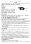
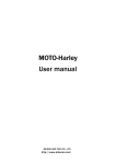
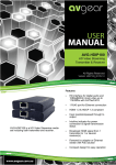
"KODINIS"
IMB5, IMB5.1
Vehicle immobilizer
Installation manual
LED hole
THE IMMOBILIZER PURPOSE
Button
Fig. 1. System unit.
Fig. 2. ID card.
The purpose of the immobilizer 'KODINIS' is
the identification of the driver. The driver is
identified, when the person with ID card comes
inside the communication area. If the person
has no ID card, the immobilizer regards the
vehicle is under unauthorized use and transfers
the signal for engine immobilization.
SAFETY WARNINGS
The immobilizer includes the system unit that must be installed inside the passenger compartment of the vehicle, and ID card
(2.4GHz RF key), that has the driver. The ID card and the system unit provide RF communication. There are two ID cards in the
set. It is possible to program up to 5 ID cards. The vehicle immobilizer manufacturer recommends the following:
1. Mount the immobilizer in place free from moisture and other elements that could pose to corrode the device. It should also be
placed as far away as possible from any heat emitting elements in the passenger compartment and sources of electromagnetic
interference (e.g., a vehicle computer, fans, relay blocks).
2. Avoid mounting the immobilizer directly onto metal parts of the vehicle to prevent the accumulation of condensation inside.
3. Mount the immobilizer so that the wire connectors are going from the bottom side of the immobilizer.
4. Avoid placing wires next to moving or hot parts of a vehicle.
5. Don't overload the immobilizer’s 1st optional control (Oc1) circuit 4 : the current should not exceed 0.3 A.
6. For EU countries only use settings compatible with EU Directives.
SPECIFICATIONS
1.
2.
3.
4.
5.
6.
Operating temperature range ..........................................................................
Supply voltage ................................................................................................
Average consumption current (except OC1) ................................................
Average control distance ................................................................................
Communication frequency range ...................................................................
Pulse radiated power ......................................................................................
- 40°C / +85°C.
9 - 15 V (nuolatinë átampa).
no more 10 mA (U = 12 V).
1 – 2 m.
2,4 GHz.
No more 1mW.
INSTALLATION SEQUENCE
1.
2.
3.
4.
5.
Select the purpose of the OC1 – Optional Control One (FN51).
Select the purpose of the input DOORS(-) (FN64).
Install the immobilizer in accordance with the wiring diagram, paying attention to the selected OC1 and DOORS(-) purpose.
Customize immobilizer if default settings are not suitable.
Fill out an installation certificate.
WIRING DIAGRAM
Immobilization circuit
with normally open (NO)
relay contacts (FN51, NN=4)
+12 V
Switches in the door strut,
input DOORS(-)
(FN64, NN=1)
OC1
87
85
30
86
3A
-
87a
+12 V
30
86
3A
Immobilization circuit
with normally closed (NC)
relay contacts (FN51, NN=1)
1-second pulse for external engine
immobilization device (FN51, NN=2)
OC1
Automatic engine start
module (FN64, NN=4)
Immobilizer status
(Fn51, NN=3)
OC1
Connection with alarm system
(FN51, NN=5)
OC1
Communication with ID card
status indication (FN51, NN=6)
OC1
87
85
Authorization button
(FN64, NN=2)
+12V
Ingition switch
ON
ACC
START
System LED
+12 V
Battery
+12V
5A
+
-
„Ground”
(Car’s body)
Buzzer
Black
Yellow
Blue
Grey
Brown
White
Red
Red
Black
1 2 3 4 5 6 7 1 2
OC1
87a
IMB5
"KODINIS"
IMB5, IMB5.1
Vehicle immobilizer
Installation manual
SYSTEM SETUP MODE
The 'IMB5' features up to 24 system settings. Due to these settings the 'IMB5' can be adjusted to a particular vehicle or
relevant customer’s requirements. The immobilizer is supplied with the factory preset default settings listed in the table. If the
default settings are not suitable for the user you can customize them. To customize the immobilizer do the following steps:
1. Enter the PIN code (see TURNING ON THE OVERRIDE MODE in User manual).
2. If it is necessary to program no ID card, wait for 3 seconds with ignition is turned OFF, untill the system LED will
finish tripple flashes and will start frequent flashes. You have 80 seconds (control time) to start entering the FN.
Sample 1 – the sequence of the FN21 setting checking up:
Double
flashes
ON
OFF
ON
Orange
Double
flashes OFF
8 min.
8 min.
FN digit '2'
is entered
FN dgit '1'
is entered
Press the button on Number of short buzzer
Short buzzer sound
shows, that right FN is the ID card, which sounds shows current SN
entered, the control time is is turned OFF
value, the control time
extended up to 8 minutes
is extended up to 8 minutes
Sample 2 – the sequence of the FN22 setting SN=2 entering, checking up and returning to operating mode:
Double
flashes
ON
OFF
ON
Double
flashes
Orange
ON
OFF
OFF
2-3
seconds
8 min.
FN digit '2'
is entered
8 min.
Short buzzer sound
shows, that right FN is
entered, the control time is
extended up to 8 minutes
FN digit '2'
is entered
Orange
ON
Double
flashes
O FF
ON
Press twice (SN=2)
the button on the
ID card, which
is turned OFF
Double
flashes
Long buzzer sound shows,
that right SN value is entered
successfully, the control time
is extended up to 8 minutes
Green
OFF
8 min.
Press the button
Number of short buzzer
on the ID card, sounds shows the new entered
which is
SN value, the control time
turned OFF
is extended up to 8 minutes
FN digit '1'
is entered
FN digit '1'
is entered
Rare system LED flashes shows ID card is turned
ON, immobilization
that the system is in normal
signal is turned OFF,
operating mode, the engine
system LED goes OFF
immobilization signal is ON
LEARNING THE ID CARDS
The user can learn to the system up to 5 ID cards. The all early learned ID cards are deleted from the system. It is
highly useful, if ID the card is theft or lost. The ID cards must be turned OFF during learning. Action sequence:
1. Enter the PIN code (see TURNING ON THE OVERRIDE MODE in User manual). The system LED will flash for 2
seconds by triple flashes. It is necessary to turn ON the ignition during this time.
Triple
flashes
2
seconds
ON
12 sec.
The control time is
extended up to 12 seconds
Orange
OFF
1 sec.
Trigubi
12 sec. blyksniai
Orange
1 sec.
12 sec.
The button on
The button on
1 second flash, the
1 second flash, the
the 1st ID card is pressed button is released, the the 2nd ID card is pressed button is released, the
and hold pressed down 2nd ID card is learned
and hold pressed down
1st ID card is learned
Triple
flashes
12
seconds
AVAILABLE IMMOBILIZER SETTINGS
In the column named "EU" the settings which comply with the requirements of EU Directives are indicated with a tick mark
. Selection of settings not complying with the EU requirements is allowed if the vehicle is operated outside the EU states.
In the column "IMB5" the settings which present with the immobilizer software version are indicated by a tick mark . The
factory default (pre-set) settings are indicated with the tick mark in the "IMB5" column.
FN=11 Function: EXIT OVERRIDE MODE.
FN=21 Function: IMMOBILIZATION SIGNAL.
The immobilization signal is turned ON when the 20 second time after the ignition is turned OFF is elapsed, if there is no programmed ID card signal in the
SN=1 communication area. The signal is turned OFF when appears programmed ID card signal and authorization button is pressed (depending on FN64 setting).
SN=2 Immobilization signal is turned OFF.
FN=22 Function: 'ANTI-CARJACK'.
SN=1 'Anti-carjack' is turned OFF.
'Anti-carjack' procedure is triggered by ignition turning ON with no programmed ID card inside communication area or by ID card signal loss with ingnition
is turned ON. The immobilizer waits for programmed ID card signal within 120 second override time and follows 'anti-carjack' operation settings (FN23). With the
SN=2 last 25 seconds the immobilizer warns by short buzzer signals with increasing frequency. In 10 seconds warning signal becomes continuous. 'Anti-carjack' operation
cancelling or trigger prevention is available at any time by programmed ID card signal inside communication area. If is selected (SN=2 for FN64) and
immobilization signal is turned OFF (SN=2 for FN21), the authorization button should be pressed every time when the ignition is turned ON.
IMB5
FUNCTION
EU
AVAILABLE SETTINGS
"KODINIS"
IMB5, IMB5.1
FUNCTION
SN=3
'Anti-carjack' procedure is triggered by ignition turning ON with no programmed ID card iside communication area. The immobilizer waits for programmed
ID card signal within 60 second override time and follows 'anti-carjack' operation settings (FN23). With the last 25 seconds the immobilizer warns by short buzzer
signals with increasing frequency. In 10 seconds warning signal becomes continuous. 'Anti-carjack' operation cancelling or trigger prevention is available at any time
by programmed ID card signal inside communication area. If is selected (SN=2 for FN64) and immobilization signal is turned OFF (SN=2 for FN21), the
authorization button should be pressed every time when the ignition is turned ON.
SN=4
'Anti-carjack' procedure is triggered by ignition turning ON with no programmed ID card inside communication area or by opening the door with ignition is
turned ON and the ID card signal loss afterwards. The immobilizer waits for programmed ID card signal within 60 second override time and follows 'anti-carjack'
operation settings (FN23). With the last 25 seconds the immobilizer warns by short buzzer signals with increasing frequency. In 10 seconds warning signal becomes
continuous. 'Anti-carjack' operation cancelling or trigger prevention is available at any time by programmed ID card signal inside communication area. If is
selected (SN=2 for FN64) and immobilization signal is turned OFF (SN=2 for FN21), the authorization button should be pressed every time when the
ignition is turned ON.
FN=23 Function: IMMOBILIZATION SIGNAL DURING 'ANTI-CARJACK' OPERATION.
With the last 15 override time seconds the buzzer signal becomes continuous, after 15 seconds the buzzer signal is turned OFF and immobilization signal is turned
SN=1 ON. The immobilization signal can be transfered to OC1 (SN=1, SN=4 for FN51), to alarm system (SN=5 for FN51) or to external immobilization equipment
(SN=2, SN=6 for FN51). For immobilization signal cancelling is necessary the turned ON programmed ID card inside communication area and the authorization
button press (depending on FN61, FN64 settings).
With the last 15 override time seconds the buzzer signal becomes continuous, you can turn OFF it only by turning OFF the ignition, but not earlier as the override
time elapses. The immobilization signal is turned ON only as the ignition is turned OFF, it can be transferred to OC1 (SN=1, SN=4 for FN51), to alarm system
(SN=5 for FN51) or external immobilization equipment (SN=2, SNF=6 for N51). For immobilization signal cancelling is necessary the turned ON programmed ID
card inside communication area and the authorization button press (depending on FN61, FN64 settings).
With the last 15 override time seconds the buzzer signal becomes continuous and the immobilizer starts to transfer „a soft” (gradual) immobilization signal to
OC1 (SN=1, SN=4 for FN51). When the override time elapses the buzzer signal is turned OFF and the immobilization signal is turned ON. The immobilization
SN=3 can be transferred to Oc1 (SN=1, SN=4 for FN51), to alarm system (SN=5 for FN51) or to external immobilization equipment (SN=2, SN=6 for Fn51). For
immobilization signal cancelling is necessary the turned ON programmed ID card inside communication area and the authorization button press (depending on
Fn61, FN64 settings).
FN=43 Function: ID CARD SIGNAL LOST WARNING.
SN=1 Warning is ON. When 20 second time elapses after the ID card signal is lost the immobilizer warns every 5 seconds within 3 minute time by buzzer sounds.
SN=2 Warning is OFF.
FN=45 Function: LOW ID CARD BATTERY WARNING.
SN=2
SN=1
SN=2
FN=51
SN=1
Warning is ON. When the ignition is turned ON the immobilizer warns by the series of 4 double buzzer signasl with interval of 1.7 second.
Warning is OFF.
Function: IMMOBILIZATION SIGAL.
SN=2
When the ignition is turned ON with immobilization signal ON, the negative polarity 1 second duration pulse, intended for an external immobilization equipment, is
transferred to OC1.
The immobilization signal is transferred to optional control 1. The OC1 is used for control a relay with normally closed contacts.
If the immobilization signal is ON, the negative polarity signal is transferred to OC1. If the immobilization signal is OFF on OC1 presents no signal.
The immobilization signal is transferred to optional control 1. The OC1 is used for control a relay with normally closed contacts.
Communication with an alarm system. Oc1 is intended wit alarm system listed in compatible system list.
The constant negative polarity signal is tranfered to OC1, if communication with ID card is OK. If the communication, fails the signal transfer is terminated with
5 second delay.
SN=7 The constant negative polarity signal is tranfered to OC1, if communication with ID card is OK. If the communication fails, the signal transfer is terminated with
0.7 second delay.
FN=61 Function: AUTHORIZTION BUTTON PRESS.
SN=1 Single press. The authorization button must be pressed 1 time within 5 sesecond time till ignition turning ON or arter ignition turning ON.
SN=2 Double press. The authorization buttton must be pressed 2 times within 5 sesecond time till ignition turning ON or arter ignition turning ON.
FN=64 Function: INPUT 'DOORS (–)' PURPOSE.
SN=1 Dooors (–).
SN=2 Authorization button (–).
SN=3 Not used.
AUTOSTART (–). When the input is connected to a low-level signal source (no more than +0.5 V) the immobilization signal is turned OFF. An automatic engine
SN=4 start module can to turn ON the ignition and starter. While the input is connected, PIN code entering is unavailable.
FN=81 Function: CHANGING THE PIN.
FN=91 Function: RESTORE FACTORY DEFAULT SETTINGS.
SN=1 Restore default factory settings and the default PIN code.
SN=3
SN=4
SN=5
SN=6
CERTIFICATE OF INSTALLATION.
I, undersigned qualified installer
certify that installation of
(Name, Surname)
the below described vehicle alarm system has been carried out by myself pursuant to installation manual supplied by the manufacturer of the system.
Vehicle description:
Manufacturer and model:
Serial number:
Registration number:
Description of vehicle immobilizer:
Type: 'IMB5'. Model:
Official approval number:
Installation date:
Installing company:
SEAL
Installer:
(Position, signature)
After installation of the alarm system installer must fill in CERTIFICATE OF INSTALLATION!
It is recommended to mark selected settings in the TABLE OF ALARM SYSTEM SETTINGS (underline SN).
IMB5
Installation manual
EU
Vehicle immobilizer