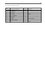
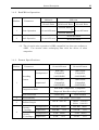
1
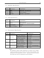
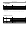
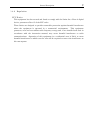
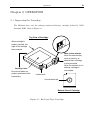
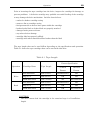
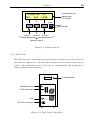
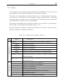
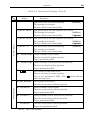
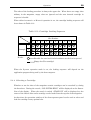
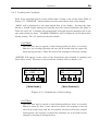
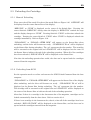
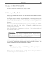
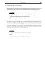
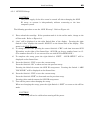
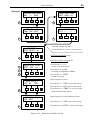
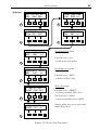
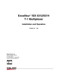
MS-8400 Series
MP-8400
Series
1 2 inch Cartridge Tape Subsystem
( with CSL model )
User Manual
KAT-M030-005
Thank You For Your Purchase.
To ensure correct operation, please read this USER MANUAL before using your
purchase. After reading this manual, store it in a safe place for future reference.
Revision : 5.21
3/30/2001
# All company names and brand names used in this manual are the registered
trademarks, trademarks and product names of the respective companies.
# The contents of this manual are subject to change without notice.
#
The contents of this manual may not be reproduced or quoted without the
express written permission of this company.
i
Table of Contents
Page
Accessory and Contents List
Chapter 1 GENERAL DESCRIPTION
1.1 Overview
ii
1
1.2 Features
1
1.3 Model Name
2
1.4 Specifications
3
Chapter 2 OPERATION
2.1 Inspecting the Cartridge
9
2.2 Operator Panel
11
2.3 Powering Up
20
2.4 Loading a Cartridge
27
2.5 Unloading the Cartridge
33
Chapter 3 MAINTENANCE
3.1 Cleaning the Tape Head
35
3.2 Repairing the Leader Block
36
Chapter 4 INSTALLATION and SETUP
4.1 Installation
37
4.2 Setup
39
4.3 Diagnostics
46
4.4 Hierarchic Structure of Setup
48
Chapter 5 TROUBLE SHOOTING
5.1 Error Display
5.2 Countermeasures
53
53
~56
ii
[ Accessory and Contents List ]
Accessory and Contents
Quantity
1
User Manual
1
2
Power Cable
1
3
SCSI Cable
4
SCSI Terminator
1
5
Clamp Filter
2
6
Cartridge
1
7
Cleaning Cartridge
1
8
Key
Comments
Option
(2)
for test purposes
Option
General Description
1
Chapter 1 GENERAL DESCRIPTION
1.1 Overview
The MS-8418 is a 18 track, 1/2 inch cartridge tape drive that is fully compatible with the
IBM 3480/3490.
The MS-843x is a 36 track drive fully compatible with the IBM 3490E.
Both drives are equipped with the industry standard SCSI interface, which enables
simple connection to computers. In addition, both drives support IDRC, the industry
standard for data compression. Average of 600MB of data can be stored onto a cartridge
with the MS-8418 and average of 2.4GB can be stored with the MS-843x using the
extended cartridge (332m tape).
This device is a Cartridge Stack Loader(CSL) that can store up to 10 cartridges for
continuous automatic loading.
1.2 Features
These tape drives have the following features (the features differ depending on the
specifications).
High-speed Backup
Continuous data transfers are possible at a speed of 3MB/sec., even without the use of
compression. Maximum burst transfer speed is 20MB/sec.
Large-volume Backup
An average of 24GB of data can be stored per 10 cartridges when IDRC compression is
used.
Compatibility
The drives are compatible with IBM 3480/90/90E, thus facilitating the exchange of data
with host computers.
Easy Connection
The SCSI-2/3 interface is used for easy connection to work stations, personal computers
and other types of computers.
Expandability
The drive firmware is stored in the flash ROM; to improve the functions, firmware
updates are also possible from tape. The 18-track specifications can be changed to 36track specifications and the SCSI-2 specifications can be changed to SCSI-3, etc.
2
General Description
10 cartridges Magazine
Up to 10 cartridges can be loaded into the removable magazine. Separate magazines
can be used for different applications and for portability.
1.3 Model Name
1.3.1 Model Names by Track Specification
Track Specifications
MS-8418
Tape Speed
Standard Speed
MS-843x
18 track Drive
18/36 track Drive
36 track Drive
MS-8418
MS-843E
MS-8436
1.3.2 Model Names by SCSI Specification
Model Name
MS-8418
MS-843x
SCSI Connector Specifications
LS
Low-density 50pin (Amphenol)
WS
Hi-density 68pin (Wide SCSI)
WD
Hi-density 68pin (Wide SCSI)
SCSI Electrical Specifications
Single-ended
Differential
1.3.3 Model Names by Door Specification
Model Name
Door Specification
MS-8418##-
DA
no door lock
MS-843x##-
DL
door lock included (with key)
Marks :
“##” as the model names by SCSI specification.
3
General Description
1.4 Specifications
1.4.1 Performance Specifications
Number
Parameter
MS-8418
MS-843x
2 m/s
Read / Write
(79 ips)
Tape Speed
4 m/s
Rewind
(157 ips)
1
Speed Variation
2
(Short Term)
100 ms
(Standard)
Rewind
200 ms
Load Time
(average)
45 sec
Unload Time (average)
35 sec
(SCSI asynchronous)
Burst Transfer Rate
(SCSI synchronous)
Data Transfer Rate
(tape head)
3 sec (from EOT)
18 track
(1)
Burst Transfer Rate
90 sec
45 sec
Interface
5
7%
Read / Write
Read / Write Head
4
(Long Term)
Access Time
Rewind Time (max.)
3
4%
36 track
Fast SCSI - 2
(A Cable)
SCSI - 3
(P Cable)
(Single-ended or Differential)
5 MB/s (Narrow:8 bit)
10 MB/s
(Wide:16 bit)
10 MB/s (Narrow:8 bit)
20 MB/s
(Wide:16 bit)
3 MB/s
6
Block Size (max.)
7
Data Buffer Size
2 MB
8
Cartridge Loader
10 cartridges in the Removal Magazine
(1)
256 kB
Equipped with one type of interface per your specification.
section 1.3.2.
Refer to
4
General Description
1.4.2 Read/Write Operation
Number
MS-8418
Parameter
MS-843x
18 track Drive
18/36 track Drive
36 track Drive
18-track Format
1
Write Operation
(2) 36-track Format
18-track Format
36-track Format
2
Read Operation
18-track Format
18-track Format
36-track Format
(2) The 18-track write operation is IBM compatible but does not conform to
ANSI.
Use caution when exchanging data with the drives of other
companies.
1.4.3 Format Specifications
Number
Parameter
Uncompressed
Recording
Format
Compressed
1
Compression Mode
Error Correction
2
Record Density
3
Medium Length
4
18-track Format
36-track Format
IBM 3480
IBM 3490E
Compatible
Compatible
(ANSI X3B5)
(ANSI X3B5)
IBM 3490
IBM 3490E
Compatible
Compatible
(ANSI X3B5)
(ANSI X3B5)
IBM IDRC Compaction Compatible
(Improved Data Recording Capability)
Cross Parity
1491 cpmm
165 m
(541 ft.)
Reed Solomon
(37871 bpi)
165 m
(541 ft.)
332 m
(1100 ft.)
Capacity :
Uncompressed
200 MB
(max.)
800 MB
(max.)
1 cartridge
Compressed
600 MB
(3:1)
2.4 GB
(3:1)
Capacity :
Uncompressed
2 GB
(max.)
8 GB
(max.)
10 cartridges
Compressed
6 GB
(3:1)
24 GB
(3:1)
5
General Description
1.4.4 Reliability Specifications
Number
Parameter
Specification
1
MTBF
30000 hours
(25% duty cycle)
2
MTTR
Under 30 minutes
3
Head Life
3000 hours
(Tape motion)
1.4.5 Power Specifications
Number
Parameter
Specification
100 to 120 V, AC
1
Voltage
2
Line Frequency
50/60 Hz
3
Power Consumption
110 W
220 to 240 V, AC
(Automatic ranging)
1.4.6 Environmental Specifications
Number
1
Parameter
Operating
2
Operating
3
Non-operating
4
Non-operating
Specification
Dry Bulb Temperature
10°C to 40°C
Temperature Gradient
10°C / hour
Wet Bulb Temperature
Max. 26°C
Relative Humidity
20% to 80%
Humidity Gradient
20% / hour
Dry Bulb Temperature
-10°C to 60°C
Temperature Gradient
10°C / hour
Relative Humidity
5% to 95%
Humidity Gradient
20% / hour
(non-condensing)
(non-condensing)
NOTE
The applicable proposed ANSI specification for half-inch tape cartridge
requires operation in the range of 16°C to 32°C, 20% relative humidity and a
maximum wet bulb temperature of 25.6°C. Operation of this device beyond
these limits may result in a degradation of media reliability.
General Description
1.4.7 Acoustical Noise
Number
Parameter
Specification
1
Power-on Idle
50 dB A (max.)
2
Operating
55 dB A
3
Load / Unload
70 dB A (max.)
(max.)
Machine Noise
Sound power level : less than 70 db (A) according to DIN45635 part 19 (EN27779).
Maschinengeräusche
Geräuschpegel : weniger als 70 db (A) entsprechend DIN45635 Teil 19 (EN27779).
1.4.8 Mechanical Specifications
Number
1
Parameter
Dimensions
Specification
Height
429 mm
(16.9 in.)
Width
227 mm
(8.9 in.)
Depth
649 mm
(25.6 in.)
2
Weight
29 kg
(64 lb.)
3
Shipping Weight
36 kg
(79 lb.)
6
General Description
7
1.4.9 Regulation
FCC Notice
This equipment has been tested and found to comply with the limits for a Class A digital
device, pursuant to Part 15 of the FCC rules.
These limits are designed to provide reasonable protection against harmful interference
when the equipment is operated in a commercial environment.
This equipment
generates, uses and can radiate radio frequency energy and, if not installed and used in
accordance with the instruction manual, may cause harmful interference to radio
communications. Operation of this equipment in a residential area is likely to cause
harmful interference in which case the user will be required to correct the interference at
his own expense.
General Description
[ Notes ]
8
9
Operation
Chapter 2 OPERATION
2.1 Inspecting the Cartridge
The MS-8400 drive uses the industry-standard 3480-tape cartridge defined by ANSI
Standard X3B5. Refer to Figure 2-1.
Top View of Cartridge
When cartridge is
properly inserted, this
edge of the cartridge
faces outward.
Cartridge Label
Ensure that labels are
properly positioned within
indentations.
Write protect selector
When the white dot(key
mark) is showing, as
depicted here, cartridge
is write protected.
When the white dot is not
showing, cartridge is
write enable.
Leader block
Circular Metal Hub
Bottom View of Cartridge
Figure 2-1 Half-inch Tape Cartridge
10
Operation
Prior to inserting the tape cartridge into the drive, inspect the cartridge for damage to
prevent problems. A defective cartridge may prohibit successful loading of the cartridge
or may damage the drive mechanism. Look for these defects:
• cracked or broken cartridge casing
• water or dirt on cartridge casing
• foreign material or obvious loose parts within the cartridge
• broken leader block or leader block not properly attached
• damaged write protect selector
• any other obvious damage
• cartridge label not properly affixed
• cartridge with other materials affixed rather than the label
The tape length that can be used differs depending on the specifications and operation.
Table 2-1 shows the tape cartridges that can be used with this drive.
Table 2-1 Tape Length
Format Specification
Operation
Write
Read
Cartridge Name
Tape Length
18-track
36-track
Format
Format
3480 (Standard)
165m (541ft.)
Recommended
OK
Long (x1.5)
246m (807ft.)
OK
OK
3490E (Extended)
332m (1100ft.)
NG
Recommended
3480 (Standard)
165m (541ft.)
Recommended
OK
Long (x1.5)
246m (807ft.)
OK
OK
3490E (Extended)
332m (1100ft.)
OK
Recommended
CAUTION
The drive cannot load the cartridge is the contained tape is of insufficient
length.
11
Operation
2.2 Operator Panel
2.2.1 Front View
The operator panel and power switch are located on the front panel. The operator panel
is equipped with a 16-digit:2-line display, 3 switches and 2 indicators. These are used to
operate the drive. Refer to Figure 2-2 and 2-3.
Operator Panel
Door-Lock
(Optional)
Door Knob
OFF
Front Door
ON
Power Switch
Figure 2-2 Front View of the Drive
12
Operation
16-character 2-Line
STAND BY 18
OFL Sel LOAD
Alphanumeric
LCD Display
COMP.
Indicator
ALERT
Switch-1
Switch-2
Switch-3
Operation Switch
Figure 2-3 Operator Panel
2.2.2 Rear View
The SCSI connectors, maintenance port and AC power connector are located on the rear
panel (Refer to Figure 2-4). The two SCSI connectors can be used for either input or
output.
The maintenance port is used only for troubleshooting and should not be
connected during normal operation.
Portable Handle
Maintenance Port
SCSI Connectors
Fuse
AC Power Connector
Figure 2-4 Rear View of the Drive
Operation
13
2.2.3 Display
The 16-character 2-line alphanumeric LCD display with backlight on the front operator
panel displays various messages regarding drive operation and status.
The upper row of the display is called the “Status-Line”. It displays status information,
error codes, etc.. The lower row of the display is called the “Switch-Line”. Operation
switch functions are displayed here. Furthermore, the combination of the Status-Line
and Switch-Line is referred to as the “Menu-Display”.
The message of the display using both upper and lower row is called the “2-Line-Message”.
This message is only displayed temporarily (approx. 3 sec.).
Various “Status-Line” displays are explained in Table 2-2, 2-3 and 2-4. Various “2-LineMessage” displays are explained in Table 2-5.
Table 2-2 “Status-Line” Display (Part 1)
Display
Description
The drive is powering up and running the diagnostics.
ENABLE
The drive is loading.
Drive Status
LOADING
REWINDING
The drive is rewinding.
UNLOADING
The drive is unloading.
CLEAN
The drive requires cleaning with a cleaning cartridge.
CLEANING
The drive is being cleaned with the cleaning cartridge.
POWER-ON UNLOAD
After again turning on the power, the drive is unloading the
inserted cartridge.
PwrOn UNLD TO 10
After again turning on the power, the CSL return the inserted
CSL Status
cartridge to slot 10.
LOADING FROM #
The CSL is loading from the magazine.
UNLOADING TO #
The CSL is unloading to the magazine.
CSL INITIALIZING
The CSL is in operation.
WAITING CSL RDY
The CSL is in operation.
END OF STACK
The front door is open.
DOOR OPEN
REMOVE CART
All cartridges have been processed and unloaded.
#
Remove the cartridge from the magazine.
Marks : “# ” as slot number.
14
Operation
Table 2-3 “Status-Line” Display (Part 2)
Display
Description
STAND BY 18
This drive is only for 18-track cartridge.
[ MS-8418 ]
The cartridge is not loaded.
The drive will be ready after loading.
STAND BY 18w/36
This drive is set to the write operation for 18-track.
The cartridge is not loaded.
The drive will be ready after loading.
On-line Status
STAND BY 18/36w
STAND BY 36
[ MS-843x ]
< Option >
This drive is set to the write operation for 36-track.
The cartridge is not loaded.
The drive will be ready after loading.
[ MS-843x ]
< Option >
This drive is only for 36-track cartridge.
[ MS-843x ]
The cartridge is not loaded.
The drive will be ready after loading.
BOT ONLINE WE#
Loaded cartridge is write enable.
The drive is ready for on-line operation.
Tape is positioned at BOT.
BOT ONLINE FP#
Loaded cartridge is write protected (file protected).
The drive is ready for on-line operation.
Tape is positioned at BOT.
BOT
EOT
The cartridge is loaded and in use.
The drive is ready for on-line operation.
Tape is not positioned at BOT.
The “
” mark indicates
amount of tape used.
OFFLINE UNLOADED
The cartridge is not loaded.
Off-line Status
The drive is not-ready for off-line operation.
BOT OFFLINE WE
Loaded cartridge is write enable.
The drive is not ready for off-line operation.
Tape is positioned at BOT.
BOT OFFLINE FP
Loaded cartridge is write protected (file protected).
The drive is not ready for off-line operation.
Tape is positioned at BOT.
OFFLINE WE
The drive is not ready for off-line operation.
Tape is not positioned at BOT.
Marks : “# ” as slot number.
15
Operation
Table 2-4 “Status-Line” Display (Part 3)
Status
Off-line
Display
Description
ONL AFTER REWIND
The drive will be ready when
complete.
UNLOAD AFTER REW
SCSI ID
5
MENU FUNCTIONS
CONFIGURE
Setup Mode
The drive is rewinding.
DIAGNOSTICS
STATISTICS
ENTER PASSWORD
SAVE SETUP ?
ARE YOU SURE ?
The drive is unloading.
“SCSI ID” Setup menu. (for example; SCSI ID=5)
Setup mode. (Menu functions)
Configuration menu.
Diagnostics menu.
Statistics menu.
Request for password entry.
Input request to save in this menu.
Input request to confirm in this menu.
Error
Refer to items of each menu for details on the setup mode.
WRT PROTECT 1018
Cannot write to write protected cartridge.
18Thin Tape 1026
18-track format cannot write to extended cartridges.
NO MAGAZINE
NO CARTRIDGE
No magazine in the CSL.
No cartridge in the inserted magazine.
INVALID PASSWORD
Entered password is invalid.
DIAGNOSTIC ERROR
Error detected during powering up diagnostics.
Refer to Chapter 5 for details on errors with the lighted ALERT indicator.
Operation
Table 2-5 “2-Line-Message” Display
Display
DIAGNOSTICS
COMPLETED OK
Setup Mode
WILL SAVE SETUP
IN FLASH ROM
Description
Powering up diagnostics have successfully completed.
Can save to Flash-ROM.
SETUP SAVED
IN FLASH ROM
Saved to Flash-ROM.
NO CHANGES
TO CONFIG SETUP
Cannot change setup.
WILL SAVE SETUP
UNTIL POWER DOWN
Settings can be used until turning off power.
SETUP SAVED
UNTIL POWER DOWN
Settings stored until turning off power.
MUST POWER DOWN
BEFORE EFFECTIVE
Turn off the power.
DON'T POWER DOWN
Do not turn off the power.
16
17
Operation
2.2.4 Operation Switch
The 3 button type switches on the front operator panel are used to control the drive.
Operation switch function are displayed on the lower row (Switch-Line) of the display.
Follow the display to operate the 3 switches.
Pressing a switch changes the display contents of the menu. The Switch-Line will then
display new switch functions according to the new menu.
In other words, switch
functions change every time a switch is pressed. Relationship of the position between the
Switch-Line and the switches are explained in Figure 2-5. The function of the switches
are explained in Table 2-6.
“Status-Line” Display
“Switch-Line” Display
BOT
OFL
ONLINE WE 1
COMP --COMP.
ALERT
[Example-1]
“OFL” Switch Function
Switch-1
“COMP” Switch Function
Switch-2
“---“ Switch Function
Switch-3
Operation Switches
[Example-2]
BOT OFFLINE WE
ONL UNLD func
Switch-1 : “ONL”
COMP.
Switch-2 : “UNLD”
Switch-3 : “func”
Figure 2-5 Relationship of “Switch-Line” Positions
ALERT
Operation
NOTE
The display of each function is punctuated with 1 or more blank spaces.
Table 2-6 “Switch-Line” Display and Switch Function
Display
Switch Function
---
The switch is not defined.
>>>
Change to the next menu.
EXIT
Exit menu of the current layer.
YES
Permit input request of the Status-Line.
NO
Decline input request of the Status-Line.
TEMP
Temporarily use input request of the Status-Line.
OFL
Enter the off-line operation.
Sel
Select the magazine slot number.
LOAD
Load a cartridge into the slot having the selected number.
COMP
Switch the data compression mode.
ONL
Return to the on-line operation.
REW/UNL
Rewind.
UNLD
Unload.
DEN
The write operation can be switched for 18/36 track drive.
func
The “SCSI ID” setup.
func
The setup mode.
CHG
Change the “SCSI ID”.
EXIT
Return to the on-line operation.
CONF
The configure mode.
DIAG
The diagnostics mode.
STAT
The statistics mode.
Setup
FUNLD
Recover from servo error.
Mode
CSL
The CSL operation mode.
CHG
Change setup.
NEXT
Advance to the next display.
Common
On-line
Off-line
“SCSI ID”
Setup
Refer to items of each menu for details on the setup mode.
18
Operation
19
2.2.5 Indicator
The 2 indicators on the front operator panel show the drive status. The conditions for the
indicators lighting are explained in Table 2-7.
Table 2-7 Indicators
Indicator
Color
Description
When the LED is lighted, the drive writes in the compressed
mode(IDRC). When the LED is not lighted, the drive writes in the
COMP.
Green
uncompressed mode.
This LED indicates the writing mode and does not reflect the read
mode.
ALERT
Red
This LED is lighted when an error is detected. At this time, error
code etc. will be displayed on the Status-Line (upper row).
20
Operation
2.3 Powering Up
2.3.1 Installing Cables and Interfaces
Connect the attached AC power cable to the AC power connector located on the rear panel,
then insert the plug to an AC power outlet.
Refer to section 4.1 and connect the SCSI cable to the SCSI connector.
2.3.2 Turning in the Power
Turn the power switch on the front panel from off [ O ] to on [| ] (Refer to Figure 2-2) to
supply AC power to the drive. The backlight of the operator panel display will light
(yellow).
Self-diagnostics will be executed for approximately 20 seconds after turning the drive on.
During this time, “ENABLE...” will be displayed on the Status-Line of the display and
communication with interface and operator panel operations are disabled.
“STAND BY” is displayed on the Status-Line of the display when the self-diagnostics is
successfully complete and use of the drive is enabled.
If an error has been detected
during the self-diagnostics, the ALERT indicator will light and an error message will
appear on the display.
CAUTION
When turning off the power, wait at least 10 seconds before turning the
power back on.
2.3.3 On-line Mode / Off-line Mode
There are 2 types of operating modes: the on-line mode and off-line mode. The on-line
mode displays an on-line status on the Status-Line, indicating that the drive is ready.
The off-line mode displays an off-line status on the Status-Line, indicating that the drive
is not ready. Refer to Table 2-3.
The operation mode (on-line / off-line) can be switched using the operation switch on the
front panel. Figure 2-6 shows the procedure to switch from the on-line mode to the offline mode. Figure 2-7 shows the procedure to switch from the off-line mode to the on-line
mode.
21
Operation
[Example-1]
STAND BY 18
OFL Sel LOAD
OFFLINE UNLOADED
ONL --- func
1
1
2
Press Switch-1 ”OFL” to enter the Off-line mode.
[Example-2]
BOT
OFL
ONLINE WE 1
COMP ---
BOT OFFLINE WE
ONL UNLD func
1
1
2
Press Switch-1 ”OFL” to enter the Off-line mode.
Figure 2-6 On-line Mode to Off-line Mode
[Example-1]
OFFLINE UNLOADED
ONL --- func
STAND BY 36
OFL Sel LOAD
1
1
2
Press Switch-1 ”ONL” to enter the On-line mode.
[Example-2]
BOT OFFLINE WE
ONL UNLD func
BOT
OFL
1
1
2
Press Switch-1 ”ONL” to enter the On-line mode.
Figure 2-7 Off-line Mode to On-line Mode
ONLINE WE 7
COMP ---
22
Operation
During the on-line mode, tapes can be read/write when a cartridge is loaded. During the
on-line mode, a cartridge can be load from the magazine when a cartridge is not loaded.
The off-line mode enables unload and drive setup.
2.3.4 Switching the Recording Format
When the operation mode is in the on-line mode and when a cartridge is loaded, recording
format can be switched to uncompressed or compressed. Switching of recording format is
valid only tape positioned at BOT with write enable status and switching is automatic
when reading data. The COMP indicator also shows the recording format during writing
of data.
When the COMP indicator is lit, the drive will write in compressed format. Pressing the
center Switch-2 “COMP” will turn off the indicator and the drive will write in
uncompressed format. Refer to the left side of Figure 2-8.
When the COMP indicator is not lit, the drive will write in uncompressed format.
Pressing the center Switch-2 “COMP” will turn on the indicator and the drive will write in
compressed format. Refer to the right side of Figure 2-8.
[ Compressed Recording Format ]
BOT
OFL
ONLINE WE 2
COMP --2
[ Uncompressed Recording Format ]
BOT
OFL
ONLINE WE 2
COMP --2
Press Switch-2 ”COMP” to switch between uncompressed and compressed.
Figure 2-8 Switching the Recording Format
23
Operation
2.3.5 Switching the Write Operation [for 18/36 track drive only]
With 18/36 track drive, it is possible to switch between the 18-track and 36-track write
operation using the operation switches on the front of the operator panel.
The current write operation can be determined when “STAND BY” is displayed on the
center of the Status-Line. When “18/36w” is displayed on the right of the Status-Line,
the 36-track write operation is selected. When “18w/36” is displayed on the right of the
Status-Line, the 18-track write operation is selected.
In other words, the letter “w”
following the number of tracks indicates which operation is selected. Refer to Figure 2-9.
STAND BY 18/36w
OFL Sel LOAD
STAND BY 18w/36
OFL Sel LOAD
[ 36-track Write Operation ]
[ 18-track Write Operation ]
Figure 2-9 Current Write Operation
CAUTION
The 18-track write operation of the 18/36 track drive is IBM compatible but
does not conform to ANSI. Use caution when exchanging data with the
drives of other companies.
24
Operation
The following procedure to change the “Write Operation Setup”. Refer to Figure 2-10.
1)
First, unload the cartridge. If the operation mode is in the on-line mode, change to the
off-line mode. Refer to Figure 2-6.
2)
“DEN” will be displayed on the center Switch-Line of the display. Pressing the center
Switch-2 “DEN” displays the current write operation on the Status-Line of the display.
This menu is the Write Operation setup.
3)
To change the Write Operation, pressing the center Switch-2 “CHG” each time displays
another Write Operation on the Status-Line.
When “WRITE 18” is displayed on the center of the Status-Line, the 18-track write
operation is selected. When “WRITE 36” is displayed on the center of the Status-Line,
the 36-track write operation is selected.
When “TRACK” is displayed on the right of the Status-Line, the SCSI command is
enabled the write operation to change. When “(FORCE)” is displayed on the right of
the Status-Line, the SCSI command is disabled the write operation to change.
4)
To complete the setup, press the left Switch-1 “EXIT”.
displayed on the Status-Line.
5)
Press the Switch-1 “YES” to save the current setup.
“SAVE SETUP?” will be
Press the Switch-2 “NO” to abort and use the previous setup.
Press the Switch-3 “TEMP” to use the current setup until turning off the power.
Pressing the Switch-2 returns this menu. Pressing the Switch-1 or Switch-3 “ARE
YOU SURE ?” will be displayed on the Status-Line.
6)
Press the Switch-1 “YES” to save the current setup.
Press the Switch-2 “EXIT” to abort and use the previous setup.
Pressing either switch, this menu will be exited and the off-line mode will return.
25
Operation
[ Changing to 18-track Write Operation ]
[ Changing to 36-track Write Operation ]
STAND BY 18/36w
OFL Sel LOAD
STAND BY 18w/36
OFL Sel LOAD
1
1
1
1
OFFLINE UNLOADED
ONL DEN func
OFFLINE UNLOADED
ONL DEN func
2
2
2
2
WRITE 36 TRACK
EXIT CHG ---
WRITE 18 TRACK
EXIT CHG ---
2
2
3
3
WRITE 18 TRACK
EXIT CHG ---
WRITE 36 TRACK
EXIT CHG ---
1
1
4
4
SAVE SETUP ?
YES NO
TEMP
Input request for save.
Press Switch-1 “YES” to save the setup.
Press Switch-2 “NO” to abort the setup.
1
2
3
5
until turning off the power.
ARE YOU SURE ?
YES EXIT --1
6
Press Switch-3 “TEMP” to use the setup
2
Input request for confirmation of save.
Press Switch-1 “YES” to save the setup.
Press Switch-2 “EXIT” to abort the setup.
Figure 2-10 Write Operation Setup
26
Operation
2.3.6 CSL Operation Mode
The method used by the Cartridge Stack Loader(CSL) to load and unload cartridges
differs depending on the operation mode.
overviews.
Table 2-8 shows the operation modes and
Table 2-9 explains the loading methods.
Refer to section 4.2.3 for the
operation mode setting method.
Table 2-8 CSL Operation Mode
Mode
Display
Manual
Manual
Description
The cartridges must be loaded one at a time.
After the first cartridge has been loaded and then unloaded
with the SCSI Unload command from the host computer, the
Auto
next cartridge will be loaded automatically. A maximum of 10
cartridges can be loaded continuously and automatically in this
Automatic
way.
AUTOcyc
SYS
System
Operation is the same as for [Auto] but, when the last cartridge
has been unloaded, the first cartridge will again be loaded.
SCSI cartridge loader commands are supported.
SYSauto
Random
Operation is the same as for [SYS] but automatic loading is
possible.
SCSI media changer device commands are supported.
Table 2-9 CSL Loading Methods
Operation
First Cartridge
Mode
Manual
Automatic
Next Cartridge
Load
Unload
Load
Unload
LOAD
UNLD
LOAD
UNLD
SCSI Load
SCSI Unload
SCSI Load
SCSI Unload
LOAD
UNLD
LOAD
UNLD
SCSI Load
SCSI Load
SCSI Unload
System
Marks :
Auto Load
SCSI Unload
Any cartridge can be loaded and unloaded.
LOAD
UNLD
“SCSI Load” / “SCSI Unload”
Manual operation using the Operator Panel.
Remote control from SCSI.
27
Operation
2.4 Loading a Cartridge
Before loading a cartridge, make sure that the write protect selector is on either write
enable (white dot not showing) or write protected (white dot showing). Refer to Figure 2-1.
NOTE
The write protect selector on the cartridge protects data from being
overwritten. When the write protect selector is on the write protect position,
the white dot (key mark) on the flat side of the selector will be visible from
the side of the cartridge.
2.4.1 Front Door
It is possible to lock/unlock the front door by using the supplied keys (door-lock and keys
are optional). To lock the front door, insert the key in the door-lock keyhole located on the
front panel and turn counterclockwise. To unlock the front door, insert the key in the
door-lock keyhole located on the front panel and turn clockwise. Refer to Figure 2-11.
The front door can be opened by pulling the door knob when unlocked. “DOOR OPEN”
will be displayed on the Status-Line when the front door is open. To close the front door,
push it back to the original position.
NOTE
The front door can be opened or closed regardless whether the power is on.
The CSL mechanism will automatically stop operation if the door is opened.
The CSL mechanism will resume operation when the door is once again
closed, however, operation may take some time since cartridges will be rescanned.
Key
Keyhole
Key
[ Unlock ]
[ Lock ]
Figure 2-11 Door Lock
28
Operation
2.4.2 Magazine
Up to 10 cartridges can be loaded into the magazine provided with the CSL.
This
magazine can be removed by opening the front door and can be carried using the
magazine handle.
To remove the magazine from CSL: Open the front door and grasp the magazine handle.
Tilt the upper section of the magazine forward and pull up.
To install the magazine into the CSL:
Open the front door and while grasping the
magazine handle, let the bottom of the magazine rest on the bottom holder. Push the
upper section of the magazine until it locks in position. Refer to Figure 2-12.
Magazine Handle
Front Door
Magazine
Door Knob
Zoomed View
Magazine
Bottom Holder
Bottom Holder
Figure 2-12 Installing the Magazine
CAUTION
When transporting the magazine, carry by the magazine handle so that the
bottom of the magazine becomes directly under. Shaking the magazine may
cause cartridges to fall from the slots.
29
Operation
2.4.3 Inserting a Cartridge
Each of the magazine's 10 cartridge slot can hold one cartridge and is numbered 1
through 10, top to bottom. Each slot is the same and cartridges are only distinguished by
their number. Refer to Figure 2-13.
Open the front door and insert the cartridges facing in the correct direction (leading block
away from you) into the slot of the magazine, as shown in Figure 2-13. Insert cartridge
completely until hitting the stopper located on the left side of the slot.
Slot Number
Slot-1
Slot-2
Slot-3
Slot-4
Slot-5
Slot-6
Slot-7
Slot-8
Slot-9
Slot-10
Leader Block
Cartridge
Figure 2-13 Inserting a Cartridge
NOTE
Cartridges can be inserted into magazines while removed from the CSL.
Follow the same procedure as when within the CSL. Refer to Figure 2-13.
30
Operation
The order of the loading procedure is always the upper slot. When there are empty slots
midway in the magazine, empty slots are ignored and the next inserted cartridge in
sequence is loaded.
When either Automatic or Manual operation is set, the cartridge loading sequence will
be as shown in Table 2-10.
Table 2-10 Cartridge Loading Sequence
Slot Number
Example
1
2
3
4
5
6
7
8
9
10
1
1
2
3
4
5
6
7
8
9
10
2
1
2
3
4
5
3
Marks :
1
2
6
3
4
5
Possible for auto load (circled numbers are the load sequence).
Empty slot (No cartridge).
When the System operation mode is set, the loading sequence will depend on the
application program being used by the host computer.
2.4.4 Selecting a Cartridge
Whether or not the slots of the magazine contain cartridges can be searched by closing
the front door. During the search, “CSL INITIALIZING” will be displayed on the StatusLine of the display. When the search is ended, “STAND BY” will be displayed on the
center of the Status-Line and a cartridge can be loaded into the top slot of the magazine.
At that time, the operation switches of the front operator panel can be used to select and
load the cartridge in any optional slot.
31
Operation
The following procedure to select the “Slot
STAND BY 18/36w
OFL Sel LOAD
Number Select setup”. Refer to Figure 2-14.
1)
2)
3)
4)
First, unload the cartridges. If the operation
mode is in the off-line mode, change to the online mode. Refer to Figure 2-7.
“Sel” will be displayed on the center SwitchLine of the display.
Pressing the center
Switch-2 “Sel” displays the currently selected
slot number on the Status-Line of the display.
This menu is the Slot Number Select setup.
To change the Slot Number, pressing the
center Switch-2 “NEXT” each time increases
slot number on the right of the Status-Line.
Only the numbers of slots where cartridges are
inserted will be displayed.
Press the Switch-1 “SAVE” to select the
currently displayed slot number.
1
2
2
SELECT CART
1
SAVE NEXT EXIT
2
3
SELECT CART
5
SAVE NEXT EXIT
1
Press the Switch-3 “EXIT”, operation will end
without changing the slot number.
5)
3
4
SELECT CART
5
SAVE NEXT EXIT
Pressing the Switch-3 “EXIT”, this menu will
be exited and the on-line mode will return.
3
5
Figure 2-14 Slot Number Select
CAUTION
When the Slot Number Select setup is exited, cartridges below the selected
slot number can be used. Consequently, cartridges above the selected slot
number will be ignored. To use cartridges above the selected slot number,
repeat the operation using the Slot Number Select setup.
32
Operation
2.4.5 Loading the Cartridge
First, if the operation mode is in the off-line mode, change to the on-line mode (Refer to
Figure 2-7). “STAND BY” will be displayed on the center Status-Line of the display.
“LOAD” will be displayed on the right Switch-Line of the display. Pressing the right
Switch-3 “LOAD” begins loading the cartridge from the selected magazine slot (Refer to
Table 2-9 and 2-10). Cartridge will automatically be loaded from the magazine slot to the
tape path within the drive. “LOADING FROM xx” will be displayed on the Status-Line
during loading. The “xx” represents the slot number.
CAUTION
The front door may be opened or closed during while the device is on ready.
However, the cartridge following the one will be loaded from the upper slot
when opening the door. Thus, the order of the cartridge to load may change.
“ONLINE” will appear on the center of the Status-Line when loading is complete and
drive will be ready. The drive is now read/write enabled. Refer to Figure 2-15.
BOT
OFL
ONLINE WE 5
COMP ---
[ Write Enable ]
BOT
OFL
ONLINE FP 5
-----
[ Write Protected ]
Figure 2-15 Completion of the Loading
CAUTION
The front door may be opened or closed during while the device is on ready.
However, when the door is once opened or closed, the cartridge in the top
slot will be loaded next and the slot number selection will become invalid.
Consequently, the sequence in which the cartridges are to be loaded can be
changed by opening or closing the door.
Operation
33
2.5 Unloading the Cartridge
2.5.1 Manual Unloading
First, enter the off-line mode if in the on-line mode (Refer to Figure 2-6). “OFFLINE” will
be displayed on the center Status-Line of the display.
“REW/UNL” or “UNLD” is displayed on the center of the Switch-Line. Pressing the
center Switch-2 “REW/UNL” during when the display is “REW/UNL” rewinds the tape
and the display changes to “UNLD”. Pressing Switch-2 “UNLD” at this time unloads the
cartridge. Pressing the center Switch-2 “UNLD” when “UNLD” is displayed unloads the
cartridge immediately. Refer to Figure 2-16.
“UNLOADING” or “UNLOAD AFTER REW” will appear on the Status-Line when
unloading, and the drive will become not ready. “UNLOADING TO xx” will be displayed
on the Status-Line during unloading. The “xx” represents the slot number. The cartridge
will be returned to the original slot and “STAND BY” will be displayed on the center of
the Status-Line to indicate the end of the unloading operation. When all of the cartridges
have been unloaded, “END OF STACK” will be displayed on the Status-Line.
Now that the unloading operation has ended, the door can be opened and the cartridges
removed from the magazine.
2.5.2 Unloading from SCSI
Set the operation mode to on-line and execute the SCSI Unload Command from the host
computer.
“UNLOADING” or “UNLOAD AFTER REW” will appear on the Status-Line of the display
when unloading, and the drive will become not ready. “UNLOADING TO xx” will be
displayed on the Status-Line during unloading. The “xx” represents the slot number.
The cartridge will be returned to the original slot and “STAND BY” will be displayed on
the center of the Status-Line to indicate the end of the unloading operation.
After that, if there is a cartridge in the lowermost slot of the magazine, cartridges can be
loaded automatically from the slots above. Refer to section 2.3.6.
If there is no cartridge in the lowermost slot, that is, when all of the cartridges have been
unloaded, “END OF STACK” will be displayed on the Status-Line, and the door can be
opened and the cartridges removed from the magazine.
34
Operation
[Example-1]
BOT
OFL
---
EOT
---
1
OFFLINE WE
ONL REW/UNL func
2
2
1
Press Switch-1 ”OFL”
Press Switch-2 ”REW”
to enter the off-line mode.
to rewind the cartridge.
REWINDING
ONL UNLD ---
END OF STACK
OFL Sel LOAD
2
4
3
Press Switch-2 ”UNLD”
to unload the cartridge.
[Example-2]
BOT
OFL
ONLINE FP 1
-----
BOT OFFLINE FP
ONL UNLD func
1
2
2
1
Press Switch-1 ”OFL”
Press Switch-2 ”UNLD”
to enter the off-line mode.
to unload the cartridge.
Figure 2-16 Unloading the Cartridge
CAUTION
If the drive is to be relocated or reshipped, unload and remove the cartridge
first. Furthermore remove all cartridges from the magazine. If a drive is
transported with the cartridge still inserted, the media could be damaged,
resulting in loss data.
35
Maintenance
Chapter 3 MAINTENANCE
This drive is designed for maintenance free, except as follows.
3.1 Cleaning the Tape Head
Clean the tape head and path using the IBM 3480 cleaning cartridge (IBM P/N 4780527
or compatible).
This cleaning operation should be performed periodically to help prevent read or write
errors.
The tape head and path should be cleaned every 8 hours during continuous
operation.
They should be cleaned at least once a day, even if the operation is not
continuous.
Clean the tape head and path immediately if the operator panel display the “CLEAN”
message on the Status-Line of the display.
This message is displayed only when
rewinding, loading or unloading.
Follow the manufacturer’s recommendations for the use of the cleaning cartridge and
keep track of the number of uses.
WARNING!
Do not clean the tape head directly with cotton swabs etc.. The tape head of
the drive may be destroyed due to its thin coating structure, if the receiving
force exceeds the pressure of prescription (tape tension).
Load the cleaning cartridge into the drive as with standard cartridges (Refer to Section
2.4).
The drive automatically initiates cleaning when the cartridge is loaded.
The
cartridge is automatically unloaded when cleaning is complete.
NOTE
When cleaning is complete, the “CLEAN” display will be replaced by the
standard Status-Line display.
Marking the top face label of a cleaning cartridge whenever cleaning has finished is
convenient to keep track of the number of uses.
Maintenance
36
3.2 Repairing the Leader Block
Although not often, the leader block may sometimes separate from the tape. If this occurs,
reattaching the leader block to recover previously recorded data is permitted one time.
CAUTION
The following procedure is only permitted when the cartridge contains
important data that needs to be recovered. The leader block attachment is a
temporary part permitted to recover data one time.
After reattaching the leader block and transferring the contained important
data to a computer, destroy the cartridge.
The leader block of the cartridge can be reattached easily by using the leader block
attachment kit (IBM P/N 4780625). This kit contains a leader block, leader block pin and
clutch tool. To reattach leader block, remove tape from the cartridge then attach the
leader block to the tape in a straight line. The leader block insert kit (IBM P/N 4780624)
containing only a leader block and leader pin is also available. For procedure on the
repair, refer to the instructions enclosed with either kit.
CAUTION
Always use the clutch tool to replace the leader block.
NOTE
For repair kits, contact the cartridge manufacturer.
Install and Setup
37
Chapter 4 INSTALL and SETUP
4.1 Installation
4.1.1 Installation Procedure
Use the following procedure to install this drive. For details, refer to the “Installation
Notes” of the host computer.
1)
Install the drive in a safe place. Do not connect the SCSI cables yet.
2)
Operate the host computer and search for a vacant SCSI ID number.
3)
Stop the host computer system and turn off the power supply.
4)
Connect the AC power cable and SCSI terminator to the drive. (Refer to section 4.1.3.)
5)
Turn on the drive power supply. (Refer to section 2.3.2.)
6)
Set the drive SCSI ID to the vacant number, and set the emulation mode, etc., to match
those of the host computer system. (Refer to section 4.2.)
7)
Turn off the drive power supply. (Refer to section 2.3.2.)
8)
Connect the host computer system and the drive. (Refer to section 4.1.3.)
9)
Turn on the drive power supply and then start the host computer system.
10) Operate the host computer and register the drive.
4.1.2 Installation Precautions
Observe the following precautions during installation.
1)
The host computer system should be operated by the systems manager.
2)
The SCSI cable should be the minimum possible length. Also, use high-impedance
shielded cable.
3)
Always install a SCSI terminator at both ends of the SCSI system being connected.
Also, use an active SCSI terminator (ALT-2) for single-end SCSI model.
4)
Do not turn off the drive power supply while the host computer system is in use.
5)
After turning off the drive power supply, wait at least 10 seconds before turning the
power supply on again.
38
Install and Setup
4.1.3 SCSI Cable Connection
The two SCSI connectors on the rear panel of the drive can be used for either input or
output. Refer to Figure 4-1 and connect the SCSI cables and the SCSI terminator. Also
install a clamp filter on the SCSI cable and fasten it at the end near the SCSI connector
of the drive.
Host Computer System
Magnetic Tape Drive
SCSI Initiator
(Relay SCSI device)
(Internal SCSI Terminator)
Magnetic Tape Drive
(End of SCSI device)
SCSI
SCSI Cable
SCSI Cable
Terminator
(ALT-2)
Clamp Filter
Clamp Filter Installation
Fastening the Clamp Filter
claws
Plug into the
Tighten until
SCSI connector
the claws are
end and fasten
completely
with the band
locked.
provided.
Pull strongly
Install the cable.
Figure 4-1 SCSI Cable Connection
Cut unnecessary
parts.
39
Install and Setup
4.2 Setup
This drive can be set up from the operator panel on the front.
Table 4-1 shows the standard setup values. Also, when changing the standard setup
values, enter the changes in this table for reference. (Refer to section 4.4 for the values
that can be set.)
Table 4-1 Setup Values
Contents
Type
SCSI
Items
Standard Setup Value
Currently
MS-8418
Set Value
SCSI ID
5
CSL LUN
WIDE NEGT
1
SCSI-2 model : DSABL
SCSI-3 model : ENABL
SYNC NEGT
ENABL
SAVE PNTR
ENABL
LD/RWD STAT
OFLN
BUFER MODE
buff
FMK SYNC
all
BOT PRE-RD
norm
WR RETRIES
10
RD RETRIES
10
COMPRESSION
OFF
ON
EMULATION
ECHO
DEFALT CFG
FLASH
WRT ERR
norm rec
PERM RD ERR
ERSE W2 DID
norm
---
Rd AHEAD FMK
18WRT
CSL
WRITE
norm
go
---
CSL MODE
UCODE
CURRENT SCSI
CURRENT SERVO
CURRENT CSL
18/36 track model.
36 TRACK
Auto
CURRENT CNTL
CURRENT FORM
Comments
ON
COMP SWITCH
DRIVE
MS-843x
MEC
Enter when the firmware
is updated.
MEF
MES
MEV
MEL
40
Install and Setup
4.2.1 SCSI ID Setup
CAUTION
The power supply of the drive must be turned off when changing the SCSI
ID setup, so operate it independently without connecting to the host
computer system.
The following procedure to set the “SCSI ID setup”. Refer to Figure 4-2.
1)
First, unload the cartridge. If the operation mode is in the on-line mode, change to the
off-line mode. Refer to Figure 2-6.
2)
“func” will be displayed on the right Switch-Line of the display. Pressing the right
Switch-3 “func” displays the current “SCSI ID” on the Status-Line of the display. This
menu is the SCSI ID setup.
3)
To change the SCSI ID, pressing the center Switch-2 “CHG” each time increases SCSI
ID number on the right of the Status-Line. SCSI ID can be any number from 0 to 15.
(The numbers from 8 to 15 are reserved for use with SCSI-3=WIDE SCSI.)
4)
To complete the setup, press the right Switch-3 “EXIT”.
displayed on the Status-Line.
5)
Press the Switch-1 “YES” to save the current setup.
“SAVE SETUP?” will be
Press the Switch-2 “NO” to abort and use the previous setup.
Pressing the Switch-2 returns the SCSI ID setup menu. Pressing the Switch-1 “ARE
YOU SURE ?” will be displayed on the Status-Line.
6)
Press the Switch-1 “YES” to save the current setup.
Press the Switch-2 “EXIT” to abort and use the previous setup.
Pressing either switch returns the SCSI ID setup menu.
7)
Turn off the power when changing the setup.
When not changing the setup, press the right Switch-3 “EXIT” to return to the off-line
mode.
CAUTION
New setup will not be valid unless turning off the power.
Install and Setup
[Example]
41
STAND BY 36
OFL Sel LOAD
1
1
OFFLINE UNLOADED
ONL --- func
Off-line mode menu.
Press Switch-3 “func”.
3
2
SCSI ID
5
func CHG EXIT
SCSI ID setup menu.
Press Switch-2 “CHG”
to increase SCSI ID.
3
2
3
4
Press Switch-3 “EXIT”
to end the setup.
SAVE SETUP ?
YES NO
--1
Press Switch-1 “YES” to save the setup.
Press Switch-2 “NO” to abort the setup.
2
5
ARE YOU SURE ?
YES EXIT --1
Input request for save.
Input request for confirmation of save.
Press Switch-1 “YES” to save the setup.
Press Switch-2 “EXIT” to abort the setup.
2
6
MUST POWER DOWN
BEFORE EFFECTIVE
Turning off the power.
7
Figure 4-2 SCSI ID Setup
42
Install and Setup
4.2.2 Emulation Mode Setup etc.
Enter the configuration mode when changing “SCSI” or “DRIVE” setup. These setup
menus will be displayed on the Status-Line when the correct password is entered.
The following procedure to set a example of “Emulation Mode setup”. Refer to Figure 4-3.
1)
First, if the operation mode is in the on-line mode, change to the off-line mode. Refer
to Figure 2-6.
2)
“func” will be displayed on the right Switch-Line of the display. Pressing the right
Switch-3 “func” displays the current SCSI ID on the Status-Line of the display.
3)
Pressing the left Switch-1 “func” displays “MENU FUNCTIONS” on the Status-Line.
4)
Select the menu displayed as “CONF” on the left of the Switch-Line. Pressing the left
Switch-1 “CONF” displays “ENTER PASSWORD” on the Status-Line. This is the
password input prompt.
5)
Press Switch-3,-2 and -3 in sequence. The “CONFIGURE” will appear on the StatusLine. This menu is the configuration mode.
6)
Select the menu displayed as “DRIVE” on the center of the Switch-Line. Pressing the
center Switch-2 “DRIVE” displays the current “COMPRESSION” on the Status-Line.
This menu is the IDRC default setup.
7)
Press the right Switch-3 “>>>” to select the menu that displays the current
“EMULATION” on the Status-Line. This menu is the Emulation Mode setup.
8)
To change the Emulation Mode, pressing the center Switch-2 “CHG” each time displays
the other mode on the Status-Line.
9)
To complete the setup, press the left Switch-1 “EXIT”.
displayed on the Status-Line.
“SAVE SETUP?” will be
10) Press the Switch-1 “YES” to save the current setup.
Press the Switch-2 “NO” to abort and use the previous setup.
Press the Switch-3 “TEMP” to use the current setup until turning off the power.
Pressing the Switch-2 returns the configuration mode. Pressing the Switch-1 or
Switch-3 “ARE YOU SURE ?” will be displayed on the Status-Line.
11) Press the Switch-1 “YES” to save the current setup.
Press the Switch-2 “EXIT” to abort and use the previous setup.
Pressing either switch returns the configuration mode.
12) Press the right Switch-3 “>>>” to select the menu that displays “EXIT” on the SwitchLine. Press this “EXIT” switch to return to the off-line mode.
43
Install and Setup
[Example]
OFFLINE UNLOADED
ONL --- func
MENU FUNCTIONS
CONF DIAG >>>
3
2
1
4
ENTER PASSWORD
EXIT --- ---
SCSI ID
5
func CHG EXIT
2
1
3
3
5
Password input request.
CONFIGURE
SCSI DRIVE >>>
Press Switch-3, -2 and -3 in sequence.
Configuration Mode menu.
2
6
Emulation Mode setup menu.
7
EMULATION ECHO
EXIT CHG >>>
8
1
2
3
9
SAVE SETUP ?
YES NO TEMP
Press Switch-3 “>>>”
to select the next menu.
Press Switch-2 “CHG”
to change the Emulation Mode.
Press Switch-1 “EXIT”
to end the setup.
Input request for save.
Press Switch-1 “YES” to save the setup.
Press Switch-2 “NO” to abort the setup.
1
2
3
10
until turning off the power.
ARE YOU SURE ?
YES EXIT --1
11
Press Switch-3 “TEMP” to use the setup
2
Input request for confirmation of save.
Press Switch-1 “YES” to save the setup.
Press Switch-2 “EXIT” to abort the setup.
Figure 4-3 Emulation Mode Setup
44
Install and Setup
4.2.3 CSL Operation Mode Setup
The following procedure to set the “CSL Operation Mode setup”. Refer to Figure 4-4.
1)
First, if the operation mode is in the on-line mode, change to the off-line mode. Refer to
Figure 2-6.
2)
“func” will be displayed on the right Switch-Line of the display. Pressing the right
Switch-3 “func” displays the current SCSI ID on the Status-Line of the display.
3)
Pressing the left Switch-1 “func” displays “MENU FUNCTIONS” on the Status-Line.
4)
Press the right Switch-3 “>>>” to shift to the next menus.
5)
Select the menu displayed as “CSL” on the left of the Switch-Line. Pressing the left
Switch-1 “CSL” displays “ENTER PASSWORD” on the Status-Line. This is the
password input prompt.
6)
Press Switch-3,-2 and -3 in sequence. The current “CSL MODE” will appear on the
Status-Line. This menu is the CSL Operation Mode setup.
7)
To change the CSL Operation Mode, pressing the center Switch-2 “CHG” each time
displays the other mode on the Status-Line.
8)
To complete the setup, press the left Switch-1 “EXIT”.
displayed on the Status-Line.
9)
Press the Switch-1 “YES” to save the current setup.
“SAVE SETUP?” will be
Press the Switch-2 “NO” to abort and use the previous setup.
Press the Switch-3 “TEMP” to use the current setup until turning off the power.
Pressing the Switch-2 returns the configuration mode. Pressing the Switch-1 or
Switch-3 “ARE YOU SURE ?” will be displayed on the Status-Line.
10) Press the Switch-1 “YES” to save the current setup.
Press the Switch-2 “EXIT” to abort and use the previous setup.
Pressing either switch returns the configuration mode.
11) Select the menu displayed as “DRIVE” on the Switch-Line. Press this “EXIT” switch to
return to the off-line mode.
45
Install and Setup
[Example]
OFFLINE UNLOADED
ONL --- func
MENU FUNCTIONS
CONF DIAG >>>
3
2
3
4
SCSI ID
5
func CHG EXIT
MENU FUNCTIONS
CSL
EXIT >>>
1
1
3
5
ENTER PASSWORD
EXIT --- ---
Password input request.
Press Switch-3, -2 and -3 in sequence.
2
3
6
CSL MODE Auto
EXIT CHG ---
CSL Operation Mode setup menu.
Press Switch-2 “CHG”
to change the CSL Operation Mode.
7
1
Press Switch-1 “EXIT”
2
8
to end the setup.
SAVE SETUP ?
YES NO
TEMP
Input request for save.
Press Switch-1 “YES” to save the setup.
Press Switch-2 “NO” to abort the setup.
1
2
3
9
until turning off the power.
ARE YOU SURE ?
YES EXIT --1
10
Press Switch-3 “TEMP” to use the setup
2
Input request for confirmation of save.
Press Switch-1 “YES” to save the setup.
Press Switch-2 “EXIT” to abort the setup.
Figure 4-4 CSL Operation Mode Setup
46
Install and Setup
4.3 Diagnostics
Enter the diagnostics mode when execute the self-diagnostics for read/write. A password
is requested only when selecting “SERVO” in the diagnostics mode. The setup menu will
be displayed on the Status-Line when the correct password is entered.
The following procedure to set a example of “Write-Test”. Refer to Figure 4-5.
1)
First, load a write-enabled cartridge. If the operation mode is in the on-line mode,
change to the off-line mode. Refer to Figure 2-6.
2)
“func” will be displayed on the right Switch-Line of the display. Pressing the right
Switch-3 “func” displays the current SCSI ID on the Status-Line of the display.
3)
Pressing the left Switch-1 “func” displays “MENU FUNCTIONS” on the Status-Line.
4)
Select the menu displayed as “DIAG” on the center of the Switch-Line. Pressing the
center Switch-2 “DIAG” displays “DIAGNOSTICS” on the Status-Line and enters the
diagnostics mode.
5)
Select the menu displayed as “RWT” on the center of the Switch-Line. Pressing the
center Switch-2 “RWT” displays “READ/WRITE TESTS” on the Status-Line.
6)
Press the right Switch-3 “>>>” to shift to the next menus.
7)
Select the menu displayed as “WRT” on the left of the Switch-Line. Pressing the left
Switch-1 “WRT” displays “WRITE TEST” on the Status-Line. This menu is the WriteTest.
8)
Press the Switch-1 “SHORT” to execute the Short Write-Test.
Press the Switch-2 “LONG” to execute the Write-Test to EOT.
Pressing either switch displays “NUM REC =” on the center of the Status-Line and
initiates writing of test data to the tape.
9)
“DIAG PASSED” is displayed on the center of the Status-Line when successfully
completing the Write-Test. Refer to Chapter 5 if an error is returned.
10) Press the right Switch-3 “>>>” to select the menu that displays “EXIT” on the SwitchLine. Press this “EXIT” switch to close to each of the menus.
CAUTION
Test data is written to the tape during Write-Test.
cartridge used for Write-Test is destroyed.
Thus, data of the
47
Install and Setup
[Example]
BOT OFFLINE WE
ONL UNLD func
MENU FUNCTIONS
CONF DIAG >>>
3
2
2
4
SCSI ID
5
func CHG EXIT
DIAGNOSTICS
GEN
RWT >>>
1
2
3
5
READ/WRITE TESTS
RDF
RDB
>>>
Read/Write test menu.
Press Switch-3 “>>>”
3
to shift to the next menus.
6
READ/WRITE TESTS
WRT
LWR
>>>
Read/Write test menu.
Press Switch-1 “WRT”
to enter the Write-Test.
1
7
WRITE TEST
SHORT LONG EXIT
1
Write-Test menu.
Press Switch-1 “SHORT”
to execute the Short Write-Test.
Press Switch-2 “LONG”
to execute the Write-Test to EOT.
2
8
DIAG PASSED
SHORT STAT >>>
Display when write test is successful.
(Short Write-Test)
3
9
Figure 4-5 Write-Test Procedure
48
Install and Setup
4.4 Hierarchic Structure of Setup
Listing of setup is given below. Items for CE (Customer Engineer) are to be performed
only by persons with maintenance training.
4.4.1 General Structure
OFFLINE UNLOADED
Off-line mode menu (Refer to 2.3.3)
func
SCSI ID
func
Enter Setup
5
Current SCSI ID (Refer to 4.2.1)
MENU FUNCTIONS
CONF
CONFIGURE
DIAG
DIAGNOSTICS
STAT
STATISTICS
CONFIGURE (Refer to 4.4.2)
DIAGNOSTICS (Refer to 4.4.3)
STATISTICS (Refer to 4.4.4)
FUNLD
Recovery from Servo Error
CSL
CSL MODE Auto
Auto
AUTOcyc
SYS
SYSauto
Values that can be changed with
Random
Exit Setup
SCSI ID
CHG
6
EXIT
Change SCSI ID (Refer to 4.2.1)
SAVE SETUP ?
NO
EXIT
(Refer to 4.2.3)
Manual
EXIT
CHG
switch.
CHG
ARE YOU SURE ?
YES
YES
EXIT
Exit Setup
>>>
change to the next menus.
Selection by function of display.
49
Install and Setup
4.4.2 Structure of CONFIGURE
Values that can be changed with
Default value
CHG
switch.
CONFIGURE
SCSI
DRIVE
SCSI ID
5
0
1
15
CSL LUN
1
0
1
7
WIDE NEGT ENABL
ENABL
DSABL
SYNC NEGT ENABL
ENABL
DSABL
SAVE PNTR ENABL
ENABL
DSABL
LD/RWD STAT OFLN
OFLN
BUSY
BUFFER MODE-buff
buff
off
always
FMK SYNC - all
all
2 seq
buff
BOT PRE-RD norm
norm
rd 1
WR RETRIES
10
0
5
10
25
RD RETRIES
10
0
10
20
100
COMPRESSION ON
ON
OFF
COMP SWITCH ON
ON
OFF
EMULATION ECHO
TAPE
RESET
18WRT
EXIT
SHOW
ECHO
STK
SUNlms
FUJTS
VDSGS
9348
LMS90E
ODI
HP4280
Kenedy
EXABT
TELEX
IBMmag
88780
IBM90e
FJ2488
I/Osys
DEFALT CFG FLASH
FLASH
ECHO
WRT ERR-norm rec
norm rec
PERM RD ERR-norm
norm
skip
ST4280
ERSE W2 DID-norm
norm
dont
JKLMS
RD AHEAD FMK go
go
stop
LD CFG FROM TAPE
YES
#
SAVE CFG TO TAPE
YES
#
SAVE TO FLASH ?
YES
leave er
>>>
WRITE 36 TRACK
FJ2483
TMSPC
change to the next menus.
Selection by function of display.
36 TRACK
36(FORCE)
18 TRACK
18(FORCE)
#
is a menu for CE only.
Do not execute.
50
Install and Setup
4.4.3 Structure of DIAGNOSTICS
DIAGNOSTICS
GEN
USER
RWT
PWR
DISP
EXIT
WRITE TEST
READ/WRITE TESTS
RDF
SERVO
#
GENERAL TESTS
RDB
WRT
GOFWD
WEAR TEST
2m/s
RUN CONT
2m/s
ERASE
LONG
REW
EXIT
S/Swr
#
DRIVE TESTS
EXIT
LWR
SHORT
ENTER
START/STOP 2m/s
CYCLE
LOADING TESTS
EXIT
2m/s
#
ENTER
TUP Mo LOCK POS
ENTER
START
ELEVATOR UP/DOWN
ENTER
UP
THREADER TEST
ENTER
SUP Tension: OFF
FWD
SELECT SUP TENSN
ENTER
CSL DIAG/ADJ/MOV
EXIT
UCODE
ON
OFF
D/A OFFSET ADJ
ENTER
START
MOTOR Kt COMPE
ENTER
START
ENCODER TEST
ENTER
START
#
ENTER
UPDATE UCODE?
EXIT
SUP Mo SLOW CW
CSL TUNE/DIAG
#
YES
>>>
EXIT
Media
BWD
#
DIAG/TUNING
EXIT
DOWN
change to the next menus.
Selection by function of display.
RUN CLEAN DIAG
EXIT
#
# is a menu for CE only.
Do not execute.
51
Install and Setup
4.4.4 Structure of STATISTICS
STATISTICS
UCODE
DISPLAY REVISION
EXIT
ERLOG
NEXT
CURRENT MACHINE
Release Code
CURRENT CNTL
CNTL
MEC05.50
CURRENT FORM
FORM
MEF03.00
CURRENT SCSI
SCSI
MES05.00
CURRENT SERVO
SERVO
MEV02.40
CURRENT CSL
CSL
MEL01.24
ERROR LOG
STATISTICS
EXIT
CLEAN
CLEAR
NEXT
PERM WRT ERR
0
TEMP WRT ERR
0
1 TRK IN REC
0
2 TRK IN REC
0
ISV ERRORS
0
CLEAN REQST
10
CLEAN CYCLE
5
REQ IGNORED
5
CLEANING
STATISTICS
EXIT
RWT
NEXT
READ WRITE
STATISTICS
EXIT
TIME
CLEAR
NEXT
REC WRc
0
ST/STOP
0
REC WRu
0
#
TIME
STATISTICS
EXIT
HARD
SAVE
NEXT
#
HARDWARE
>>>
STATISTICS
EXIT
EXIT
change to the next menus.
Selection by function of display.
NEXT
#
is a menu for CE only.
Do not execute.
Install and Setup
[ Notes ]
52
Trouble Shooting
53
Chapter 5 TROUBLE SHOOTING
When a malfunction occurs in this drive, operate the drive based on the directions
indicated in this chapter. When a problem cannot be solved or if there is some point that
is unclear, please contact the service department.
5.1 Error Display
Electrical and mechanical errors can be detected by an internally equipped
microprocessor. The error description can also be detected for the magnetic tape media.
When an error is detected, the ALERT indicator on the front operator panel lights and an
error message or an error code are displayed on the Status-Line of the display. The error
code is displayed as 4 decimal digits from the right side of the Status-Line.
CAUTION
The drive may not operate correctly if the setup for this drive is not executed
correctly. The error code is not displayed at this time. Execute the setup
operation so the drive corresponds to the host computer system that is
connected. (Refer to section 4.2.)
An error code is also not displayed when there is a problem with the SCSI
cables or SCSI terminators connected to the drive. Check the SCSI bus
system. (Refer to section 4.1.)
5.2 Countermeasures
When an error occurs, first make a note of the error code. Next, refer to the error code
and execute the appropriate countermeasure operations.
5.2.1 Error Codes
The error descriptions are shown in Table 5-1 and the error processing procedures are
shown in Table 5-2.
54
Trouble Shooting
The procedure used to eliminate errors is shown below.
1)
The error is eliminated if the rewind or unload operations are executed.
If the error cannot be eliminated, execute the following procedures.
2)
Unload the cartridge. When the unload operation cannot be executed, turn off the
power one time.
3)
When turning the power on again, wait more than 10 seconds.
CAUTION
Consult the system manager when turning off the power to the drive. There
is a possibility of damaging the applications of the host computer system
that is connected.
Table 5-1 4 digit Error Codes
Error Code
Error Description
Processing
1018
Cannot write to write protected cartridge.
Unload the cartridge.
1026
Cannot write to an extended cartridge.
Operations B, E, C, G.
1xxx
2xxx
4xxx
3003
3004
A command from the host computer system could
not be executed.
The control circuit board detected an error.
Operations C, D, F, G.
A cartridge was read that contained no data.
Rewind the cartridge.
The number of tracks is different than the
3107
specifications.
An unrecognized cartridge was read.
Position of the tape was read which did not contain
3xxx
Operations B, F, D, G.
recorded data.
A write operation to the tape or a read operation
from the tape could not be executed.
Rewind the cartridge.
Operations A, B, C, G.
Rewind the cartridge.
Operations A, B, C, G.
A failure occurred in a load operation.
5xxx
A failure occurred in an unload operation.
Operations E, B, C, G.
The servo or CSL circuit board detected an error.
Others
Something may be damaged.
Operations E, C, D, G.
Marks : “xxx” as the numeric value of an optional 3 digits.
55
Trouble Shooting
5.2.2 Error Processing
The countermeasures (operations A to G) for each type of error are shown in table 5-2.
When the countermeasures are specified a multiple number of times, execute these
operations in the specified sequence. If the error is eliminated, it is not necessary to
execute the remaining countermeasures.
Table 5-2 Error Processing
Error
Countermeasure
Processing
A
Use a cleaning cartridge and clean the tape head and tape path. (Refer to
section 3.1.)
Replace the other cartridges. The following conditions may apply to these
cartridges.
1)
The number of tracks differs from the drive specifications.
(Read
operations.)
B
2) The tape length differs from the drive specifications.
3) An unrecognized cartridge is loaded. (Read operations.)
4) The tape may be used out of the range of required operation temperature.
5) Logical damage has occurred to the tape such as write operation residue.
6) Physical damage such as a crack is present on the tape.
C
D
Turn the power off one time. Wait at least 10 seconds before turning the
power back on again.
Turn the power off and check the SCSI bus connections. Wait at least 10
seconds before turning the power back on again. (Refer to section 4.1.)
Make sure that there are no abnormalities in the cartridge. The following
conditions may apply to these cartridges.
E
1) The cartridge insertion direction may be reversed.
2) The leader block is open.
3) There is a problem in the cartridge label.
4) Refer to section 2.1 for a description of other problems.
F
Check the setting values for the setup. (Refer to section 4.2.)
G
It is possible that the drive is damaged. (Refer to section 5.2.3.)
56
Trouble Shooting
5.2.3 Service Calls
When error processing “G” in Table 5-2 is used, note the error code displayed on the
operator panel display of the front panel and call the service department. Use the form
on the this page to enter the error codes and types.
Model Name
Serial Number
Date
Error Code
Type of
Operations
Error Description
Error
Processing
1 --- Power on initializing
2 --- Loading
Operation
3 --- Unloading
4 --- Diagnostics
5 --- Writing
6 --- Reading
7 --- Others
©2001 VICTOR DATA SYSTEMS CO.,LTD.
KAT-M030-005