1
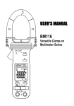
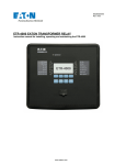
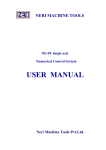
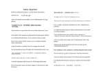
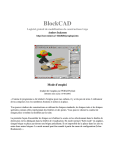
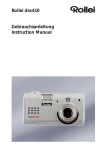
Crystal Touch User’s Manual Crystal Touch User’s Manual Table of Contents 1. Introduction .................................................................................................... 3 1.1. Theory of Operation ................................................................................ 3 1.2. Design Considerations ............................................................................ 3 1.3. Calibration ............................................................................................... 3 2. Hardware Interface ........................................................................................ 3 2.1. Signal Descriptions (SPI) ........................................................................ 3 2.2. I2C Interface ............................................................................................ 4 2.3. VDD .......................................................................................................... 4 2.4. Case Ground ........................................................................................... 4 3. Serial Peripheral Interface (SPI) .................................................................... 4 3.1. Basic Operation....................................................................................... 4 3.2. SPI Timing Requirements........................................................................ 5 3.3. SPI Inter-Message Transfer Delay .......................................................... 6 3.4. SPI Slave Select Line.............................................................................. 6 3.5. Register Access Protocol Using SPI ....................................................... 6 3.6. Register Addresses ................................................................................. 7 3.7. Reading From a Register ........................................................................ 7 3.8. Pipelining Multiple Reads ........................................................................ 8 3.9. Writing To a Register............................................................................... 9 4. Touch Detection........................................................................................... 10 4.1. Sample Rate.......................................................................................... 10 4.2. Z Level .................................................................................................. 10 4.3. Z Idle ..................................................................................................... 10 4.4. Capacitor Charge Time ......................................................................... 10 4.5. Register Descriptions ............................................................................ 13 4.6. Status (0x02) ......................................................................................... 13 4.7. Power and Reset (0x03)........................................................................ 13 4.8. Control (0x04)........................................................................................ 14 4.9. Z Idle (0x0A).......................................................................................... 15 4.10. Calibrate (0x07).................................................................................. 15 4.11. Touch Position Data (0x14, 0x15, and 0x16) ..................................... 15 4.12. Z Level (0x17) .................................................................................... 16 5. Initialization .................................................................................................. 16 6. Power Modes ............................................................................................... 17 6.1. Active Mode........................................................................................... 17 6.2. Low Power Mode................................................................................... 17 6.3. Shutdown Mode .................................................................................... 17 7. Coordinate Scaling....................................................................................... 17 8. Data Ready .................................................................................................. 18 Product descriptions and specifications are subject to change without notice. 12700 Park Central, Suite 750, Dallas, TX 75251 Tel: 972-437-3888 Fax: 972-437- 2562 [email protected] www.OcularLcd.com Page 1 of 19 Crystal Touch User’s Manual Date 4/30/2009 5/7/2009 8/17/2009 Page Rev: 1 Rev: 2 Rev: 3 1/11/2009 Rev: 4 2/22/2010 Rev: 5 3/17/2010 Rev: 6 5/12/2010 Rev: 7 8/24/2010 Rev: 8 Prepared By: Tony Gray Approved By: Dave Nolte Summary Preliminary Release Added X and Y axes inversion Added calibration and electrical sections Added warning to use read-modify-write algorithm Added minimum SPI frequency of 420kHz Added section on setting 1000ns charge time Changed maximum SPI frequency to 4MHz Added Reset bit to Power/Reset register Corrected table for register address 0x16 Added current and temperature specs Moved electrical characteristics, voltage option, quality assurance, and mechanical characteristics sections to individual datasheets. Added §2.3. VDD. Added §2.4. Case Ground. Added §6. Coordinate Scaling. Added §3.3. SPI Inter-Message Transfer Delay Added §3.4. SPI Slave Select Line. In §4.7. added shutdown bit. Added note about Reset on 10.1” touch panel. Added §6. Power Modes. Updated address Corrected address in §4.4. Capacitor Charge Time. 12700 Park Central, Suite 750, Dallas, TX 75251 Tel: 972-437-3888 Fax: 972-437- 2562 [email protected] www.OcularLcd.com Page 2 of 19 Crystal Touch User’s Manual 1. Introduction This document describes the hardware and software interface for Ocular’s Crystal Touch touch panels and applies to all Crystal Touch screen sizes. 1.1. Theory of Operation Ocular’s Crystal Touch touch panels are based on a projected capacitive technology, meaning that a capacitive field is projected through a top layer of glass. This projection mechanism allows the conductive elements to be embedded inside the glass, protecting them from damage. The top surface of Ocular’s Crystal Touch is a high quality piece of custom glass designed for optimum clarity and hardness. When the user places their finger on the glass surface, they alter the capacitive field being projected through the glass. This alteration is detected and used to determine the location of the user’s finger. 1.2. Design Considerations The position of the user’s finger is determined by calculating the centroid of the changes in the electrical field. With some enclosure designs it may be difficult for the user to effectively move the center of their finger into the corners of the touch panel. For this reason, your application should not place any small touch areas in the corners of the screen. When designing an application to work with a finger-actuated touch panel, it is recommended that the application avoid creating small touch areas around the outer edges of the display. Studies show that for the best possible user experience, touch areas should be at least 10mm2 and should be located at least 5mm from the edge of the screen. 1.3. Calibration Each Crystal Touch touch panel undergoes an internal calibration when first powered up. This calibration cancels the effects of the panel’s construction on all touch measurements. Calibration takes around 100ms. The operator must not touch the panel during calibration as this could affect measurement sensitivity. Once the touch panel is powered up, there is no need to execute any subsequent calibration cycles unless the operating parameters of the panel are changed (see section 10 Capacitor Charge Time for an example of when this is necessary). 2. Hardware Interface 2.1. Signal Descriptions (SPI) All of Ocular’s Crystal Touch touch panels with SPI interface have the following hardware pinout: 12700 Park Central, Suite 750, Dallas, TX 75251 Tel: 972-437-3888 Fax: 972-437- 2562 [email protected] www.OcularLcd.com Page 3 of 19 Crystal Touch User’s Manual Pin No. 1 2 3 4 5 6 7 8 9 10 Symbol SCK MISO SS_N DR MOSI GND VDD GND SNSN GND Table 1 Description SPI Clock SPI Master In Slave Out SPI Select Data Ready SPI Master Out Slave In Ground Power Supply Ground Stylus input Ground The mating connector part is Molex 52207-1060 or equivalent. The signals are described below: SCK, MISO, SS_N, MOSI: These pins are part of the SPI communications interface. See section 2.3 for details. SNSN: This pin is for a dedicated stylus input. Leave this pin unconnected (contact Ocular for details on using Crystal Touch with a stylus). 2.2. I2C Interface 2.3. VDD 2.4. Case Ground An I2C interface is available as an alternative to the standard SPI interface. For information on the I2C interface refer to the Crystal Touch I2C Addendum. It is important that the power supply provided to the touch panel be relatively clean, particularly in the low frequency range of 1kHz to 500kHz. Noise on the power supply or GND lines can affect the accuracy of the touch panel. If the system enclosure is metal, the touch panel GND must be connected to the case ground. 3. Serial Peripheral Interface (SPI) 3.1. Basic Operation SPI communication is a four wire bus that includes a slave select line for communicating with multiple devices on the SPI bus. The Crystal Touch controller is designed as a slave device with a select line, two data lines, and a clock line (see Figure 1). The SPI clock signal (SCK) must be initialized to low when idle. To activate Crystal Touch’s SPI bus, pull the slave select line low (SS_N). Data sent by the master is placed on the Master Out Slave In line (MOSI). Data returned by Crystal Touch is placed on the Master In Slave Out line (MISO). Both sets of data are latched on the falling edge of SCK. 12700 Park Central, Suite 750, Dallas, TX 75251 Tel: 972-437-3888 Fax: 972-437- 2562 [email protected] www.OcularLcd.com Page 4 of 19 Crystal Touch User’s Manual Data is presented Most Significant Byte first (MSB). Crystal Touch’s SPI bus supports data rates up to 4Mhz. Figure 1: SPI Signals 3.2. SPI Timing Requirements Timing for the SPI data lines is shown below (see Figure 2). The data exchange is started when the master pulls the SS_N line low. Due to the full duplex nature of the SPI bus, Crystal Touch always returns data at the same time that it is receiving data. The returned byte may be data from the previous command or it may be a filler byte. Item Frequency Period Clock High or Low Time Chip Select Lag Time Inter-Message Transfer Delay Chip Select Lead Time Slave Data Valid Time Slave Data Hold Time Master Data Setup Time Master Data Hold Time 12700 Park Central, Suite 750, Dallas, TX 75251 Tel: 972-437-3888 Fax: 972-437- 2562 Table 4 Symbol ─ TQCYC TSW TLAG TTD TLEAD TV THO TSU THI [email protected] www.OcularLcd.com Min. 0.42 0.25 TQCYC/2 0.030 50 TQCYC ─ TQCYC/2 TQCYC/4 TQCYC/4 Max. 4.0 2.38 ─ ─ ─ ─ 0.500 ─ ─ ─ Unit MHz μs ─ μs μs ─ μs ─ ─ ─ Page 5 of 19 Crystal Touch User’s Manual TTD SS_N ACTIVE TQCYC INACTIVE ACTIVE TSW SCK TLEAD MISO TV THO MSB OUT LSB OUT TSU MOSI TLAG THI MSB IN LSB IN Figure 2: SPI Timing 3.3. SPI Inter-Message Transfer Delay Crystal Touch requires 50μs minimum between transmitted bytes regardless of the baud rate (see TTD in Figure 2). Some processors include a settable delay time between bytes. For those processors that don’t have a settable inter-byte delay time, or for processors whose maximum inter-byte delay time is less than 50μs, the Crystal Touch software driver will have to enforce the inter-byte delay. 3.4. SPI Slave Select Line The slave select line must be low for a least one cycle before the first clock of each byte is transferred. There is no requirement for the slave select line to toggle between bytes or between packets. For example, the slave select line can be driven low at power up and stay low forever. It can also toggle between each byte, as long as it is low for at least one clock cycle before the first clock of each byte. 3.5. Register Access Protocol Using SPI Crystal Touch uses a communication method known as Register Access Protocol (RAP). RAP only has two commands: READ and WRITE. The registers have five bit addresses ranging from 0x00 to 0x1F. Commands are formatted as follows. Table 5 Bit 7 Bit 6 Bit 5 Bit 4 Bit 3 Bit 2 Bit 1 Bit 0 Register Register Register Register Register Read (1) 1 0 Address Address Address Address Address Write (0) Bit 4 Bit 3 Bit 2 Bit 1 Bit 0 12700 Park Central, Suite 750, Dallas, TX 75251 Tel: 972-437-3888 Fax: 972-437- 2562 [email protected] www.OcularLcd.com Page 6 of 19 Crystal Touch User’s Manual 3.6. Register Addresses Only nine of the thirty two registers are used. The rest are reserved and should not be read or written. Table 6 Register Address 0x02 0x03 0x04 0x07 0x0A 0x14 0x15 0x16 0x17 3.7. Description Status Power and Reset Control Calibrate Z Idle X Position Low Byte Y Position Low Byte X and Y Position High Nibbles Z Level Reading From a Register Reading a register requires four SPI exchanges. The host starts by sending the READ command byte. The simultaneous response byte may be data from the previous command or it may be a filler byte. Three additional bytes need to be sent after the READ byte to give Crystal Touch time to process and respond to the command. The response will be sent during the transmission of the final byte. When sending one command at a time the three additional bytes must be 0xFB (0xFB stands for “filler byte”). Example: Read the contents of the Status register (0x02): As shown in section 3.3 SPI Inter-Message Transfer Delay Crystal Touch requires 50μs minimum between transmitted bytes regardless of the baud rate (see TTD in Figure 2). Some processors include a settable delay time between bytes. For those processors that don’t have a settable inter-byte delay time, or for processors whose maximum inter-byte delay time is less than 50μs, the Crystal Touch software driver will have to enforce the inter-byte delay. 3.8. SPI Slave Select Line The slave select line must be low for a least one cycle before the first clock of each byte is transferred. There is no requirement for the slave select line to toggle between bytes or between packets. For example, the slave select line can be driven low at power up and stay low forever. It can also toggle between each byte, as long as it is low for at least one clock cycle before the first clock of each byte. Register Access Protocol Using SPI, a Read command is formatted as 101xxxxx (0xAX). When OR’ed with the register address, the value is 0xA2: 12700 Park Central, Suite 750, Dallas, TX 75251 Tel: 972-437-3888 Fax: 972-437- 2562 [email protected] www.OcularLcd.com Page 7 of 19 Crystal Touch User’s Manual 0xA0 | 0x02 = 0xA2 Send 0xA2 followed by 0xFB three times. The response to the third 0xFB byte will be the contents of register 0x02. Byte 1 2 3 4 Table 7 Command (MOSI) Response (MISO) 0xA2 Note 1 0xFB 0xFB 0xFB 0xFB 0xFB Contents of register 0x02 Note 1: The first response byte may be a filler byte or it may be the response to a previous command. 3.9. Pipelining Multiple Reads Multiple reads can be pipelined for greater throughput by using the auto increment command (0xFC) in place of the filler byte (0xFB) Example: Read the contents of the Position registers (0x14 through 0x16): As shown in 3.3 SPI Inter-Message Transfer Delay Crystal Touch requires 50μs minimum between transmitted bytes regardless of the baud rate (see TTD in Figure 2). Some processors include a settable delay time between bytes. For those processors that don’t have a settable inter-byte delay time, or for processors whose maximum inter-byte delay time is less than 50μs, the Crystal Touch software driver will have to enforce the inter-byte delay. 3.10. SPI Slave Select Line The slave select line must be low for a least one cycle before the first clock of each byte is transferred. There is no requirement for the slave select line to toggle between bytes or between packets. For example, the slave select line can be driven low at power up and stay low forever. It can also toggle between each byte, as long as it is low for at least one clock cycle before the first clock of each byte. Register Access Protocol Using SPI, a Read is formatted as 101xxxxx (0xAX). When OR’ed with the first register address, the value is 0xB4 0xA0 | 0x14 = 0xB4 Send 0xB4 followed by 0xFC four times. Then send a single 0xFB to terminate the sequence. The response to the third 0xFC will be the contents of register 0x14. The response to the fourth 0xFC will be the contents of register 0x15. The response to the last byte, 0xFB, will be the contents of register 0x16. 12700 Park Central, Suite 750, Dallas, TX 75251 Tel: 972-437-3888 Fax: 972-437- 2562 [email protected] www.OcularLcd.com Page 8 of 19 Crystal Touch User’s Manual Byte 1 2 3 4 5 6 Table 8 Command (MOSI) Response (MISO) 0xB4 Note 1 0xFC 0xFB 0xFC 0xFB 0xFC Contents of register 0x14 0xFC Contents of register 0x15 0xFB Contents of register 0x16 Note 1: The first response byte may be a filler byte or it may be the response to a previous command. 3.11. Writing To a Register Writing to a register requires two SPI exchanges. The host starts by sending the WRITE command byte. The simultaneous response byte may be data from the previous command or it may be a filler byte. The host then sends the byte being written to the register. The simultaneous response byte is 0xFB. Multiple writes must be sent as consecutive single writes. Example: Write the value 0x03 to the Control register (0x04): As shown in 3.3 SPI Inter-Message Transfer Delay Crystal Touch requires 50μs minimum between transmitted bytes regardless of the baud rate (see TTD in Figure 2). Some processors include a settable delay time between bytes. For those processors that don’t have a settable inter-byte delay time, or for processors whose maximum inter-byte delay time is less than 50μs, the Crystal Touch software driver will have to enforce the inter-byte delay. 3.12. SPI Slave Select Line The slave select line must be low for a least one cycle before the first clock of each byte is transferred. There is no requirement for the slave select line to toggle between bytes or between packets. For example, the slave select line can be driven low at power up and stay low forever. It can also toggle between each byte, as long as it is low for at least one clock cycle before the first clock of each byte. Register Access Protocol Using SPI, a Write is formatted as 100xxxxx (0x8X). When OR’ed with the register address, the value is 0x84 0x80 | 0x04 = 0x84 Send 0x84 followed by 0x03. 12700 Park Central, Suite 750, Dallas, TX 75251 Tel: 972-437-3888 Fax: 972-437- 2562 [email protected] www.OcularLcd.com Page 9 of 19 Crystal Touch User’s Manual Byte 1 2 Table 9 Command (MOSI) Response (MISO) 0x84 Note 1 0x03 0xFB Note 1: The first response byte may be a filler byte or it may be the response to a previous command. NOTE: Many registers contain reserved bits that are not used for this application. Changing any reserved bits could result in unexpected behavior. When writing to a register, always use a read-modify-write algorithm that preserves the values of all reserved bits. 4. Touch Detection 4.1. Sample Rate 4.2. Z Level Crystal Touch samples the touch panel 100 times per second, or every 10ms. If the Data Ready bit is cleared between scans and there is new data to report, the touch data registers will be updated every 10ms. If the Data Ready bit is not cleared, the new data is discarded. The Z level is a measure of how much the capacitive field has changed. When no finger is near the touch panel, the Z level will be at or near 0. As a finger approaches the top of the touch panel, the Z level will begin to increase. The Z level will continue to increase as more of the surface area of the finger comes into contact with the top surface of the touch panel. Position data is generated for any Z level greater than 0. Therefore, it is up to the software driver to determine the minimum Z levels that constitute a touch and a release. For more information see Appendix A – Software Driver Sample. 4.3. Z Idle 4.4. Capacitor Charge Time Once the finger is removed, Crystal Touch can be configured to either immediately cease sending position data, or it can send a specified number of empty packets. This feature is referred to as Z Idle. If configured to send empty packets, the Data Ready signal will be asserted every 10ms until all the empty packets have been generated. The default time that the capacitors in the panel are allowed to charge up is 500ns. This default value works correctly for all touch panels except the 7” diagonal touch panel. For 7” touch panels the capacitor charge time must be changed to 1000ns. Changing the capacitor charge time involves reading and writing several twobyte extended register addresses. Reading and writing an extended address is accomplished by writing the two bytes of the address to a pair of standard registers, then writing a command to a third register. Each extended memory 12700 Park Central, Suite 750, Dallas, TX 75251 Tel: 972-437-3888 Fax: 972-437- 2562 [email protected] www.OcularLcd.com Page 10 of 19 Crystal Touch User’s Manual access takes several milliseconds to process. Note that the POST bit in the Status register needs to be cleared after each extended memory access. To change the capacitor charge time to 1000ns, write 0x08 to extended memory address 0x0EE. This can be accomplished by transmitting the following sequence of bytes to the Crystal Touch touch panel: 12700 Park Central, Suite 750, Dallas, TX 75251 Tel: 972-437-3888 Fax: 972-437- 2562 [email protected] www.OcularLcd.com Page 11 of 19 Crystal Touch User’s Manual MOSI Table 10 Description Write to register 0x03 Disable finger tracking 0x83 0x08 Wait 10ms 0x9C Write to register 0x1C 0x00 Upper address byte 0x9D Write to register 0x1D 0xEE Lower address byte 0x9E Write to register 0x1E 0x01 Read command 0xBE Read from register 0x1E 0xFB Filler byte 0xFB Filler byte 0xFB Filler Byte Repeat reading register 0x1E until it contains 0x00 0xBB Read from register 0x1B 0xFB Filler byte 0xFB Filler byte 0xFB Filler byte 0x9B Write to register 0x1B (Value & 0xF0) | 0x08 Set charge time to 1000ns 0x9E Write to register 0x1E 0x02 Write command 0xBE Read from register 0x1E 0xFB Filler byte 0xFB Filler byte 0xFB Filler Byte Repeat reading register 0x1E until it contains 0x00 0x82 Write Status Register 0x00 Clear Status register 0x83 Write to register 0x03 0x00 Enable finger tracking 0x87 Write to Calibration 0x01 Start calibration Wait 100ms 0xA2 Read register 0x02 0xFB Filler byte 0xFB Filler byte 0xFB Filler byte Continue reading register 0x02 until it is non-zero 0x82 Write to register 0x02 0x00 Clear status 12700 Park Central, Suite 750, Dallas, TX 75251 Tel: 972-437-3888 Fax: 972-437- 2562 [email protected] www.OcularLcd.com MISO Description 0xFB Filler byte 0xFB Filler byte 0xFB 0xFB 0xFB 0xFB 0xFB 0xFB 0xFB 0xFB 0xFB 0x00 Filler byte Filler byte Filler byte Filler byte Filler byte Filler byte Filler byte Filler byte Filler byte Contents of register 0x1E 0xFB 0xFB 0xFB Value 0xFB 0xFB 0xFB 0xFB 0xFB 0xFB 0xFB 0x00 Filler byte Filler byte Filler byte Contents of register 0x0EE Filler byte Filler byte Filler byte Filler byte Filler byte Filler byte Filler byte Contents of register 0x1E 0xFB 0xFB 0xFB 0xFB 0xFB 0xFB Filler byte Filler byte Filler byte Filler byte Filler byte Filler byte 0xFB 0xFB 0xFB Value Filler byte Filler byte Filler byte Status 0xFB 0xFB Filler byte Filler byte Page 12 of 19 Crystal Touch User’s Manual 4.5. 4.6. Register Descriptions Status (0x02) Bit Name Read/Write Initial Value 7 6 5 Table 11 4 3 POST R/W 0 2 DR R/W 0 1 0 Bit 3 – POST: Power On Self Test The POST bit indicates successful completion of the power on self test (POST) following a reset. It is cleared by writing to the register. The POST bit should only be polled if the host cannot access the hardware Data Ready signal (see section 7). Bit 2 – DR: Data Ready The DR bit indicates when new position data is ready. As long as no finger is detected, this bit stays low. When a finger is detected on the surface of the touch panel, this bit is set high every 10ms as long as the finger is present. It is cleared by writing to the register. The DR bit should only be polled if the host cannot access the hardware Data Ready signal (see section 7). NOTE: When clearing the Status register, a read-modify-write algorithm is not required. Simply write 0x00 to the register to clear it. 4.7. Power and Reset (0x03) Bit Name Read/Write Initial Value 7 6 5 Table 12 4 3 2 LP W 0 1 SD W/R 0 0 RESET W 0 Bit 2 – LP: Low Power The LP bit is used to enter lower power mode. After a 1 is written to this bit, Crystal Touch will enter low power mode five seconds after the last touch is sensed. Power consumption in low power mode is approximately 40μA. Crystal Touch will check for a touch every 300ms. If a touch is detected or a SPI message is received, it will switch back to Active mode. Once Crystal Touch enters Low Power mode, it can take up to 5ms for it to switch back to Active mode as the result of an incoming SPI message. If Crystal Touch is in Low Power mode, the host should either send the first message twice with a minimum 5ms spacing between messages, or send the first byte of the message followed by a 5ms pause before transmitting the rest of the message. 12700 Park Central, Suite 750, Dallas, TX 75251 Tel: 972-437-3888 Fax: 972-437- 2562 [email protected] www.OcularLcd.com Page 13 of 19 Crystal Touch User’s Manual Bit 1 – SD: Shutdown The SD bit is used to enter shutdown mode. After a 1 is written to this bit, Crystal Touch will enter shutdown mode immediately. Power consumption in shutdown mode is approximately 1μA. Crystal Touch will not respond to touches in shutdown mode. To return to Active mode, set the shutdown bit to 0. Bit 0 – RESET: Reset Write a 1 to this bit to force a reset of the touch panel controller. Follow the standard Initialization process following a reset. NOTE: Reset is not supported on the 10.1” touch panel. 4.8. Control (0x04) Bit Name Read/Write Initial Value 7 6 YINV XINV R/W R/W 0 0 Table 13 5 4 3 2 1 A/R R/W 0 0 EN R/W 0 Bit 7 – YINV: Y Axis Invert Writing a 0 to this bit results in standard reporting for the Y position data (0 to 1535). Writing a 1 to this bit inverts the Y position data (1535 to 0). The correct setting for this bit depends on the orientation of your Crystal Touch module. Bit 6 – XINV: X Axis Invert Writing a 0 to this bit results in standard reporting for the X position data (0 to 2047). Writing a 1 to this bit inverts the X position data (2047 to 0). The correct setting for this bit depends on the orientation of your Crystal Touch module. Bit 1 – A/R: Absolute / Relative Mode Writing a 0 to this bit puts Crystal Touch in Relative (mouse) mode. Writing a 1 to this bit puts Crystal Touch in Absolute mode. Ocular recommends always using Absolute mode. Bit 0 – EN: Enable Writing a 0 to this bit disables Crystal Touch. Writing a one to this bit enables Crystal Touch. 12700 Park Central, Suite 750, Dallas, TX 75251 Tel: 972-437-3888 Fax: 972-437- 2562 [email protected] www.OcularLcd.com Page 14 of 19 Crystal Touch User’s Manual 4.9. Z Idle (0x0A) Bit Name Read/Write Initial Value 7 6 5 Table 14 4 3 ZI R/W 0x1E (30) 2 1 0 Bits 7 to 0 – ZI: Z Idle The number in this register defines how many times Crystal Touch will present empty position data to the host after the finger has been lifted from the touch panel. An empty position is defined as both the X and Y positions set to 0. Because new packets are ready every 10ms, tap times can be calculated easily by counting the number of empty packets received following a touch. When set to 0, this register prevents any empty packets from being sent. In this case the position registers will contain the last sensed location until a new finger presence is detected. 4.10. Calibrate (0x07) Bit Name Read/Write Initial Value 7 Table 15 5 4 6 3 2 1 0 CAL R/W 0 Bit 0 – CAL: Calibrate Writing a 1 to this bit forces a self-calibration cycle. Calibration takes approximately 100ms. When calibration is complete, the POST bit in the Status register will be set. The Status register must be cleared to continue normal operation. 4.11. Touch Position Data (0x14, 0x15, and 0x16) Bit Name Read/Write Initial Value 7 6 Table 16 5 4 3 XDLB R 0xFF 2 1 0 Address 0x14::Bits 7 to 0 – XDLB: X Position Low Byte The lower eight bits of the twelve bit X position data. 12700 Park Central, Suite 750, Dallas, TX 75251 Tel: 972-437-3888 Fax: 972-437- 2562 [email protected] www.OcularLcd.com Page 15 of 19 Crystal Touch User’s Manual Bit Name Read/Write Initial Value 7 Table 17 5 4 3 YDLB R 0xFF 6 2 1 0 Address 0x15::Bits 7 to 0 – YDLB: Y Position Low Byte The lower eight bits of the twelve bit Y position data. Bit Name Read/Write Initial Value 7 Table 18 5 4 6 3 2 YPHN R 0xFF 1 0 XPHN R 0xFF Address 0x16::Bits 7 to 4 – YPHN: Y Position High Nibble The upper four bits of the twelve bit Y position data. Address 0x16::Bits 3 to 0 – XPHN: X Position High Nibble The upper four bits of the twelve bit X position data. For all Crystal Touch touch panels, the X coordinate ranges from 0 to 2047 and the Y coordinate ranges from 0 to 1535. It is the host’s responsibility to scale these values to the display resolution being used. 4.12. Z Level (0x17) Bit Name Read/Write Initial Value 7 Table 19 5 4 6 3 2 1 0 ZL R 00 Bits 5 to 0 – ZL: Z Level In addition to X and Y position data, Crystal Touch measures finger presence on the touch panel surface. The signal strength of the finger is called Z level. A smaller finger results in a lower Z level and a larger finger gives a larger Z level. See section 4.2 Z Level. Z level values range from 0 to 63. 5. Initialization Crystal Touch performs a power on self test (POST) and a self calibration following a reset. If the POST completes successfully, the POST bit in the Status register (0x02) is set and the Data Ready signal is set high. 12700 Park Central, Suite 750, Dallas, TX 75251 Tel: 972-437-3888 Fax: 972-437- 2562 [email protected] www.OcularLcd.com Page 16 of 19 Crystal Touch User’s Manual Once the POST has completed, Crystal Touch needs to be set to absolute mode and enabled. This is done by writing the value 0x03 to the Control register (0x04). You may also need to invert the X or Y axes which are controlled by the highest two bits in this register (see section 4.8 Control (0x04)). Next, clear the POST bit, Data Ready bit, and Data ready signal by writing the value 0x00 to the Status register (0x02). If using a 7” panel, next change the capacitor charge time to 1000ns (see section 4.4 Capacitor Charge Time). 6. Power Modes 6.1. Active Mode Active mode is the normal operational mode. Crystal Touch defaults to this mode following a power up or reset. In this mode Crystal Touch continually scans the touch panel for touches and reports the data. To switch from Active mode to Low Power or Shutdown mode, set the appropriate bit in the Power and Reset register. See §4.7 for more details. 6.2. Low Power Mode In Low Power mode Crystal Touch continues to monitor the touch panel for touches. When a touch is detected, Crystal Touch transitions to Active mode to report the touch. Crystal Touch can also be forced back into active mode by setting the bit to 0. Once in Active mode, Crystal Touch stays awake until the Low Power or Shutdown bit is set again. See §4.7 for more details. 6.3. Shutdown Mode Shutdown mode is the lowest power mode available. In Shutdown mode Crystal Touch does not respond to any touches. Once in Shutdown mode, Crystal Touch stays in this mode until the Shutdown bit is set to 0. See §4.7 for more details. 7. Coordinate Scaling Although the controller is theoretically capable of returning coordinates between (0, 0) and (2047, 1535), due to the geometric construction of the touch panels the actual reported coordinates in the corners of the touch panel are typically between (64, 64) and (1983, 1471). This origin shift must be accounted for when scaling the panel’s coordinates to the display’s coordinates. First, shift the reported coordinates to an origin of (0, 0) by subtracting 64 from each value. Then divide by the maximum coordinate in X and Y. Keep in mind that the maximum coordinates should 12700 Park Central, Suite 750, Dallas, TX 75251 Tel: 972-437-3888 Fax: 972-437- 2562 [email protected] www.OcularLcd.com Page 17 of 19 Crystal Touch User’s Manual also be shifted by 64, meaning that the maximum X value is 1983 – 64 = 1919; the maximum Y value is 1471-64 = 1407. The following example scales the panel coordinates to a 16:9 display with a width (X) of 533 and a height (Y) of 300: // check for underflow if (PanelX < 64) PanelX = 0; else PanelX -= 64; if (PanelY < 64) PanelY = 0; else PanelY -= 64; // scale coordinates DisplayX = (PanelX * 533) / 1919; // 1919 = 2047 - 128 DisplayY = (PanelY * 300) / 1407; // 1407 = 1535 - 128 // check for overflow if (DisplayX > 532) DisplayX = 532; if (DisplayY > 299) DisplayY = 299; Note the underflow check on the panel coordinates and the overflow check on the display coordinates. This is required because the panel might report coordinates slightly less than (64, 64) or slightly greater than (1983, 1471). 8. Data Ready In addition to the Data Ready software flag in the Status register (0x02), there is also a Data Ready hardware signal (DR). Crystal Touch drives this signal high when new position data is available. New position data may be available as often as every 10ms. Once the new data has been read, write 0x00 to the Status register (0x02) to clear the DR signal. This signal also indicates that a Power On Self Test (POST) has completed successfully following a reset. See section 5 Initialization. 12700 Park Central, Suite 750, Dallas, TX 75251 Tel: 972-437-3888 Fax: 972-437- 2562 [email protected] www.OcularLcd.com Page 18 of 19 Crystal Touch User’s Manual Appendix A – Software Driver Sample The following sample code demonstrates how to use the Z level to determine when a touch and release event occur. bool TouchPanelDataIsReady(void); struct POSITION_DATA { uint16 X, Y; uint8 ZLevel; }; void GetFingerPosition(struct POSITION_DATA *Position); /* These are typical numbers. You made need to tune them to your application and enclosure. /* #define MIN_Z_LEVEL_FOR_TOUCH 25 #define Z_LEVEL_RELEASE_THRESHOLD 20 static bool FingerIsPresent = FALSE; if (TouchPanelDataIsReady()) { struct POSITION_DATA FingerPosition; GetFingerPosition(&FingerPosition); if (FingerIsPresent) { if (FingerPosition.ZLevel < Z_LEVEL_RELEASE_THRESHOLD) { FingerIsPresent = FALSE; //////////////////////////////// // post finger up event to OS // //////////////////////////////// } /* if-then */ else { ///////////////////////////////////// // post finger position data to OS // ///////////////////////////////////// } /* if-else */ } /* if-then */ else { if (PositionData.ZLevel > MIN_Z_LEVEL_FOR_TOUCH) { FingerIsPresent = TRUE; /////////////////////////////////////////// // post finger down event and data to OS // /////////////////////////////////////////// } /* if-then */ } /* if-else */ } /* if-then */ 12700 Park Central, Suite 750, Dallas, TX 75251 Tel: 972-437-3888 Fax: 972-437- 2562 [email protected] www.OcularLcd.com Page 19 of 19