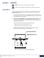
1
E . Y E A
ER M Y T A Y W O M MA DY ES T .
Y
W A M A Y S T C C E
N EM MA N ES ME S, T N T ER ~ M DY ST & D RS ~ M NA M MA DY E MO S, MA NE T & ER . ~ DY S & D TER ~ M
S
I
Y
AM ~ DW AM S T E S T T IN IC E & S ID NA E Y ~ I M S, TI NE ST M IN T
SY DY S ~ MI NA ST YN S ~ ID
D
S
I
I
N
M
E
,
C
&
D
C
C
I
D
C
O
C
E
D
M
D
O
N
~
Y
W
E
Y Y
W
I
A
D M E A
S &
R .
S A
.
IN TIC YN ST ME NC DY ST DY S ~ M YN ST NA DY ES OM , I MA YN ES ME C. DY YS DY TER ~ M DY ST NA DY W O M MA DY
N
A
E & T . ~ N EM N ~
C
T TE ~ N T N S I N EM M N ES M S, T
I M E M N T E C T E
R . ~ DYN SY DY ER M AM S AM DY DW O MS AT E S & TE . ~ IC SY & RS MID AM EM AM ~ DW AM S, ATI E S T ETE IN IC
&
C
S M A S
M
,
D
S I
A N
D
TE NA ~ DW OM IN TI E ES E , IN IC YS YN RS MI YN STE DY ~ WE OM S, I AT DY ES OM INC C D YS D RS . ~
~
I
D
M
N
N D W O M M D E E C C S T TE C D T
N
AM Y
. ~ D Y & R . ~ Y E AM ~ D DW AM MS AM DY ST ET NC IC E T & ET . ~ YN TEM YN ~ M
T
Y
S
A
S
E
M
D
N
AM D
E
S
M
N
E
.
N S
, T N T
M A
A Y E O ,
& R ~ Y S D E
T D S
M Y
A
S, ATI E S T & ETE INC IC E S & D RS ID NA EM YN ~ MID M S, I TIC NE ST M INC ATI E S D S M NA YS YN RS ID MO S, I AT YN
IN C D YS D R . DY YS Y ~ D W MO S A DY W OM NC D S & ET . C D YS YN ~ D ID M TE AM ~ D W ME NC IC
ET C. YN TE YN S ~ ~ M NA TE NA Y ES M , IN MA NE ES ET . ~ YN YS DY ER ~ M YN TE AM YN WE OM MS A Y ES TE . ~ D
T N S
T
M N T E
T
~
M
, T N T
D ER M AM MS AM DY IDW O MS AT E S & TE C. ~ IC SY & ER MID AM EM AM ~ IDW AM MS ATI E S ST ET IN IC E S & RS MID
YN S ID O ,
AT NE E M , I IC Y DY R
D ST D S
W OM S, AT DY ES OM , IN C D YS & D ER C. DY YS DY ~ D
I
M
Y
E
S
~
N
Y
N
~
W
M
S
S
A
I
S ~
N
M MA DY ES ET C. C D SY T & TE C. DY TE NA ~ D IDW NA EM NA DY ES ET INC IC NE T & ET C. ~ YN TE YN ~ M NA TE AM Y
T
R
M
M
M
S
S, T N T E ~
M
~ N M
N
M A M AM D ID
A Y E O ,
& ER . ~ DY S D E
O M A
M Y ST D S
A
TE INC IC E S & D RS ID NA EM YN ~ MID M S, I TIC NE ST M INC ATI E S D S M NA YS YN RS ID MO S, I AT YN WE M S, I TI
R . ~ DY YS Y ~ D W MO S AM DY W OM NC D SY & ET . ~ C D YS YN ~ D IDW M TE AM ~ D WE ME NC IC E S ST ET NC
O M
YN S ~ M NA T NA Y ES M , IN A NE ES E . ~ Y S DY ER M Y TE AM Y
AT YN ST TE . ~ DY YS & ER .
S
E
M
T
N
E
N
N
T
N
E
T
T
N
M
T
S
M
,
S
C
M A
I
I
E
T D S
M
A
M
E
A
S, M DYN DW OM S AT E S & D TE . ~ IC SY & RS MID M EM AM ~ DW AM S, TI E S T & TE INC IC E S & D RS ID NA EM YN ~
IN ATI E ES E , IN IC YS Y RS M DY ST DY ~ W OM S, AT DY ES OM IN C D YS D R . ~ DY YS Y ~ D W MO S AM
ET C. C D SY T TE C. DY TE NA ~ IDW NA EM NA DY ES ET INC IC NE T ET C. YN TE YN S ~ M NA TE NA Y ES M , IN A
ER ~ M Y ST & D RS ~ M NA M MA DY E MO S, MA NE T & ER . ~ DY S & D ER ~ M A MS AM DY ID MO M MA NE T & ET C.
AM S ID NA E Y ~ I M S, TI NE ST M IN T
S M NA YS YN S ID MO , I AT N WE M S, I TIC SY D ER ~
D
S
D
I
N
M
C
C
I
E S E N
C
O
T
D W
N
Y Y ~ I
& E
S Y S
A ~ W M
A ~ W M N
, I TI DY E OM S, I AM YN E ME C. DY SYS D TE . ~ DY ST NA DY DW MO EM M DY ES ET C. IC D SY T & TE C. DY TE NA ~ D
S
A
A
N C
Y
R
C D NE T ET NC TI E S ST TE ~ M NA TE NA RS MID NA EM MA NE ES ME S, I TI NE T & ER ~ M YN ST D S ~ M NA MS MA
R . ~ YN S & D ER . ~ C D YS & D RS ID MO MS M ~ D W MO S, TIC SY T & TE NC C D S D S ~ ID AM EM YN ~ D ID MO , IN TIC
S M A Y Y S M Y T Y ~ W M , A Y E
W O S A Y W M C
Y YS Y
S M IN D S D R .
T
S
D
M ~ D IDW MO TE NA ~ IDW NA EM NA DY ES ET INC IC NE T ET C. YN TE YN S ~ ~ M NA TE NA YN ES M , IN MA NE ES ET . ~
AT Y E M M M DY E M S M N T E . D S &
ER ~ M A MS AM DY ID MO M MA E T & ET C. TIC S T & ER
,
N
D
A
&
R
O
~
Y
A
E
E
Y
S
S
I
S
N
I
IN C E T T , TI E T M N TI S D S M N S YN S ID MO ,
AT NE WE M S, I TIC SY DY ER ~ M D YST D S
I
C
A
C
T
Y
C DY SY & ER IN C
S
N
Y
E
Y
~
I
Y
~ W M
S E N
&
S
R . ~ N S D S C. DY SYS D TE . ~ DY ST NA DY DW MO EM AM DY ES ET C. IC D SY T & TE C. DY TE NA ~ IDW NA EM NA
S M A T YN ~ ~ N T Y R M N E M N E M S AT N T E ~
R
M D
M S
~ ID M EM A D M A E NA S ID A M A E ST E , I IC E & R M YN ST DY S ~ M NA MS AT YN ES O , I
E
T
O
M
AM DY W M S M YN ID MO MS M ~ D W MO S, IC SY & TE NC D S D S ~ IDW AM M N ~ D ID O , IN IC E T & ME NC
,
E
A
Y
W
AT NE ES ET IN TIC E S WE ME , IN ATI YN ST ME INC DY ST DY RS . ~ YN ST YN D E OM S, I AM YN E ME C. DY SYS D TE
C
C IC S T E C.
Y R
A Y S
S
M A
S
N A
.~
& R
D YS T TE C. D E S & D TE . ~ NA EM NA ~ D ID M EM MA NE T & ET C. TIC E S T TE ~ M NA TE NA
Y
~
S
& R
Y T & R ~ Y
M
O
M
D S D
S MI YN TE YN ~ MI NA EM D S M NA YS YN RS ID MO S, I AT YN WE M S, I TIC SY D ER ~ M D YS D S IDW MO MS M
Y
E S E N
T
Y T Y ~
S
D D
Y ~ ID
M ,
~ D
S
M
A ~ W M N
M
M DY WE AM S AM YN WE O S, I NA DY W MO EM M DY ES ET C. IC D SY T & TE C. DY TE NA ~ D IDW NA EM NA DY ES ET INC
AT N S O , I AT E S M N M N E M S AT N T E ~
YN ST D RS ~ M NA MS MA Y E MO S, MA NE T & ER .
N
,
S
C
M
E
M
A
T
E
R
T
E
E
S
I
E
I
I
I
& S I
T T N C
IN C
E Y ~
T .
T
M , T N S
S
E C C
M IN T
C D SY & D TE . ~ D YST & D ER ~ M IC SY & ER C. DY SY DY ~ DW AM MS NA D IDW O IN IC E S T & ET C. IC SY DYN
TE . ~ YN ST YN RS MI YN EM YN S ~ ID DY ST DY S ~ M NA ST NA DY ES OM , IN MA YN ES ME C. DY YS DY ER ~ M DY ST A
R MID AM EM AM ~ DW AM S AM D WE NA EM NA ~ D ID M EM M NE T ET C TI E S T TE ~ M NA TE NA S ID NA EM M
S
&
,
A
. C
& R
O
M
S
Y
O
YN ~ WE M S, I AT DY ES OM INC AT NE ST MO S, I AT YN WE M S, I TIC SY D ER ~ M D YS D S IDW MO MS MA ~ D WE MO , I
N
Y
E
T
I
Y
E
S
~
N
Y
D
N
I
,
Y
E
T
M
N
E
C
S M
T
S
& M
S
C
S
I
S, AM YN T TE C. D E S & D TE . ~ D SY D ET C. C D SY T & TE C. DY TE NA ~ D IDW NA EM NA DY ES ET INC IC NE T & ET
IN AT E S & D RS ~ M YN YS Y RS MID YN ST YN ER ~ M YN ST D RS ~ M NA MS MA Y E MO S, MA NE T & ER . ~ DY SY D
ET C. IC Y YN ~ ID AM TE NA ~ W AM EM AM S ID A EM YN ~ ID M , I TIC NE ST M INC TI S D S M NA S YN
ER ~ M DY ST A DY W O M MA DY ES O S, AT ~ D W MO S AM DY W OM NC D SY & ET . ~ C D YS YN ~ D IDW M TE
N S ID NA EM MA NE ES ME S, I TI NE T ME IN IC YN ES M , IN A NE ES ET . ~ YN ST DY ER M YN TE AM YN E OM MS
AM ~ W M S T
& T C D E T ET C TI S T E M A E N S ID A M A E S E ,
S T T N C
S
& E . ~ C Y & R ID M M AM ~ W M S T
T T
A D E O , I IC Y & ER C. D Y DY ER . ~ Y
S
I S
Water-Cooled
Eddy Current Dynamometers
USER MANUAL
Dynamometer Model: Midwest
Dynamatic
Type:
Dry Gap Wet Gap
Model #: _____________________
Serial #: ___________________________
HP Rating: ___________________
Speed Range: ______________________
Job #: ___________________
www.dynesystems.com
DPD-002-04
From Dyne Systems, Inc.
Dyne Systems is the sole owner of original OEM drawings and specifications for both Midwest
Dynamometer & Engineering Company and Eaton Dynamatic Dynamometers. Midwest and
Dynamatic dynamometers built their reputations on being robustly engineered for a long life of
demanding service.
Going back to the 1930s, Midwest and Dynamatic have been time-honored and well-respected
manufacturers of eddy current dynamometers. Today’s materials, technology, engineering,
and manufacturing techniques have all contributed to significant improvements in eddy current
dynamometer design and manufacturing. Midwest and Dynamatic product lines provide a complete
range of dynamometers from 5 to 5,000 horsepower.
Our dynamometer team specializes in manufacturing and remanufacturing Midwest and Dynamatic
dynamometers, with the capability of restoring model years as far back as the 1930s to today’s
improved OEM specifications.
NOTE: This manual is intended for use by qualified personnel only. All Dyne Systems’ approved
drawings (if included) and specific instructions for this equipment must take precedence over
general information contained in this manual.
Thank you for purchasing this product from Dyne Systems. Our staff is at your disposal, should you
need information or support that is not found in this manual.
CONTROLS, DYNAMOMETERS, SYSTEM INTEGRATION AND TEST CELL AUTOMATION
Dyne Systems, Inc. • W209 N17391 Industrial Drive • Jackson, Wisconsin 53037
Toll Free: 800.657.0726 • www.dynesystems.com
Dyne Systems • WATER-COOLED EDDY CURRENT DYNAMOMETERS
DPD-002-04 • © Copyright Dyne Systems, Inc.
Introduction
1
2
Dyne Systems • WATER-COOLED EDDY CURRENT DYNAMOMETERS
DPD-002-04 • © Copyright Dyne Systems, Inc.
TABLE OF CONTENTS
SECTION 1:
GENERAL INFORMATION
6
SAFETY...................................................................................................................................6
RECEIVING INSPECTION......................................................................................................6
DAMAGE CLAIMS...................................................................................................................7
IDENTIFY YOUR DYNAMOMETER.........................................................................................7
HANDLING..............................................................................................................................7
TRAINING................................................................................................................................7
WARRANTY VALIDATION.......................................................................................................8
SECTION 2:
PRODUCT DESCRIPTION
9
PRINCIPLE OF OPERATION..................................................................................................9
CONSTRUCTION....................................................................................................................9
BEARINGS............................................................................................................................ 10
EDDY CURRENT THEORY................................................................................................... 11
COOLING PRINCIPLES........................................................................................................ 13
DRY GAP......................................................................................................................................13
WET GAP.....................................................................................................................................13
COOLING SYSTEM............................................................................................................... 14
LUBRICATION....................................................................................................................... 15
SAFETY DEVICES................................................................................................................ 15
SPEED MEASUREMENT...................................................................................................... 15
STATIC TORQUE TEST (ROTOR LOCK).............................................................................. 15
TORQUE MEASUREMENT................................................................................................... 16
SECTION 3:
INSTALLATION & SETUP
17
LOCATION AND ENVIRONMENT......................................................................................... 17
SITE PREPARATION............................................................................................................. 17
FOUNDATION AND MOUNTING........................................................................................... 17
UNIT PREPARATION............................................................................................................. 18
MOUNTING THE DYNAMOMETER...................................................................................... 19
SHAFT TIR MEASUREMENT................................................................................................20
SHAFT AND COUPLING HUB PREPARATION....................................................................21
ALIGNMENT FOR SHAFT COUPLING.................................................................................22
ANGULAR MISALIGNMENT....................................................................................................... 23
OFFSET MISALIGNMENT.......................................................................................................... 24
SHAFT CRITICAL SPEED AND OVERHUNG LOADS..........................................................24
ELECTRICAL WIRING...........................................................................................................24
COOLING SUPPLY AND MEDIUM........................................................................................24
COOLING SYSTEM PIPING..................................................................................................25
LUBRICATION SYSTEMS......................................................................................................25
LOAD MEASURING SYSTEM...............................................................................................27
Dyne Systems • WATER-COOLED EDDY CURRENT DYNAMOMETERS
DPD-002-04 • © Copyright Dyne Systems, Inc.
Table of Contents
3
TABLE OF CONTENTS (CONTINUED)
SECTION 4:
CHECKS AND ADJUSTMENTS
28
ELECTRICAL WIRING...........................................................................................................28
CARCASS MOVEMENT........................................................................................................28
ANTI-ROTATION SAFETY STOP...........................................................................................29
LOAD STRUT AND ROD ENDS............................................................................................29
WATER PURITY.....................................................................................................................30
AUTOMATIC PIPING COOLANT SYSTEM............................................................................31
Y-STRAINER..........................................................................................................................31
SOLENOID VALVE.................................................................................................................32
COOLANT PRESSURE SWITCH..........................................................................................32
CONSTANT FLOW VALVE.....................................................................................................32
COOLANT MODULATING VALVE.........................................................................................33
EXIT COOLANT TEMPERATURE SWITCH..........................................................................34
COOLANT FLOW SWITCH...................................................................................................34
CONSTANT LEVEL OILERS.................................................................................................35
PRESSURIZED RE-CIRCULATING OIL SYSTEM................................................................35
MAGNETIC PICK-UP.............................................................................................................36
SECTION 5:
DEAD WEIGHT CALIBRATION
37
SECTION 6:
OPERATION
39
INITIAL START-UP.................................................................................................................39
LOADING...............................................................................................................................40
NORMAL OPERATION AND PERFORMANCE PROFILE....................................................40
SECTION 7:
MAINTENANCE
41
CHECK LIST..........................................................................................................................41
INSPECTION.........................................................................................................................41
CLEANING.............................................................................................................................42
LUBRICATION.......................................................................................................................42
MAINTENANCE SCHEDULE GUIDELINES.........................................................................43
STORAGE..............................................................................................................................45
SECTION 8:
4
TROUBLESHOOTING
Dyne Systems • WATER-COOLED EDDY CURRENT DYNAMOMETERS
DPD-002-04 • © Copyright Dyne Systems, Inc.
46
Table of Contents
SECTION 9:
PARTS AND SERVICE
47
SPARE PARTS.......................................................................................................................47
ORDERING INSTRUCTIONS................................................................................................47
FIELD SERVICE....................................................................................................................47
REPAIR SERVICE.................................................................................................................47
SHIPPING REQUIREMENTS................................................................................................47
ON-SITE REPAIRS................................................................................................................47
SECTION 10:
PRODUCT WARRANTY
48
WARRANTY, REMEDIES AND LIMITATIONS:......................................................................48
APPENDIX A:
DEFINITIONS/FORMULAS
49
APPENDIX B:
ACRONYMS
50
Dyne Systems • WATER-COOLED EDDY CURRENT DYNAMOMETERS
DPD-002-04 • © Copyright Dyne Systems, Inc.
Table of Contents
5
SECTION 1:
GENERAL INFORMATION
Dyne Systems, Inc. (hereafter referred to as DS) is the sole Original Equipment Manufacturer
(OEM) of Midwest and Dynamatic brand Eddy Current dynamometers. This manual,
intended for qualified personnel only, contains instructions for proper handling, installation,
operation, and maintenance of both Midwest and Dynamatic absorption dynamometers. All
DS approved drawings (if included) and specific instructions for this equipment must take
precedence over general information contained in this manual.
All inquires related to either Midwest or Dynamatic dynamometers should be directed to DS
at (800) 657-0726.
SAFETY
Read your User Manual! Electrical rotating machinery can be dangerous with the potential
to cause injury or death if operated and/or installed incorrectly. Become familiar with
all safety instructions and procedures. WARNING, CAUTION, WARRANTY and NOTE
labels are used throughout the manual to remind you of the hazards that exist. Know your
equipment before handling or working on it.
used to warn of the possibility of injury to personnel and damage to equipment
used to caution of potential hazards and unsafe practices
W
used to identify guidelines and procedures that invalidate the DS Warranty if not
followed properly
NOTE:
used for special instructions related to safety, proper operation or maintenance
Warranty
RECEIVING INSPECTION
Upon arrival of your equipment, check all items received against the packing slip to ensure
the shipment is complete. Then inspect for damage. Any evidence of rough handling may
be an indication of hidden damage.
The following checks are offered to aid your inspection:
6
1.
Inspect packaging and skid(s) for any mistreatment. Document and photograph any
signs of damage.
2.
It is standard practice for DS to ship all dynamometers via air-ride covered carrier, if the
unit is shipped without coverings, check for moisture or foreign material especially in
electrical windings, around shafts and bearings.
3.
Turn shaft by hand to ensure it is free from binding and noise.
4.
Inspect housing to ensure there is no damage and that unit is intact.
5.
Check the shaft Total Indicator Reading (TIR) with a dial indicator. If TIR exceeds 0.001”
contact the factory. Refer to Section 3 - Shaft TIR Measurement.
Dyne Systems • WATER-COOLED EDDY CURRENT DYNAMOMETERS
DPD-002-04 • © Copyright Dyne Systems, Inc.
1 - General Info
DAMAGE CLAIMS
In the event of damage, report it without delay to the Carrier and DS. DS’s warranty policy
does not cover shipping damage or lost material. It is important to file a damage claim with
the Carrier promptly. If you require assistance in settling the claim, contact DS. Refer to
equipment by purchase order, Model and Serial number, as shown on the nameplate of the
unit involved.
IDENTIFY YOUR DYNAMOMETER
Your dynamometer was manufactured at DS for your specific application. Locate the model
and serial numbers on the dynamometer nameplate and verify that they are the same as
shown on the cover of this manual. This information should be used when contacting DS
customer support.
HANDLING
Only skilled personnel following standard safety practices should handle this equipment. Do
NOT overload lifting equipment. The unit should NOT be dropped, jarred, pounded or lifted
by the shaft.
Small units may be transported by fork lift, providing they are well supported, without strain
or danger of dropping.
Larger units provided with eyebolts, lifting lugs or holes are designed for lifting by crane. The
weight capacity of crane cable and slings must be sized appropriately for the unit. Attach
crane cables to all lifting eyes provided, using padding wherever the cable touches the unit.
Lift cables must only pull vertically on lifting eyes. This can be achieved by use of a spreader
or spreader frame.
Lifting eyes are designed for the weight of the unit alone (including accessories
mounted at factory). When the dynamometer is connected to other equipment,
do NOT lift the entire assembly from the lifting eyes on the dynamometer. Units
mounted on a common base can be lifted with a sling attached or hooked to
eyebolts provided on base.
Follow all standard safety practices.
TRAINING
Training programs are an essential part of safe and correct operation. Training provides the
know-how necessary to obtain top performance from your equipment. DS recognizes this
fact and will conduct training classes on-site or at the factory to educate personnel in safe
operating and maintenance procedures.
Dyne Systems • WATER-COOLED EDDY CURRENT DYNAMOMETERS
DPD-002-04 • © Copyright Dyne Systems, Inc.
1 - General Info
7
WARRANTY VALIDATION
In order to VALIDATE the WARRANTY for the Dynamometer the following requisites apply:
1.
The DYNAMOMETER BASE must be LEVEL and on an acceptable FOUNDATION.
See page 17.
2.
The SHAFT TIR must be measured and confirmed upon receipt. If greater than 0.001”,
please contact DS immediately. See page 20.
3.
All Device Under Test Adapter Components must be BALANCED (Drive Line, Hubs,
Flywheel Adapters, Half Keys, etc). See page 21.
4.
The SYSTEM (dynamometer and Device Under Test) must be in proper ALIGNMENT
within the limits of the coupling and drive line manufacturer’s specifications. See page
22.
5.
The OVER HUNG WEIGHT/LOAD must be within acceptable limits. See page 24.
6.
The cooling water must have a pH level of 7.0 – 7.8 to avoid scaling buildup inside the
dynamometer. See page 30.
7.
The dynamometer must have a SAFETY SYSTEM installed and properly working to
monitor COOLANT PRESSURE. See page 32.
8.
The dynamometer must have a SAFETY SYSTEM installed and properly working to
monitor EXIT COOLANT TEMPERATURE. See page 34.
9.
The CONSTANT LEVEL OIL SYSTEM must be properly filled with oil, if applicable. See
page 35.
10. For HIGH SPEED DYNAMOMETERS, it must have a SAFETY SYSTEM installed and
properly working to monitor OIL PRESSURE. See page 35.
11. The dynamometer must not exceed the following vibration specifications: See page 39.
•
3600 RPM or less should not exceed 0.20 V in/sec.
•
3601 RPM or greater should not exceed 0.15 V in/sec.
The complete system should be TRIM BALANCED by an experienced professional if
the speed is greater than 3600 RPM.
12. The TRUNNION BEARING ROTATORS must have been rotated 90° after receipt, if
applicable. See page 44.
13. If a DRIVE LINE is being used, it must have proper DAMPENING to minimize vibration
and torque spikes. Refer to drive line OEM for proper installation instructions.
If you have any questions or concerns regarding the any of above stated stipulations, please
refer to the contents of this Manual or contact DS Applications Engineering at
800-657-0726.
8
Dyne Systems • WATER-COOLED EDDY CURRENT DYNAMOMETERS
DPD-002-04 • © Copyright Dyne Systems, Inc.
1 - General Info
SECTION 2:
PRODUCT DESCRIPTION
Midwest and Dynamatic absorption dynamometers absorb power and accurately measure
torque supplied by a prime mover. The dynamometer can be electronically controlled to
regulate speed or torque, either dynamically or steady-state.
PRINCIPLE OF OPERATION
The absorption dynamometer is basically an eddy current brake mounted in trunnion
bearings. Energizing the electromagnetic brake develops retarding torque in the rotor and a
reaction torque in the stator.
Reaction torque is measured by connecting a load cell (measures force) at a specific
distance from the carcass centerline to the end of torque arm. The force and
distance provide torque information which, when combined with speed data, permit
power calculations (torque = force x distance). The unit will operate in clockwise or
counterclockwise rotation determined by the prime mover.
CONSTRUCTION
The dynamometer is constructed of a carcass assembly supported by trunnion bearings in
either a fabricated steel enclosure or on pedestals and a base. Mounting the dynamometer
carcass assembly on bearings allows the carcass to rotate freely (limited by anti-rotation
safety stops). Torque and calibration arms are mounted to either side of the stator housing
at the centerline.
The dynamometer carcass consists of a rotor/shaft assembly and a stator assembly.
The cast steel rotor can be either a tooth type or smooth surface type depending upon
configuration. The stator has multiple (2-7) cast steel housing sections which allow the
installation or assembly of one or more coils (1-6). Machined inductor rings which carry the
cooling media are pressed and welded into each stator half, if applicable.
1. Rotor
2. Stator
3. Field Coil
4. Rotor Bearings
5. Trunnion Bearings
6. Shaft
7. Trunnion
8. Inductor Rings
9. Rotators (Shift Rings)
10. Trunnion Bearing Cover
Figure 2.1 - Typical Absorption Dynamometer Cross Section
Dyne Systems • WATER-COOLED EDDY CURRENT DYNAMOMETERS
DPD-002-04 • © Copyright Dyne Systems, Inc.
2 - Description
9
CONSTRUCTION (CONTINUED)
The rotor/shaft assembly is placed inside the stator housing with both shaft ends extending
past the stator housing and supported by high speed ball bearings (rotor bearings) installed
in trunnions attached to end covers assembled to both ends of the stator housing. Self
aligning bearings (trunnion bearings) are installed on the nose of the trunnions and bearing
rotators (if applicable) are assembled on the O.D. of the bearings.
BEARINGS
Rotor bearings (refer to Figure 2.1 - Item 4) are located on the rotor/shaft assembly. Rotor
bearings are either deep groove or angular contact high speed anti-friction ball bearings with
special internal tolerance to provide maximum bearing life in the magnetic and temperature
environments of an eddy current dynamometer. Rotor bearings are either grease or oil
lubricated.
Trunnion bearings (refer to Figure 2.1 - Item 5) are installed on the nose of the trunnions.
Trunnion bearings are provided for trunnion mounting the dynamometer carcass to minimize
errors in torque measurement. However, they do allow the carcass to rotate slightly for
torque measurements. Trunnion bearings are double row self aligning anti-friction ball
bearings. Trunnion bearings are grease lubricated.
Typically, trunnion bearings are mounted in manually rotatable outer bearing race retainers
known as rotators or shift rings. If applicable, rotators (shift rings) allow manual rotation of
the trunnion bearings to prevent brinelling (flat spots on each ball) of the races. Brinelling
of the trunnion bearings can restrict the rotation of the carcass assembly causing erroneous
torque readings.
10
Dyne Systems • WATER-COOLED EDDY CURRENT DYNAMOMETERS
DPD-002-04 • © Copyright Dyne Systems, Inc.
2 - Description
EDDY CURRENT THEORY
A typical Speed-Torque curve of an absorption dynamometer is shown in Figure 2.2.
The positive torque characteristics (its tendency to rise slightly with an increase in speed
under fixed excitation) provides stable operation, while its broad range at constant power
accommodates a wide range of testing applications.
3000
1000
Dynamometer Model #
Maximum Torque: X ft lbs. at Y rpm
2700
900
2400
800
700
Constant Power: Xhp from Y to Z rpm
1800
600
1500
500
1200
400
900
300
600
200
Water Drag at full flow of N gpm
300
100
0
0
500
1000
1500
2000
2500
3000
Power (HP)
Torque (lb*ft)
2100
3500
4000
4500
5000
0
5500
RPM
Torque
WaterDrag
Power
Figure 2.2 - Typical Eddy Current Speed-Torque Cuver
Midwest and Dynamatic dynamometers are designed with a smooth rotor and a toothed
stator (inductor drum), refer to Figure 2.3 or a toothed rotor and a smooth stator (inductor
rings), refer to Figure 2.4. For the purpose of explaining Eddy Current Theory, the more
common utilized design of a toothed rotor and smooth stator will be used. However, the
same principals apply using the converse design.
The development of torque in the eddy current dynamometer takes place in the following
manner. Energizing the eddy current field sets up a magnetic field in the inductor ring and
a magnetic field in the rotor. The tapered teeth on the rotor sweep the inner surface of the
inductor ring. Any point on the inside diameter (surface) of the inductor ring is subjected to
influx penetration which will vary in intensity depending on whether a rotor tooth or space is
adjacent to that point. Rotation of the rotor therefore continually varies the flux density on
the inside diameter (surface) of the inductor ring.
The varying flux intensity in the inductor ring develops eddy currents which flow near the
inner diameter (surface) of the ring. These eddy currents set up a magnetic field which
reacts with the fields centered in the rotor teeth.
Reaction between the two sets of magnetic fields causes an attraction in tangential direction
between the rotor and stator thereby developing a braking torque which is in proportion to
the strength of the eddy current reactive fields developed by the rotor teeth. The strength of
the main (inductor ring) magnetic field is controlled by adjusting the excitation current to the
field coil. The braking torque is measured by connecting a load cell to a torque arm which is
attached to the trunnion mounted stator.
The torque and speed data are the basis for the horsepower calculation. The dynamometer
can rotate in either direction as determined by the prime mover.
Dyne Systems • WATER-COOLED EDDY CURRENT DYNAMOMETERS
DPD-002-04 • © Copyright Dyne Systems, Inc.
2 - Description
11
EDDY CURRENT THEORY (CONTINUED)
12
Figure 2.3 - Smooth Rotor (Inductor Drum) and Toothed Stator
Figure 2.4 - Toothed Rotor and Smooth Stator (Inductor Rings)
Dyne Systems • WATER-COOLED EDDY CURRENT DYNAMOMETERS
DPD-002-04 • © Copyright Dyne Systems, Inc.
2 - Description
COOLING PRINCIPLES
In the absorption dynamometer the power transmitted to the unit at the shaft is converted
to heat by eddy currents developed in the field iron. The heat to be liberated is developed
almost entirely on or near the inner surface of the inductor rings and the outer surface of
the rotor. Coolant is circulated through the stator assembly behind the inductor rings and
discharged.
To maintain clarity throughout this manual, COOLANT is used as a generic term for cooling
medium (e.g. water or water/glycol mixture).
Dry Gap
A unit of this type is referred to as Dry Gap (DG) since the coolant does not enter the air gap
of the absorbing section (refer to Fiigure 2.5).
Figure 2.5 - Coolant Flow in Dry Gap Eddy Current Dynamometer
Wet Gap
To design greater thermal capacity or energy absorption capacity into a smaller physical
size, coolant is injected directly into the air gap of Wet In the Gap (WIG) machines (refer to
Figure 2.6). After cooling the inductor ring from the backside, as in the DG dynamometer,
coolant enters the air gap at the center of the machine and flows outward through the air
gap in both directions. Coolant pressure produces an axial or outward velocity through the
air gap. Rotor rotation imparts a tangential velocity to the coolant. The combined motion
of the coolant and rotor result in the coolant traveling through the air gap in a corkscrew
path encompassing the rotor and absorbing heat from the inductor rings and rotor. This
corkscrew motion of the coolant in a WIG dynamometer is extremely effective providing
maximum horsepower dissipation in a given frame size.
Because the coolant is in direct contact with the inner parts of the machine precautions are
taken to fully seal the field coil and the bearings from contact with the coolant.
With coolant in the air gap some hydraulic drag will be developed. The magnitude of this
drag depends on the quantity of the coolant flowing in the machine and the peripheral speed
of the prime mover. In the design of these dynamometers utmost care is exercised to allow
free flow of the coolant. Hydraulic drag aids the eddy current process in producing torque.
Dyne Systems • WATER-COOLED EDDY CURRENT DYNAMOMETERS
DPD-002-04 • © Copyright Dyne Systems, Inc.
2 - Description
13
COOLING PRINCIPLES (CONTINUED)
Figure 2.6 - Coolant Flow in Wet Gap Eddy Current Dynamometer
COOLING SYSTEM
All dynamometers are equipped with a cooling system which regulates the amount of
coolant to the dynamometer for cooling. The cooling system consists of a modulating
valve with its temperature sensor mounted in the drain box. A by-pass line around the
modulating valve permits a pre-determined minimum amount of coolant to flow through the
dynamometer at all times. As the temperature of the exit coolant in the drain box rises with
the absorption of energy by the dynamometer, the modulating value temperature sensor will
cause the valve to open and allow increased coolant flow to the dynamometer. The amount
of coolant required to hold the coolant exit temperature below 140°F, with inlet coolant
at 90°F maximum is 1 GPM for each 10 HP of dissipation. Minimum coolant pressure
required is either 45 or 55 PSI (depending upon model, refer to nameplate) at the inlet to the
dynamometer. The cooling system also includes an On/Off solenoid valve and Y-Strainer to
ensure the cooling medium is clean.
A cooling system is always furnished with WIG dynamometers and can be supplied with DG
dynamometers upon request.
14
Dyne Systems • WATER-COOLED EDDY CURRENT DYNAMOMETERS
DPD-002-04 • © Copyright Dyne Systems, Inc.
2 - Description
LUBRICATION
An absorption dynamometer has both trunnion and rotor bearings requiring lubrication.
Rotor bearings are lubricated with one of the following methods:
1.
Most commonly, Constant Level Oilers are used. Flexible hoses are routed to the inlets
from two constant level oiler assemblies mounted on the dynamometer frame and their
heights are adjusted to maintain a specific oil level within the bearing chambers.
2.
High speed machines require a pressurized re-circulating oil system with a pump
reservoir assembly mounted on the dynamometer frame.
3.
Vertical / horizontal dynamometers require greased bearings. With grease bearings,
fittings are provided in the inlets for adding grease.
Trunnion bearings are lubricated with a low viscosity grease.
SAFETY DEVICES
The following safety devices are included with all standard dynamometers:
1.
Anti-Rotation Safety Stop – Limits the amount of travel of the dynamometer carcass in
the event of a torque arm failure, or failure in the strut linkage to the load cell.
2.
Coolant Temperature Switch – Located in the drain box, assures the exit coolant
temperature is not exceeding a predetermined set point. The temperature switch has
an N/C contact which will open upon fault.
3.
Coolant Pressure Switch – Located on the inlet side of the cooling system, assures
coolant is flowing prior to starting the dynamometer and/or signals a loss of coolant flow
during operation. The pressure switch has an N/C contact which will open upon fault.
4.
Oil Pressure Switch – (only applicable with a pressurized re-circulating oil system)
Located in the oil pump system assures oil pump is operating. The pressure switch has
a N/C contact which will open upon fault.
5.
Flow Switch – (only applicable on DG dynamometers) Located in cooling system,
assures coolant is flowing at required GPM. The flow switch has a N/C contact which
will open upon fault.
The following safety device is optional:
1.
Bearing RTDs - Located in bearing trunnions, assures bearing temperatures do not
exceed bearing OEM temperature specifications.
SPEED MEASUREMENT
The accurate measurement of speed is equally important as accurate measurement of
torque in determining absorbed horsepower. This is accomplished in all Midwest and
Dynamatic dynamometers by using a 60 tooth gear and a zero velocity magnetic pickup all
mounted as an integral part of the basic mechanical unit. Speed readout can be provided as
digital and/or analog.
STATIC TORQUE TEST (ROTOR LOCK)
A manually set locking collar which ties the rotor solidly to the stator or casing can be added
to most dynamometers to allow for static torque testing.
Dyne Systems • WATER-COOLED EDDY CURRENT DYNAMOMETERS
DPD-002-04 • © Copyright Dyne Systems, Inc.
2 - Description
15
TORQUE MEASUREMENT
A torque arm is connected to the dynamometer carcass. Rod end fittings and strut connect
the torque arm to an electronic load cell. On an enclosure type dynamometer (refer to
Figure 2.7) the load cell is mounted to a bracket that is attached to the dynamometer
platform on the side of the enclosure. On a pedestal type dynamometer (refer to Figure 2.8)
the load cell is mounted to a clevis that is attached to the dynamometer base.
The load cell linkage is positioned upright to the neutral position of the torque arm. The
load cell functions in compression or tension as required for clockwise and counterclockwise
rotation. Safety stops located above and below the torque arm, limit stator movement but
are not intended to protect the load cell from shock loads.
One end of the torque arm and balance arm are flat to attach the calibration arms.
Calibration weights and a hanger assembly are used for calibration of the load cell by the
“dead weight” method, refer to Section 5 - Dead Weight Calibration.
Figure 2.7 - Torque Measurement Calibration on Enclosure Type Dynamometer
Figure 2.8 - Torque Measurement Calibration on Pedestal Type Dynamometer
16
Dyne Systems • WATER-COOLED EDDY CURRENT DYNAMOMETERS
DPD-002-04 • © Copyright Dyne Systems, Inc.
2 - Description
SECTION 3:
INSTALLATION & SETUP
Proper operation and long life of the dynamometer depend on its installation, location and
environment. These instructions are only a guide for safe and proper installation and DO
NOT cover all situations. It is essential to refer questions on installation to DS.
LOCATION AND ENVIRONMENT
Be sure the dynamometer is installed within the following guidelines:
•
Altitude
Maximum of 1000 meters (3300 feet)
•
Ambient Temperature
10°C-40°C (50°F-104°F)
•
Line Voltage Variation
+/- 10% of rated voltage
•
Line Frequency Variation
+/- 2 Hertz
•
Environment
Clear of dust, dirt, moisture, and vapors
•
Allow sufficient clearance to permit free passage of air and provide access for
maintenance personnel.
Adhere to the following guidelines when wiring dynamometer control equipment:
•
Coolant Thermocouples signal wires should NOT exceed 50 feet.
•
Load Cell signal wires should be in metallic conduit and NOT exceed 50 feet.
•
Torque Transducers signal wires should be in metallic conduit and NOT exceed 100 feet.
•
Encoder signal wires should be in metallic conduit and NOT exceed 100 feet.
•
Magnetic Pickup signal wires should be in metallic conduit and NOT exceed 100 feet.
SITE PREPARATION
Installation requires the job site to be free from debris and all heavy construction, especially
overhead. Always provide appropriate personal protective equipment for installers. Electric
welding equipment must be solidly earth grounded and shall NEVER use bearings as a path
to ground. Do NOT use equipment and controllers as an electrical path.
FOUNDATION AND MOUNTING
W
Warranty
Failure to follow these guidelines and procedures invalidates the DS warranty.
Equipment must be adequately supported to prevent excessive vibration, distortion and
settling. Failure to properly mount equipment can result in mechanical or electrical failures
and affect performance. Electrical accessories also require support to prevent abrasion to
insulation and failure of components.
Foundations must be level and sufficiently rigid to support the dynamometer and connected
machinery. The foundation size will be determined by underlying soil conditions, size,
speed, and weight of the equipment. The foundation should extend beyond the machine
outline at least six inches and reach down to a solid footing. If inexperienced in foundation
design, consult a qualified civil / structural engineer or contractor. Be sure to allow for
dynamometer drainage requirements when planning the foundation.
A steel bed plate or T-slot base can be utilized to prevent the unit from being placed on
concrete. Level and grout the base plates with non-shrink grouting before mounting unit.
Dyne Systems • WATER-COOLED EDDY CURRENT DYNAMOMETERS
DPD-002-04 • © Copyright Dyne Systems, Inc.
3 - Install & Setup
17
FOUNDATION AND MOUNTING (CONTINUED)
When it is desirable to locate piping and conduit runs in the foundation, locate and size them
in accordance to DS approved drawings (available upon request) and local codes. Be sure
to allow concrete adequate cure time.
If the coolant drain piping is being installed in the foundation, be sure to accommodate
the cooling flow rate required by the dynamometer, refer to Section 3 – Cooling Supply
and Piping. Determine the drain requirements from DS approved drawings. Always take
pipe length into consideration and NEVER reduce the pipe dimensions given. Determine
the number of drains required and their location. A slope (drop) of ½ inch per foot is the
minimum requirement.
UNIT PREPARATION
Transport equipment to job site using accepted procedures. Refer to Section 1 - Handling
for further information.
After unit has reached room temperature, remove packing material, temporary screens,
cover plates, tie down bolts, and banding.
NOTE: Review application requirements and nameplate to ensure that correct unit is
installed and voltage and current requirements match.
Examine unit for damage and missing accessories. The following are suggested checks:
18
1.
Turn shaft by hand to determine binding or rubbing noises that may indicate rotor
damage.
2.
Release safety stops and gently rock stator checking for roughness that may indicate
trunnion bearing damage.
3.
Check openings for foreign material.
4.
Check junction boxes and electrical connections for continuity, coil resistance and
leakage to ground.
5.
Make sure connections are secure.
6.
If unit has been stored in a humid climate, look for condensation and water damage.
7.
Make sure accessory equipment is complete and undamaged. Movable devices should
operate freely.
Dyne Systems • WATER-COOLED EDDY CURRENT DYNAMOMETERS
DPD-002-04 • © Copyright Dyne Systems, Inc.
3 - Install & Setup
MOUNTING THE DYNAMOMETER
W
Warranty
Failure to follow these guidelines and procedures invalidates the DS warranty.
Horizontal units should be mounted directly to a steel bed plate or T-slot base to ensure
rigidity. Enclosure type dynamometers are self-supporting, but must be leveled, secured,
and aligned. Pedestal type dynamometers are NOT self-supporting and must be mounted
on a solid steel plate or T-slot base and then leveled, secured, and aligned. Units designed
for horizontal mounting should NOT be mounted on an inclined plate unless they are
designed for this purpose. When placing unit on mounting base, all foot pads must make
contact. Whenever possible, connect the prime mover to the locked end of the shaft so axial
movement due to thermal expansion will be away from the locked end.
The unit must be level and equally supported on all mounting pads to avoid
binding or mechanical failure. Use a feeler gauge between each pad and base to
determine if shim stock is required before securing hold down bolts.
Cut a single shim of the thickness required and slot it to slide under pad with bolt in
place. Metal chips, dirt or burrs on the shim will make a point contact that prevents proper
alignment.
When the dynamometer is mounted on a base, use a machinist’s level to achieve precise
level by shimming under the base foot pads. If foot pads do not exist, shim directly under the
weight load which is typically directly under the pedestals. Failure to properly level the base
will result in misalignment between the rotating units.
It is not recommended to shim more than 1/8”. Excessive shimming can cause
increased vibration.
Dyne Systems • WATER-COOLED EDDY CURRENT DYNAMOMETERS
DPD-002-04 • © Copyright Dyne Systems, Inc.
3 - Install & Setup
19
SHAFT TIR MEASUREMENT
To check dynamometer shaft TIR, use a dial indicator with .0001” increments and a magnetic
base.
1.
Clean the shaft with a polishing cloth and a clean rag prior to measurement. Dirt and
surface abrasions can affect the readings
2.
Position the indicator measuring pin near the end of the shaft. Make sure the pin is
making contact with the shaft (refer to Figure 3.1).
3.
Lock down the magnetic base (a loose base will affect readings).
4.
Set the indicator dial to read zero.
5.
Rotate the shaft 360° or up to the keyway. Note the dial indicator movement and record
the reading.
Figure 3.1 - Shaft TIR Diagram
20
Dyne Systems • WATER-COOLED EDDY CURRENT DYNAMOMETERS
DPD-002-04 • © Copyright Dyne Systems, Inc.
3 - Install & Setup
SHAFT AND COUPLING HUB PREPARATION
W
Warranty
Failure to follow these guidelines and procedures invalidates the DS warranty.
After inspection, remove dirt, rust and protective coatings from shaft. Before installing shaft
couplings, clean shaft with a safe solvent. Remove burrs with a fine file or fine Emory cloth.
Do NOT use abrasives or sandpaper.
Do NOT allow solvent to get into bearing; this will cause bearing damage.
Review manufacturer’s assembly procedure for proper installation. Make sure the coupling
hub has been properly balanced. Check that all parts are in place before pressing on
the coupling hub. Press fit or interference fit coupling hubs should generally be heated to
expand the coupling hub to slide on the shaft. Contact the coupling hub manufacturer for
temperature requirements.
Do NOT pound or drive the coupling hub onto the shaft. This will cause bearing
and/or bearing cap damage. If using coolant to cool shaft, do NOT allow coolant
to get into bearing or this will cause bearing damage.
Position the coupling hub properly on the shaft. Consult drawings and instructions.
If a key is used in a coupling hub, it should fit snugly in the shaft and coupling hub keyway
slots and should NOT extend beyond the coupling hub or shaft in either direction. Make sure
there is clearance (approximately .003” - .005”) between the key and the inside keyway of
the coupling hub.
If a shaft nut is used to secure the coupling hub, make sure the coupling hub has been
properly installed and tightened.
Dyne Systems • WATER-COOLED EDDY CURRENT DYNAMOMETERS
DPD-002-04 • © Copyright Dyne Systems, Inc.
3 - Install & Setup
21
ALIGNMENT FOR SHAFT COUPLING
W
Warranty
Failure to follow these guidelines and procedures invalidates the DS warranty.
Alignment of the Device Under Test (DUT) to the dynamometer should be done by
qualified personnel.
When coupling two shafts with a universal joint, a slight misalignment of 0.5° between shafts
is recommended. However, very accurate alignment between directly connected shafts is
required because angular or offset misalignment between them will cause increased bearing
loads and vibration.
Flexible shaft couplings will minimize the error but proper alignment is required. Consult
the manufacturer’s instructions for the degree of misalignment that the flexible coupling can
tolerate in your application, without imposing damaging load on dynamometer bearings.
The manufacturer will provide maximum “operating” alignment limits for offset and angular
misalignment.
When the dynamometer is to be operated at high speeds, shaft alignment becomes very
critical. A laser alignment tool and/or calibrated dial indicator should always be used to
check alignment.
Consider the following factors:
1. Shaft coupling misalignment design figures are indications of the mechanical angle
through which the shaft coupling can be deflected. Operating limits are the maximum figures
to be used for your installation.
2. The coupling can operate at either maximum offset or angular operating limits but NOT
simultaneously. When one is at maximum, the other should be reduced to zero. Refer to the
coupling OEM’s specifications.
3. Determine the float capability of the couplings and its effect on the misalignment limits.
4. Consider equipment tolerances, movement of support structure, thermal growth,
axial movement, external shocks and vibration that will change the relative position and
alignment.
To minimize vibration and prolong dynamometer bearing life, DS recommends that
the complete system be trim balanced by an experienced professional if speed is
greater than 3600 RPM.
22
Dyne Systems • WATER-COOLED EDDY CURRENT DYNAMOMETERS
DPD-002-04 • © Copyright Dyne Systems, Inc.
3 - Install & Setup
ANGULAR MISALIGNMENT
W
Warranty
Failure to follow these guidelines and procedures invalidates the DS warranty.
To check for angular misalignment, mount a calibrated dial indicator to one coupling hub
and indicate coupling hub face on the other. Scribe a reference point on coupling hub
where indicator finger or button is positioned. Turn both shafts simultaneously 360° keeping
indicator at the reference point. Check indicator readout every quarter revolution.
If operating limits are given in degrees, calculate angular displacement in inches with this
formula:
Angle in Degrees = 57.3 (A – B)/D
Where: A = largest reading
B = smallest reading
D = diameter at which the reading is taken
Figure 3.1 - Parallel and Angular Offset
When OEM limits are unavailable, we suggest 0.001” per inch of indicating distance to
center of shaft. For example, align a 4” diameter shaft so angular displacement does not
exceed 0.002” when the radius where reading is taken is 2” from shaft center.
Dyne Systems • WATER-COOLED EDDY CURRENT DYNAMOMETERS
DPD-002-04 • © Copyright Dyne Systems, Inc.
3 - Install & Setup
23
ALIGNMENT FOR SHAFT COUPLING (CONTINUED)
OFFSET MISALIGNMENT
W
Warranty
Failure to follow these guidelines and procedures invalidates the DS warranty.
To check offset misalignment, mount a calibrated dial indicator to one coupling hub and
indicate O.D. of the other. Scribe a reference point on coupling hub where the indicator is
positioned. Turn both shafts simultaneously 360°. Divide the Total Indicator Reading (TIR) in
half to obtain actual offset between shafts. When manufacturer’s limits are not available, we
suggest offset alignment limits of 0.001” (0.002 TIR).
The procedure given is based on standard speed dynamometers. Divide these
allowable misalignment tolerances in half for high speed dynamometers.
SHAFT CRITICAL SPEED AND OVERHUNG LOADS
W
Warranty
Failure to follow these guidelines and procedures invalidates the DS warranty.
The shaft critical speed occurs above the maximum operating speed and allows for the
added weight of shaft coupling. Compare half coupling weight with maximum weight limits
of operating speed used. Refer to outline dimension drawing for maximum operating speeds
that are proportional to half coupling weight. Refer to specific model Data Sheet in the
Records Manual for maximum overhung load at maximum speed.
ELECTRICAL WIRING
Electrical wiring is required for the field coil(s), support equipment and safety interlocks. All
wiring must conform to National Electric Code and local regulations. Check nameplates
on equipment to ensure connections are to proper voltage and current sources. Safety
interlocks are vital to safe operation.
All signal wiring such as magnetic pickup, encoders, transducers and load cells must be run
in conduit separate from power wiring. All metallic conduit must be connected with threaded
unions. Conventional conductors of required amperage may be run in common conduits
or raceways. Exceptions are speed and torque feedback signals, which are low level and
must be wired in dedicated metallic conduits. Magnetic pickup sensors must use two-wire
shielded cable, grounded at the controller end only. Load cells must use four-wire shielded
cable, grounded at the controller end only.
Always disconnect electrical power before working on equipment. Do NOT use
high voltage to test or check installation. Do NOT run shielded cable in conduits
with power conductors.
COOLING SUPPLY AND MEDIUM
Water is the primary medium used to cool dynamometers. Depending upon the environment
and/or cooling system configuration, some applications require a mixture of water and glycol
or possibly a rust inhibitor. If the cooling medium requires a mixture of the water and glycol,
it is critical to control the mixture ratio since the thermal transfer properties of glycol are not
as efficient as those of water.
To maintain clarity throughout this manual, COOLANT is used as a generic term for cooling
medium (e.g. water or water/glycol mixture).
Dynamometers require coolant having a maximum temperature of 32°C (90°F) at a
MINIMUM regulated pressure of 45 or 55 PSI depending upon make and model (refer to
nameplate on unit). The MAXIMUM permissible pressure is 100 PSI.
24
Dyne Systems • WATER-COOLED EDDY CURRENT DYNAMOMETERS
DPD-002-04 • © Copyright Dyne Systems, Inc.
3 - Install & Setup
COOLING SYSTEM PIPING
Coolant flow required to cool the dynamometer depends on inlet temperature and HP
absorbed. In WIG dynamometers, flow is controlled with a coolant modulating valve.
Minimum flow is determined by design and maximum flow by thermal dissipation required.
The maximum flow can be approximated at 1 GPM per 10 HP absorbed. For example, a
350 HP dynamometer requires a maximum 35 GPM of coolant. A gravity drain is required to
accommodate the calculated flow rate.
Outline dimension drawings show inlet piping size for WIG, and inlet and outlet piping size
for DG dynamometers. Do NOT use smaller size pipe than specified in these drawings.
WIG dynamometers drain coolant by gravity into the drain pan located under the
dynamometer. The drain pan piping requires a minimum slope (drop) of ½ inch per foot. On
long runs, a vent is needed to relieve back pressure.
The direction of flow is typically indicated on each device used in the coolant piping system.
If using a Closed-Loop Cooling System, it is imperative all air be removed from
the system prior to operation. If applicable, make sure the solenoid valve is open
while the closed-loop cooling system is being filled, to avoid air being trapped in
the system. Air in the system reduces effectiveness of the cooling medium and
may result in the dynamometer overheating and damaging the cooling rings and
coil. Consult the cooling system OEM for proper operation and maintenance
procedures.
Excessive coolant pressure can flood the bearings or damage piping components
or hoses resulting in premature wear on components.
LUBRICATION SYSTEMS
Rotor bearings require continuous lubrication while the dynamometer is operating. There
are two types of lubrication systems either Constant Level Oilers or a Pressurized ReCirculating Oil System.
Constant level oilers are factory installed and adjusted for optimum performance. When
the oil level in the bearing chamber becomes low, air seeps into the oiler reservoir and
induces oil level (in oiler and bearing chamber) to rise until air is displaced by the oil. The
MINIMUM level of oil at which air is allowed to enter is marked at the factory as “Oil Level
Line”. The oiler must not be moved otherwise the bearing may receive an incorrect amount
of oil. Do NOT position oil supply line, connected between oiler and bearing, above oil level
line. Figure 3.2 illustrates a typical arrangement of an oiler connected to a rotor bearing. If
required, refer to the provided Constant Oiler OEM literature for additional information.
Dyne Systems • WATER-COOLED EDDY CURRENT DYNAMOMETERS
DPD-002-04 • © Copyright Dyne Systems, Inc.
3 - Install & Setup
25
LUBRICATION SYSTEMS (CONTINUED)
Figure 3.2 - Typical Constant Level Oiler Connected to Rotor Bearing
High speed dynamometers require a pressurized re-circulating oil system to adequately
lubricate rotor bearings (refer to Figure 3.3). Pressurized re-circulating oil systems require a
pump and motor to supply oil to the bearing chambers. A reservoir is mounted on a platform
attached to the dynamometer base. The pump and motor are attached to the reservoir.
Most fittings and tubing are attached to the dynamometer frame. A gauge and filter are
provided. Special fittings are installed at the bearing caps on the dynamometer carcass
and should not be removed. If required, refer to the provided Pressurized Re-Circulating
Oil System OEM literature for additional information. This type of lubrication system can be
furnished for standard speed dynamometers upon request.
26
Figure 3.3 - Typical Pressurized Re-Circulating Oil System
Dyne Systems • WATER-COOLED EDDY CURRENT DYNAMOMETERS
DPD-002-04 • © Copyright Dyne Systems, Inc.
3 - Install & Setup
LOAD MEASURING SYSTEM
The load strut assembly consists of a strut and rod end on each end, fitted in the load cell
and attached to the torque arm with a shoulder screw. Jam nuts are used to secure the
length adjustment.
The load measuring system is fabricated and assembled at the factory. The load strut is
disconnected to avoid damage during shipping. It is only necessary to re-install the load
strut and level the torque arm.
If required, refer to the provided Load Measuring System OEM literature for further
information.
Dyne Systems • WATER-COOLED EDDY CURRENT DYNAMOMETERS
DPD-002-04 • © Copyright Dyne Systems, Inc.
3 - Install & Setup
27
SECTION 4:
CHECKS AND ADJUSTMENTS
Proper and safe operation of the dynamometer depends on correct installation, functioning
support items, and connected safety interlocks. These instructions give the maintenance
and operating personnel a set of guidelines and procedures. Only qualified maintenance
and operating personnel under competent supervision should attempt operation of this unit.
The instructions do NOT cover all contingencies that may arise. Refer questions to DS
Service Department.
ELECTRICAL WIRING
Continuity Test
1.
Turn OFF power to the dynamometer.
2.
Using an ohmmeter check the continuity of interconnections of the Pressure Switch,
Temperature Switch and Coil Resistance.
Insulation Resistance Test (Megger)
1.
Turn OFF power to the dynamometer.
2.
Disconnect coil leads (note connection points).
3.
Follow the OEM Test Equipment instructions to measure the insulation resistance of the
coil. It should be above 100 meg ohms. To get accurate results, use a micro-ohmmeter.
4.
Reconnect coil leads. Be sure to connect to the same points as originally found.
CARCASS MOVEMENT
Check the carcass to determine if it moves freely using the flowing procedure:
28
1.
Loosen or remove anti-rotation safety stop.
2.
Disconnect Load Measuring System from carcass.
3.
Gently move torque arm up and down to verify that carcass moves freely in trunnion
bearings.
4.
If the carcass does NOT move freely, check for interference (such as wires, hoses,
brinelling of trunnion bearings, dry or hard trunnion bearing grease, etc.).
5.
Once carcass moves freely, rotate the trunnion bearings, refer to Section 7 –
Maintenance Schedule Guidelines.
6.
Reconnect Load Measuring System to carcass.
7.
Tighten or reinstall the anti-rotation safety stop.
Dyne Systems • WATER-COOLED EDDY CURRENT DYNAMOMETERS
DPD-002-04 • © Copyright Dyne Systems, Inc.
4 - Check & Adjust
ANTI-ROTATION SAFETY STOP
There are two different styled anti-rotation safety stops depending upon whether it is a
pedestal and base or enclosure type dynamometer.
Pedestal and Base:
1.
Check that the anti-rotation bracket is mounted securely to the base and encompasses
the torque arm.
2.
No adjustment is required.
Enclosure Box:
1.
Center torque arm with respect to dynamometer housing.
2.
The torque and balance arms should be horizontal.
3.
Adjust safety stop hex head screws for 1/8 inch clearance at top and bottom of torque
arm and tighten jam nuts.
NOTE: Safety stops are not intended to protect the load cell from shock.
LOAD STRUT AND ROD ENDS
A load strut with a rod end at each end connects the torque arm to the load cell to operate in
tension or compression.
To level torque arm, use the following procedure:
1.
Disconnect rod end fitting from torque arm.
2.
Adjust length of the load strut/rod end assembly.
3.
Tighten jam nuts on rod end fittings and reconnect rod end to torque arm.
NOTE: DS ships all dynamometers with the load cell disconnected from the torque arm.
Dyne Systems • WATER-COOLED EDDY CURRENT DYNAMOMETERS
DPD-002-04 • © Copyright Dyne Systems, Inc.
4 - Check & Adjust
29
WATER PURITY
W
Warranty
Failure to follow these guidelines and procedures invalidates DS warranty.
The pH should be between 7.0 and 7.8. Cooling water having a pH below 7.0 is too acidic
and will cause premature rusting and will chemically attack the coil enclosure, inductor drum
(without teeth) or rotor (with teeth) and bearing seals. When the water has a pH above 7.8, it
contains too high a level of alkaline and will cause rapid scaling unless the water discharge
temperature is reduced to a maximum of 50°C (122°F).
Dissolved solids consisting of carbonates, sulfates and chlorides should be limited to a
combined 400 parts per million (refer to Table 4.1). When total solids are below this level the
maximum temperature at which water can be discharged is 74°C (165°F).
If water solids (carbonates, sulfates and chlorides) level exceeds a combined 400 parts
per million (PPM), reduce the drain temperature to 50°C to minimize scaling. If excessive
scaling persists, water should be treated or deposits removed regularly.
Consult DS Service Department for proper descaling procedure.
Solids Recommended Maximum Values
Solids
PPM
Grains / U.S. Gallon
Total Carbonate
200
11.68
Total Sulfate
150
8.76
Total Chloride
50
2.92
30
Dyne Systems • WATER-COOLED EDDY CURRENT DYNAMOMETERS
DPD-002-04 • © Copyright Dyne Systems, Inc.
Table 4.1
4 - Check & Adjust
AUTOMATIC PIPING COOLANT SYSTEM
A single automated coolant piping system is always furnished with WIG dynamometers
and can be supplied with DG dynamometers on request. This automatic system includes
required valves and switches to control temperature, pressure and coolant flow in
accordance with the specific operating requirements. If applicable, refer to the provided
Coolant Piping OEM literature for further information.
1. Y-Strainer
2. Solenoid Valve
3. Coolant Pressure
Switch
4. Constant Flow Valve
5. Coolant Modulating
Valve
6. Exit Coolant
Temperature Switch
7. Coolant Flow Switch
Figure 4.1 - Automatic Coolant Piping System
Y-STRAINER
The Y-Strainer is used to collect foreign materials from passing through the dynamometer.
To clean the strainer, use the following procedure:
1.
Energize solenoid valve and allow coolant to flow though system for 30 minutes.
2.
Turn solenoid and coolant OFF.
3.
Remove strainer basket to determine amounts of foreign material present. Some
models have numerous strainers – locate and check all strainers. New installations
generally have considerable foreign material.
4.
Clean strainer and repeat this procedure until filter remains clean, or flush out piping
and recheck.
To function properly, the Y-Strainer must be mounted horizontally.
Dyne Systems • WATER-COOLED EDDY CURRENT DYNAMOMETERS
DPD-002-04 • © Copyright Dyne Systems, Inc.
4 - Check & Adjust
31
SOLENOID VALVE
The Solenoid Valve is an electrically operated device used to turn coolant off when the
dynamometer is not in use. To check the solenoid valve, energize the solenoid to ensure
proper valve operation and On-Off control.
COOLANT PRESSURE SWITCH
W
Warranty
Failure to follow these guidelines and procedures invalidates the DS warranty.
To safeguard against coolant failure, a Coolant Pressure Switch is connected to inlet coolant
piping, with switch terminals connected in controller circuit. If properly configured with
the dynamometer controller, a coolant failure (low coolant pressure) will shut down the
dynamometer controller. To check the pressure switch, use the following procedure:
1.
If required, install a pressure gauge in inlet piping (if not included in system).
2.
Make sure electrical power is turned OFF.
3.
Disconnect wires to pressure switch at the terminal in junction box.
4.
Using an ohmmeter, check switch operation.
5.
Turn coolant ON to ENERGIZE the solenoid.
6.
The gauge should indicate coolant pressure.
7.
To reduce coolant pressure, manually throttle back on an inlet hand valve. The switch
should open at 15 PSI and close at higher pressure. If switch is set incorrectly, adjust
slotted screw at top of yoke holding the microswitch until switch drops out as coolant
pressure falls to 15 PSI. Although minimum pressure is 45 or 55 PSI (depending on the
unit), the pressure switch is set at 15 PSI to allow for momentary coolant surges.
8.
Make sure electrical power is OFF when reconnecting pressure switch.
9.
Return power and turn controller ON.
10. Be sure that low coolant pressure will shut OFF the controller and remove excitation
from dynamometer coil.
CONSTANT FLOW VALVE
The Constant Flow Valve restricts flow at a predetermined rate, typically 10% of maximum
flow. It is used to allow initial flow of coolant until the modulating valve opens. This is a
factory setting that cannot be changed.
32
Dyne Systems • WATER-COOLED EDDY CURRENT DYNAMOMETERS
DPD-002-04 • © Copyright Dyne Systems, Inc.
4 - Check & Adjust
COOLANT MODULATING VALVE
The Coolant Modulating Valve regulates the flow of coolant through the dynamometer based
on the exit coolant temperature. As the exit coolant temperature rises, the modulating valve
opens to increase the flow of coolant.
To check if valve is working, remove bulb from sump and immerse it alternately in water of
24°C (75°F) and 50°C (122°F). Observe the valve stem for movement. It is factory set to
open at 43°C (109.4°F) at 35 PSI coolant pressure. If the valve does not respond, adjust
temperature setting by turning large threaded adjusting nut. Turn the nut clockwise to
increase temperature setting and counterclockwise to decrease temperature setting.
Final adjustments are made with bulb inserted in sump and dynamometer operating.
Monitor discharge temperature and adjust valve to regulate temperature at 55°C (131°F).
Reduce drain temperature to 40°-45°C (104°-113°F) for water containing high mineral
content or pH over 7.8.
Figure 4.2 - Typical Modulating Valve (Drawing courtesy of Powers Controls, Inc.)
Dyne Systems • WATER-COOLED EDDY CURRENT DYNAMOMETERS
DPD-002-04 • © Copyright Dyne Systems, Inc.
4 - Check & Adjust
33
EXIT COOLANT TEMPERATURE SWITCH
W
Warranty
Failure to follow these guidelines and procedures invalidates the DS warranty.
To safeguard against high temperature failure (dynamometer overload), a Exit Coolant High
Temperature Cut-Off Switch is recommended in dynamometer drain sump (WIG) or outlet
piping (DG). To check this switch, use the following procedure:
1.
Turn power OFF.
2.
Remove switch and disconnect wiring.
3.
Connect ohmmeter to switch leads to ensure switch is normally closed.
4.
Insert switch in water heated to 71°C (160°F). The switch should open.
5.
If an adjustment is required, loosen small screw at base of switch and adjust larger
screw until it operates at 71°C (160°F). Lock adjustment by tightening the small locking
screw.
NOTE: To prevent nuisance trips, the switch is set 20°F higher than expected full load full
load maximum temperature of 140°F. Refer to Section 2 - Cooling System.
6.
Recheck switch to ensure it operates at 71°C (160°F).
7.
When re-installing switch, apply pipe thread compound and tighten finger tight.
8.
Tighten lightly with wrench. Do NOT over-tighten or switch setting will change.
9.
Connect wires and re-check to ensure proper operation.
If a safety device is wired incorrectly or jumpered out, it is useless. It is vitally
important to make certain the safety interlocks will work.
COOLANT FLOW SWITCH
In some systems a flow switch may be added to the cooling system for additional safety. To
check the switch, use the following procedure:
34
1.
Turn ON the coolant supply.
2.
Using a flow meter set the coolant flow at the required level.
3.
Set the flow switch to close by turning the adjustment screw.
4.
Reduce the coolant flow.
5.
The flow switch should open.
Dyne Systems • WATER-COOLED EDDY CURRENT DYNAMOMETERS
DPD-002-04 • © Copyright Dyne Systems, Inc.
4 - Check & Adjust
CONSTANT LEVEL OILERS
W
Warranty
Failure to follow these guidelines and procedures invalidates the DS warranty.
Standard speed dynamometers use constant level oilers to lubricate the rotor bearings.
Prior to operation, make sure system is properly filled with oil. Fill reservoir with a high
grade mineral oil, free from water, sediment, acid, resin and other substances not derived
from petroleum products. The oil should be resistant to rust, oxidation, gumming and
evaporation. Refer to Section 7 - Lubrication.
PRESSURIZED RE-CIRCULATING OIL SYSTEM
High speed and some special dynamometers have a pressurized re-circulating oil
system. Fill reservoir with a high grade mineral oil, free of water, sediment, resin, and
other substances not derived from petroleum products. The oil should be resistant to rust,
oxidation, gumming, and evaporation. Refer to Section 7 – Lubrication.
NOTE: The system is designed for a specific lubricant viscosity. Changing lubricants will
affect the amount of oil fed to each bearing.
By-Pass Adjustment
When the system is in operation, observe the oil pressure gauge mounted on the
dynamometer frame. The operating pressure should be 10–15 PSI. If pressure does
not fall within this range adjust the by-pass valve adjusting screw located on top of the
lubricator. Adjust screw counterclockwise to lower pressure.
Low Pressure Oil Switch
W
Warranty
Failure to follow these guidelines and procedures invalidates the DS warranty.
A low pressure cut-off switch, included in the system and is set to trip on falling pressure at
6-8 PSI. Check switch operation to determine if the contacts are wired into control circuit to
shut down the prime mover if oil pressure fails. Check the actual contact used to shut down
the prime mover.
1.
Once the contact is monitored, unscrew the lubricator by-pass valve adjusting screw
until the pressure drops to 6 PSI.
2.
The contact should open. If not, adjust the pressure switch by turning slotted adjusting
screw until it trips.
3.
Increase pressure and repeat test until the contact observed trips at falling pressure of
6-8 PSI.
4.
Reset the operating pressure to 10-15 PSI range described under “By-Pass
Adjustment” paragraph above.
Dyne Systems • WATER-COOLED EDDY CURRENT DYNAMOMETERS
DPD-002-04 • © Copyright Dyne Systems, Inc.
4 - Check & Adjust
35
MAGNETIC PICK-UP
The Magnetic Pickup measures the speed using a 60-tooth gear. To adjust the magnetic
pickup, use the following steps:
1.
Loosen jam nuts and screw magnetic pick-up into hole provided.
2.
Using a feeler gauge, set clearance between gear tooth surface and magnetic pick-up
to 0.010”.
3.
Slowly rotate the dynamometer shaft to check the spacing of the magnetic pickup
across several points of the 60-tooth gear.
4.
Adjust magnetic pick up for optimum location and tighten jam nuts.
5.
If the air gap between the 60-tooth gear and the magnetic pickup varies more than
0.010”, the gear runout is considered excessive and requires repair or replacement.
1. Housing
2. Magnetic Pick-up
3. Jam Nut
4. Spur Gear
36
Figure 4.3 - Diagram of Magnetic Pickup Assembly
Dyne Systems • WATER-COOLED EDDY CURRENT DYNAMOMETERS
DPD-002-04 • © Copyright Dyne Systems, Inc.
4 - Check & Adjust
SECTION 5:
DEAD WEIGHT CALIBRATION
Use the following procedure to calibrate the dynamometer torque measurement system
(refer to Figures 5.1 and 5.2).
1.
Attach calibration arms to pads at end of the torque and balance arms.
2.
Place weight hanger assembly in “V” groove (or knife edge) of calibration arm.
3.
Define direction of rotation of the dynamometer to determine which calibration arm to
load. Dual rotation requires calibration in both directions by applying weights to both
arms. Consult dynamometer controller manual for calibration procedure of the torque
measurement system and display.
NOTE: Calibration Procedure may vary depending upon dynamometer controller
being used.
4.
Determine the torque arm length (stamped on dynamometer nameplate).
5.
Determine the calibration arm length (stamped on dynamometer nameplate).
6.
Determine the maximum torque available from the dynamometer (use the horsepower
and base speed stamped on the dynamometer nameplate). Calculate torque using the
following formula:
Torque = (HP x 5252) / RPM
7.
Multiply the maximum torque value by 0.80. Use this value as your calibration torque.
8.
Knowing the calibration arm length and calibration torque, determine the NIST certified
weights required.
Weight Required = Calibration Torque / Calibration Arm Length
9.
Apply the weights to the weight hanger. Remember to include the weight of the hanger
or use a weight hanger on both calibration arms to negate the weight of the hangers.
10. Controller should display corresponding torque value as determined in Step 6.
11. Remove weights, weight hanger, and calibration arms and store in a controlled
environment.
Dyne Systems • WATER-COOLED EDDY CURRENT DYNAMOMETERS
DPD-002-04 • © Copyright Dyne Systems, Inc.
5 - Dead Weight Cal
37
DEAD WEIGHT CALIBRATION (CONTINUED)
38
Figure 5.1 - Calibration on Enclosure Type Dynamometer
Figure 5.2 - Calibration on Pedestal Type Dynamometer
Dyne Systems • WATER-COOLED EDDY CURRENT DYNAMOMETERS
DPD-002-04 • © Copyright Dyne Systems, Inc.
5 - Dead Weight Cal
SECTION 6:
OPERATION
NEVER be in the test cell while dynamometer is in operation.
W
Warranty
Failure to follow these guidelines and procedures invalidates the DS warranty.
INITIAL START-UP
After completing preliminary checks and adjustments, the dynamometer is ready for initial
start-up. This does not imply that the unit can be started and left unattended. Start up
should be slow and careful.
1.
Increase load and speed gradually, constantly monitoring vibration and temperature. As
load is applied, the first area of concern is COOLING. Make sure the system is working
and the temperature is being regulated.
2.
Second, monitor for VIBRATION with an accelerometer while speed is being increased.
When measuring vibration locate the accelerometer probe in both horizontal and
vertical positions. Refer to Figures 6.1 or 6.2 for locations on either an enclosure type
or pedestal type dynamometer.
Vibration should be maintained within the following specifications:
• 3600 RPM and less should not exceed 0.20 V in/sec.
• 3601 RPM and greater should not exceed 0.15 V in/sec.
If vibration increases with speed this is an indication of coupling misalignment,
looseness, overhung weight, soft foot or balancing issue.
Figure 6.1 - Accelerometer Probe Locations, Enclosure Type Dynamometer
Dyne Systems • WATER-COOLED EDDY CURRENT DYNAMOMETERS
DPD-002-04 • © Copyright Dyne Systems, Inc.
6 - Operation
39
INITIAL START-UP (CONTINUED)
Figure 6.2 - Accelerometer Probe Locations - Pedestal Type Dynamometer
3.
Listen for bearing noise and monitor rotor bearing temperatures. Rotor bearings should
not run over 65°C (149°F), even with high speed machines. Bearing temperatures can
be obtained from RTD’s (optional) or using an infared gun near the bearing area.
4.
Record test data at periodic intervals. Temperature readings should level off. The data
can serve as a performance profile.
LOADING
Observe load limits of dynamometer. Overloading will cause overheating, shorten
dynamometer life, promote mineral deposits on heat transfer surfaces, and generate thermal
stresses in the unit. All personnel must know operating limits and report overloading
promptly.
NORMAL OPERATION AND PERFORMANCE PROFILE
Normal performance of the dynamometer within its load and speed ratings should compare
favorably to the unit’s performance profile. Periodic test data should be recorded and
compared with particular loads and speeds, as a guideline for normal performance. If a
problem is detected, compare it with previous data. Dynamometers have a very long service
life, when given proper maintenance and operated within their design limits.
40
Dyne Systems • WATER-COOLED EDDY CURRENT DYNAMOMETERS
DPD-002-04 • © Copyright Dyne Systems, Inc.
6 - Operation
SECTION 7:
MAINTENANCE
Service life of a dynamometer and the quality of test results depend on routine maintenance
received during its lifetime. Inadequate maintenance increases the probability of sudden
and catastrophic failures. Routine maintenance is the best assurance of trouble free
operation.
The purpose of this Maintenance Section is to guide users in setting up a good maintenance
program. Although many factors affect the service life of any machine, this manual cannot
cover all contingencies, but it can assist experienced maintenance personnel in maintaining
the dynamometer in foreseen conditions. Refer any questions to DS Service Department.
CHECK LIST
A checklist should be prepared which includes all maintenance check points pertaining to
the equipment. The following is a list of suggested items to be included on such a checklist:
1.
Nameplate information
2.
List of drawings
3.
Speed Ranges
4.
Load Ranges
5.
Coil Ratings including voltage, current, and cold resistance.
6.
Water Service including normal drain temperature, GPM required, and pressure.
7.
Lubrication Service, including type of grease, type of oil, viscosity.
8.
Air Service including type and pressure.
9.
Safety Settings including low coolant pressure, high coolant temperature, low oil
pressure.
10. Alignment Data, including angular and parallel maximum limits.
11. Vibration including normal readings.
12. Service Record including date or maintenance cycle when above test points should be
checked.
13. Repair Record including date and description of problems versus items repaired or
replaced.
INSPECTION
During routine maintenance, visually check for loose bolts, missing shaft guards, coolant or
lubricant leaks, and excessive dirt on cooling surfaces. Question the operator to determine
if abnormal conditions exist or a change in operation has been noted. Compare operation
of unit with its performance profile. Investigate any changes noted on check list. Carefully
check air filters, strainers, and auxiliary support devices.
Dyne Systems • WATER-COOLED EDDY CURRENT DYNAMOMETERS
DPD-002-04 • © Copyright Dyne Systems, Inc.
7 - Maintenance
41
CLEANING
If filters or screens are plugged or dirty, remove and clean them. When they cannot
be properly cleaned, replace them. Clean equipment of excessive dirt, oil, and other
contamination that may work into the unit and cause a problem.
LUBRICATION
Absorption dynamometers include two types of bearings (trunnion and rotor). Trunnion
bearings are grease lubricated. Rotor bearings are lubricated with either constant level
oilers, a pressurized re-circulating oil system or grease. Do NOT mix brands or types of
lubricant unless manufacturer guarantees compatibility.
Excessive lubricant will cause bearings to overheat.
Trunnion Bearing Grease
Unless specified otherwise, trunnion bearing grease is general purpose industrial NLGI No.
2 grade mineral oil with a lithium base. Recommended trunnion bearing greases are listed
in Table 7.1:
Manufacturer
Brand Name
Shell
Alvania No. 2
Texaco
Multifax No. 2
Texaco
Regal AFB2
Mobil
Mobilux No. 2
Table 7.1
Recommended Oil Specifications for Rotor Bearings
Oil lubricated rotor bearings require a high grade mineral oil free from water, sediment,
acid, resin, and other substances not derived from petroleum products and resistant to
rust and oxidation. Recommended oil specifications are listed in Table 7.2 according to
operating temperature and rotating speed of bearings. Also refer to drawings and contract
specifications.
Ambient Temperature Range
Viscosity of Oil at 38°C (100°F) in Saybol Universal Seconds (S.U.S.)
Under 2000 RPM
2000 to 6000 RPM
Over 6000 RPM
-18° to 4°C (0° to 40°F)
160 – 200
120 – 160
92 – 100
4° to 38°C (40° to 100°F)
200 – 320
160 – 200
120 – 160
38° to 66°C (100° to 150°F)
320 – 540
200 – 320
160 – 200
Table 7.2
Oils Provided by Dyne Systems
Oil types provided by Dyne Systems are based upon the oil system supplied with the
dynamometer. These are listed below in Table 7.3.
Oil System
Oil Type
Constant Level Oiler
Exxon Nuto H 68
Oil Circulating System
Mobil Nuto H 32
Oil Mist Lubrication System
Mobil Mist Lube 27
Table 7.3
42
Dyne Systems • WATER-COOLED EDDY CURRENT DYNAMOMETERS
DPD-002-04 • © Copyright Dyne Systems, Inc.
7 - Maintenance
MAINTENANCE SCHEDULE GUIDELINES
The following are only guidelines, if the dynamometer is used extensively or in a
harsh environment, the maintenance schedule will need to be adjusted accordingly.
DAILY
Check Oil Level
Please choose the instructions below that pertain to your type of system:
Constant Level Oiler
1.
It should be between ½ and ¾ full. Do NOT over fill.
2.
Turn the reservoir bottle counter-clockwise.
3.
Lift the bottle from oiler.
4.
Fill bottle using Exxon Nuto H 68 librication oil or similar oil.
5.
Quickly install bottle on oiler. Oil will flow from the bottle until the bearing chamber and
tube of the oil have been filled with oil.
6.
Fill the bottle as many times as necessary until the oil level in the bottle remains constant.
The oil level must be visible in the transparent bottle of the oil reservoir at all times
while the dynamometer is in operation. Do NOT allow the reservoir to run dry.
The position of the oilers with respect to the bearing centers has been established at
the factory for proper operation of the constant level oiling system. This position must
never be altered.
Pressurized Re-Circulating Oil System
1.
It should be between ½ and ¾ full. Do NOT over fill.
2.
Remove oil reservoir cap.
3.
Fill to appropriate level, using Exxon Nuto H 32 lubrication oil or other similar oil.
4.
Replace oil reservoir cap.
1.
Check coolant hoses for cracks. Replace as required.
2.
Check for coolant leaks. Repair as required.
3.
Check for oil leaks. Repair as required.
MONTHLY
Dyne Systems • WATER-COOLED EDDY CURRENT DYNAMOMETERS
DPD-002-04 • © Copyright Dyne Systems, Inc.
7 - Maintenance
43
EVERY 3 MONTHS
1. Check Carcass Movement
1.
Loosen or remove the anti-rotation safety stop and disconnect the Load Measuring
System from carcass.
2.
Gently move the torque arm up and down to verify that the carcass moves freely in the
trunnion bearings.
3.
If the carcass does NOT move freely, check for interference (such as wires, hoses,
brinelling of the trunnion bearings, dry or hard trunnion bearing grease, etc).
4.
Reconnect the Load Measuring System to the carcass and tighten or reinstall the
anti-rotation safety stop.
2. Rotate Trunnion Bearing Rotators / Shift Rings (if applicable)
1.
Disconnect the Load Measuring System from the Carcass.
2.
Depending upon type of dynamometer, loosen the screws of either the pedestal caps or
enclosure top.
3.
Rotate each (2) rotator about 15° by hand using a rod that fits into the machined holes
of the rotators. (refer to Figure 2.1)
4.
Gently move the carcass by hand. It should move freely without binding or restriction.
If the carcass does NOT move freely, check for interference (such as wires, hoses,
brinelling of trunnion bearings, dry or hard trunnion bearing grease, etc.).
5.
Securely tighten the screws on either the pedestal caps or enclosure top.
1.
Check TIR of the shaft. It should not exceed 0.001”.
2.
Make sure the coolant pressure gauge is functioning properly.
3.
Make sure the exit coolant temperature switch is functioning properly. Remove
temperature sensor and check with calibrated thermometer using water.
4.
Check the Y-Strainer filter (if applicable) and clean if needed.
5.
For pressurized re-circulating oil system, check filters and screens and replace them if
they cannot be cleaned.
1.
Make sure the solenoid valve is functioning properly.
2.
For pressurized re-circulating oil systems, drain, clean and change oil.
3.
Check the trunnion bearings to make sure grease is not dry or hardened. If required,
repack with fresh grease or replace bearings.
4.
Check vibration using an Accelerometer.
EVERY 6 MONTHS:
ANNUAL
• 3600 RPM and less should not exceed 0.20 V in/sec.
• 3601 RPM and greater should not exceed 0.15 V in/sec.
44
Dyne Systems • WATER-COOLED EDDY CURRENT DYNAMOMETERS
DPD-002-04 • © Copyright Dyne Systems, Inc.
7 - Maintenance
STORAGE
12 Months or Less
1.
Store in clean, dry area within the following temperature limitations: 10°C (50°F)
to 50°C (120°F). Humidity should not exceed 60%. Open all airtight coverings to
permit air circulation. Vibrations from heavy moving vehicles can be transmitted
through the floor. Avoid storage in heavy traffic areas as bearing damage may result.
2.
On a monthly basis, rotate shaft by hand to lubricate bearings and alternate shaft
position to prevent brinelling.
1.
Store in clean, dry area within the following temperature limitations: 10°C (50°F)
to 50°C (120°F). Humidity should not exceed 60%. Open all airtight coverings to
permit air circulation. Vibrations from heavy moving vehicles can be transmitted
through the floor. Avoid storage in heavy traffic areas as bearing damage may result.
2.
Prepare an anti-rust water mixture of 50 parts water to one part DuPont No 7
Rust Inhibitor to prevent rusting inside dynamometer carcass, cooling passages
and sump. Pump mixture into normal coolant inlets and allow drainage in normal
manner. Operate Wet Gap dynamometers at minimum of 1750 rpm. Dry Gap
dynamometers do not require rotation. Drain anti-rust water mixture.
3.
To prevent damage from coolant freezing, open drain cocks or pipe plugs provided.
Tag dynamometer to indicate drains are open.
4.
For protection of oil lubricated bearings, prepare an anti-rust oil mixture. Select a
high grade mineral oil resistant to rust and oxidation with a viscosity of 200 to 320
S.U.S. at 38°C (100°F). Mix four parts oil to one part Quaker Ferrocote No. 5684.
5.
If constant level oilers are used, drain oil from the system, refill with anti-rust oil
mixture. Elevate oiler to ensure oil flow into bearing cavities. Relocate oiler in proper
position and turn shaft by hand to coat bearings.
Greater Than 12 Months
On a monthly basis, rotate shaft by hand to lubricate bearings and alternate shaft
position to prevent brinelling.
6.
If a pressurized re-circulating oil system is used, drain oil from system, refill with
anti-rust oil mixture (described above). Connect circulating pump to proper electrical
service and run pump for minimum of two hours.
On a monthly basis, rotate the shaft by hand to lubricate bearings and alternate
shaft position to prevent brinelling.
7.
Greased lubricated trunnion and rotor bearings should be hand rotated and
repositioned monthly to redistribute bearing grease and to prevent brinelling.
When placing dynamometer back into service, drain anti-rust oil mixture from oil piping
system and replace with recommended oils (See Tables 7.2 and 7.3). Inspect grease
lubricated trunnion and rotor bearings and repack with recommended grease (refer to
Table 7.1). If using a closed-loop cooling system, flush the dynamometer prior to putting it
back into operation.
Dyne Systems • WATER-COOLED EDDY CURRENT DYNAMOMETERS
DPD-002-04 • © Copyright Dyne Systems, Inc.
7 - Maintenance
45
SECTION 8:
TROUBLESHOOTING
The possibility of a component failure or other problems always exists. This section of the
manual is intended to provide assistance in finding the fault. Check the obvious first then
follow the Trouble Shooting Guide.
PROBLEM
Dynamometer will not Load
POSSIBLE FAULT
1. Controller malfunction; no coil excitation
2. Loose or incorrect wiring
3. Defective field coil
4. Water pressure, oil pressure or temperature switch open
Noise
1. Vibration from imbalance or misalignment
2. Bearing failure
3. Improper mounting
4. Shaft coupling loose
Hot Unit
1. Overloaded
2. Lack of coolant
3. Defective modulating valve
4. Plugged cooling passages
Hot Bearings
1. Bearing damage
2. High thrust load
3. Lack of, or wrong lubricant
4. Misalignment
5. Bent shaft
Dynamometer Stops Operation
1. Controller malfunction
2. Overload (causing collapsed rings and locked rotor)
3. Safety interlock operating
4. Cooling or lubricant failure
Erratic Operation
1. Controller malfunction
2. Trunnion bearing binding
3. Load measuring system malfunction
4. Surging coolant
5. Defective bearing
6. Speed feedback malfunction
7. Torque feedback malfunction
8. Electrical noise
9. Loose electrical connection
Hysteresis
1. Dynamometer not statically balanced.
2. Hoses binding the dynamometer carcass.
3. Trunnion bearings dirty or worn.
4. Load cell linkage is loose.
Table 8.1 - Troubleshooting Guide
46
Dyne Systems • WATER-COOLED EDDY CURRENT DYNAMOMETERS
DPD-002-04 • © Copyright Dyne Systems, Inc.
8 - Troubleshooting
SECTION 9:
PARTS AND SERVICE
Good maintenance alone is not always enough to keep equipment running. To provide
additional services to our clients, DS maintains an aftermarket sales and service department
at our Jackson, Wisconsin location. The services offered include technical assistance, field
service engineers, factory repair service and renewal parts stock.
SPARE PARTS
Each installation is different depending on the output volume of the machine. Complete
parts lists and other renewal parts information is available on request. Prices can be
obtained from the Service Department at DS.
ORDERING INSTRUCTIONS
To ensure correct parts are furnished, include complete nameplate data from your specific
unit, purchase order number, description of the part and quantity required. The nameplate
lists the Model number and Serial Number. These numbers are necessary to identify the
unit and the parts required.
Parts will be shipped from stock or manufactured on receipt of order depending on usage of
the part.
FIELD SERVICE
We employ trained field service engineers at the factory. Assistance can be provided by
telephone or by a field trip if circumstances require.
REPAIR SERVICE
Any item returned will be repaired on a time and material basis if deemed repairable, unless
a quotation is requested before authorizing the repair.
SHIPPING REQUIREMENTS
Please contact your Sales representative prior to sending product in for repair. All
dynamometers need to be shipped on an air ride truck. The load cell MUST be
disconnected and the carcass secured. All coolant MUST be drained.
ON-SITE REPAIRS
Accessory devices and small removable components can be repaired on site. Magnetic
pick-ups, load measuring system linkage, coolant devices, hoses and tubing generally are
replaced rather than repaired. Major repairs can be done on site, depending on the nature
of the repair and the support equipment and personnel locally available.
Dyne Systems • WATER-COOLED EDDY CURRENT DYNAMOMETERS
DPD-002-04 • © Copyright Dyne Systems, Inc.
9 - Parts and Service
47
SECTION 10: PRODUCT WARRANTY
WARRANTY, REMEDIES AND LIMITATIONS:
Dyne Systems warrants the following equipment will conform to published specifications and be free from faulty material or
workmanship for the listed time period from date of shipment or onsite repair:
New Eddy Current Dynamometers12 Months
Remanufactured Eddy Current Dynamometers to OEM Specifications
12 Months
Service Calls 3 Months
Repaired Controls and Repaired Dynamometers
3 Months
This warranty covers properly installed equipment used within specified limits and ambient conditions and is limited to repair or
replacement of equipment proving defective at Dyne Systems. For warranty to be valid, Buyer must conform to Dyne Systems’
factory specifications. If applicable, terms of Warranty Validation and Delivery Certification must be met for warranty to be valid.
This warranty does not apply to experimental, developmental or non-standards Goods and Products which are sold “as is”, “where is”.
Dyne Systems shall not be liable for labor costs associated with removing, reinstalling or delivering any equipment. Transportation
costs associated with delivering products to Dyne Systems under the warranty are the responsibility of the Buyer. Transportation
costs associated with returning products to the Buyer under the warranty are the responsibility of Dyne Systems. If warranty service
is deemed necessary and product (i.e. controls, small dynamometer, etc) can be shipped to Dyne Systems then it is expected
that product be sent to Dyne Systems; however, if Buyer wants warranty work to be performed onsite and Dyne Systems deems it
feasible then Buyer will be responsible for travel hours and travel / transportation costs. Dyne Systems is not liable for costs incurred
such as loss of work time or production time or for loss of profits or other damages, including, but not limited to consequential
damage.
THE FOREGOING WARRANTIES ARE EXCLUSIVE AND ARE GIVEN AND ACCEPTED IN LIEU OF ANY AND ALL
OTHER WARRANTIES, EXPRESS OR IMPLIED, INCLUDING WITHOUT LIMITATION, THE IMPLIED WARRANTIES OF
MERCHANTABILITY AND FITNESS FOR A PARTICULAR PURPOSE. THE REMEDIES OF BUYER FOR ANY BREACH OF
WARRANTY SHALL BE LIMITED TO THOSE PROVIDED HEREIN, AND FOR DELAY OR NON-DELIVERY WHICH IS NOT
EXCUSABLE, TO THE PURCHASE PRICE OF THE GOODS IN RESPECT OF WHICH THE DELAY OR NON-DELIVERY IS
CLAIMED, TO THE EXCLUSION OF ANY AND ALL OTHER REMEDIES. IN NO EVENT SHALL DYNE SYSTEMS BE LIABLE
FOR SPECIAL, INDIRECT OR CONSEQUENTIAL DAMAGES, INCLUDING WITHOUT LIMITATION, LOSS OF USE OR PROFITS.
NO AGREEMENT VARYING OR EXTENDING THE FOREGOING WARRANTIES, REMEDIES OR THIS LIMITATION WILL BE
BINDING UPON DYNE SYSTEMS UNLESS IN WRITING SIGNED BY A DULY AUTHORIZED OFFICER OF DYNE SYSTEMS.
DYNE SYSTEMS’ LIABILITY FOR FAILURE TO COMPLY WITH ANY WARRANTY OR REPRESENTATION HEREUNDER SHALL
BE LIMITED TO THE VALUE OF THE GOODS SOLD HEREUNDER.
Excluding equipment made for integrated systems supplied or made by Dyne Systems, Dyne Systems makes no warranty on the use
of the equipment in combination with other products or in the practice of any process and if a claim, suit or action is based thereon,
Buyer shall defend, indemnify and save Dyne Systems harmless therefrom.
LIMITATION OF LIABILITY: Dyne Systems’ liability for defective or nonconforming products, whether based on breach of warranty
negligent manufacture or product liability, is exclusively limited to repair or replacement, at Dyne Systems’ election, of such products.
Dyne Systems assumes no risk and shall be subject to no liability for any damages or loss resulting from the specific use or
application made of the Products. Dyne Systems’ liability for any other claim, whether based on breach of contract, negligence or
product liability, relating to the products shall not exceed the price paid by Buyer for such Products. In no event will Dyne Systems be
liable for any special, incidental or consequential damages, including loss of use, loss of profit, claims of third parties, or damages
arising from bodily injury, or death, however caused, whether by the negligence of Dyne Systems or otherwise.
EQUIPMENT MADE BY OTHERS: Any items supplied that are not manufactured by Dyne Systems are covered by the original
manufacturer’s warranty and not by a Dyne Systems warranty.
BUYER SUPPLIED PRODUCT: Dyne Systems accepts Buyer provided equipment as a courtesy only. Dyne Systems is not
responsible for determining suitability of Buyer’s equipment for a particular purpose. Repair or configuration of Buyer-supplied
equipment will be charged at Dyne Systems normal rate.
48
Dyne Systems • WATER-COOLED EDDY CURRENT DYNAMOMETERS
DPD-002-04 • © Copyright Dyne Systems, Inc.
10 - Warranty
APPENDIX A: DEFINITIONS/FORMULAS
TORQUE
Torque or moment of a force is a measure of the tendency of the force to rotate the body
upon which it acts about an axis. The magnitude of the moment due to a force acting in a
plane perpendicular to some axis is obtained by multiplying the force by the perpendicular
distance from the axis to the line of action of the force.
Just as a force is a push or a pull, a torque can be thought of as a twist. In more basic
terms, torque measures how hard something is rotated. Any shaft that is being turned has a
torque applied to it.
For a given torque, the equivalent power may be calculated. The standard equation relating
torque in foot-pounds, rotational speed in RPM and horsepower is:
Torque = HP x 5252 / RPM
HP = Torque x RPM / 5252
VIBRATION
Vibration is measured with an accelerometer and vibration meter, and measured in velocity
inches per second.
Vibration = V in/sec (Velocity inches per second)
Dyne Systems • WATER-COOLED EDDY CURRENT DYNAMOMETERS
DPD-002-04 • © Copyright Dyne Systems, Inc.
Appendix A
49
APPENDIX B: ACRONYMS
°C – Degrees Centigrade
DG – Dry Gap
DUT – Device Under Test
°F – Degrees Fahrenheit
GPM – Gallons per Minute
HP – Horsepower
ID – Inside Diameter
OD – Outside Diameter
OEM - Original Equipment Manufacturer
NIST – National Institute of Standards and Testing
N/C – Normally Closed Contact
N/O - Normally Open Contact
pH – Power of Hydrogen
PPM - Parts per Million
PSI – Pound per Square Inch
RPM – Revolutions per Minute
RTD - Resistant Temperature Device
TIR – Total Indicator Reading
WIG – Wet in the Gap
50
Dyne Systems • WATER-COOLED EDDY CURRENT DYNAMOMETERS
DPD-002-04 • © Copyright Dyne Systems, Inc.
Appendix B