1
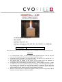
Revision-5 [2011] GEOMETRIX® - CUBE (Battery Remote Control Version) INSTALLATION MANUAL CE PIN NUMBER: 0063BQ5590 PIN: 160590 Appliance Type: B-11AS Appliance Catergories: I2H, I2E, I2E+, I2L, I3P(37), I3+, I3B/P(30) Serial Number Please quote this serial number when contacting CVO Fire regarding warranty and spare part issues. Important • • • • • It is recommended, even if you have installed these appliances before, that you take the time to read through these instructions and follow them step by step. The appliance is CE approved for use with Natural Gas – I2H, I2E, I2L, I2E+ and LPG I3P, I3+, I3B/P. Check the data plate for actual appliance setting. This manual must be handed to the owner of the property once the appliance is commissioned and retained onsite for operation and servicing reference. The appliance has a manufacturers warranty valid for 1 year from date of delivery. In order to validate the warranty the appliance must be installed by a GAS SAFE registered Engineer. The warranty card supplied with this booklet should be completed by the GAS SAFE registered Engineer and posted to : Customer Service Dept, CVO Fire. 4 Beaumont Square, Aycliffe Industrial Park, Newton Aycliffe. County Durham. DL5 6XN. Whenever contacting CVO Fire regarding the appliance please have the serial number and the installers GAS SAFE registration number available. Contents 1 Appliance Technical Data 2 Appliance General Information 3 Warning for Fire Guards and Hearths 4 Appliance Unpacking Instructions 5 Appliance Installation Instructions 6 Fit or Replace the batteries 7 Ceramics / Fuel Bed Instructions 8 Appliance Start Up / Shut Down Instructions 9 Appliance Commissioning Instructions 10 Battery Remote System 11 Battery Remote System Fault Diagnosis 12 Battery Remote System - Schematic 13 Appliance Fault Diagnosis Instructions 14 Appliance Cleaning Instructions 15 Appliance Servicing Instructions 16 Appliance Spare Parts 17 Spark Failure & Pilot System All CVO appliances are designed, manufactured and type tested to ensure they conform to the current national and European DFE (decorative fuel effect gas fire) legislation. Every CVO gas fire is fully bubble tested, adjusted and given a full function test for over 1 hour before being given a data plate and packed ready for shipping. All adjustment screws and joints are sealed. This ensures the fire leaves the factory in a fully working condition. Please read this booklet fully before starting to install the fire. If you have any queries regarding these instructions or require additional technical support or advice on the installation of our products, please contact our technical support team on 01325 327 221. The installer is to advise the user not to stand too close to the appliance for prolonged periods of time and that loose clothing is particularly at risk of burning due to the presence of an unguarded flame. 2 1. Appliance Technical Data 1.1. General Specification Oxy Pilot Assembly Marking Natural Gas Burner : SIT-9103 LPG Burner : SIT - 9272 8.0mm O.D. tubing 127.0/5.0 3.0 6.4 Gas Connection Size Minimum Flue Diameter (Millimetres/Inches) Minimum Flue Height (metres) Appliance Mass (kilograms) IT LT 9 IE 9 HU 9 GR 9 GB 9 9 9 9 9 9 9 9 9 9 9 9 9 9 9 9 9 9 9 9 9 9 9 9 9 9 9 9 9 9 9 Countries of Destination Gas Category, Type And Supply Pressure SE Sl SK TR 9 RO 9 PT PL 9 NO NL LV LU I2H - G20 at 20mbar I2E - G20 at 20mbar I2L - G25 at 25mbar I3P - G31 at 37mbar 9 9 9 9 9 9 9 9 9 I3+ - G30'G31 at 28-30'37mbar I3B/P – G30'G31 at 30mbar 9 9 Injector (1 per appliance) Marking Size Gas Category, Type And Supply Pressure I2H - G20 at 20mbar I2E - G20 at 20mbar 9 9 9 9 9 9 9 9 9 9 9 9 Nominal Heat Input kW, Gross 5.0 063 I2E+ - G20'G25at20'25mbar I2L - G25at 25mbar I3P - G31 at 37mbar Multi holed 7x0.63mm 5.0 5.0/4.6 4.6 4.0 I3+ - G30'G31 at 28-30'37mbar I3B/P – G30'G31 at 30mbar LPG 9 FR 9 NG FI 9 9 Gas Type ES 9 I3+ - G30'G31 at 28-30'37mbar I3B/P – G30'G31 at 30mbar LPG EE 9 NG DK 9 9 I2E+ - G20'G25at20'25mbar I3P - G31 at 37mbar Gas Type DE 9 CZ LPG 9 CY I2H - G20 at 20mbar I2E - G20 at 20mbar CH NG Countries of Destination BE Gas Category, Type And Supply Pressure AT Gas Type 100 Single Hole 1.0mm 4.0 4.0 Recommended maximum builders opening size – If not supplied with enclosure and gather Height, mm Width, mm Depth, mm 495 495 500 3 2. Appliance General Information The appliance is intended for decorative purposes only. The chimney should be swept before the appliance is installed, and should be swept and inspected regularly to ensure that all products of combustion are entering the flue and there is no excessive build up of soot. Foreign objects should not be placed on to the appliance or otherwise disturb the fuel bed. Debris from any source, or soot formed, should be removed from the appliance, see ‘Appliance Cleaning Instructions’. The appliance may emit a slight smell for a period of time after commissioning. This is quite normal and any odours will disperse within a few hours of operation. The pilot light and flame sensing device installed to the appliance are also atmospheric sensing devices. The device is not adjustable and must not be disabled. If evacuation of combustible products is interrupted the device shuts down both the main burner and pilot light. In the event of a single shut down, do not attempt to re-light the pilot within three minutes, once three minutes have passed the appliance can be re-started in accordance with ‘Appliance Start Up / Shut Down Instructions’. In the event of repeated shut downs, do not use the appliance and have the flue and appliance checked by a GAS SAFE Engineer. If any part of the pilot assembly needs to be replaced, including the pilot burner, thermocouple, electrode and injector the complete assembly must be replaced with an original manufacturer's pilot assembly by a GAS SAFE Engineer. Warning – Do not adjust the system. Warning – Do not disable the flame sensing device. Warning – Use only OEM parts. The installation should only be carried out by a GAS SAFE Engineer and in accordance with national and local regulations for gas. The installation must also be in accordance with relevant parts of local and national building regulations. For the Republic of Ireland, reference should be made to IS813 and ICP3 and any guidance notes from Bord Gais. Read the instructions carefully before proceeding. Failure to do so could result in an unsafe installation and may invalidate the warranty. 3. Warning for Fire Guards and Hearths The appliance is not installed with an integral guard. In normal use consideration may be given to the use of a fireguard conforming to BS6539 or BS6778, so that the approach to the appliance is limited such that access to the flame is minimised. It is recommended that a fireguard conforming to the requirements of BS6539 or BS6778 be installed if the appliance is used in the presence of young children, the elderly or the infirm. For some countries a non-combustible hearth must be installed in front of the appliance in accordance with national regulations (e.g. United Kingdom). In addition, the installer is to advise the user against placing combustible material directly in front of the appliance. 4 4. Appliance Unpacking Instructions Carefully examine the carton for damage before unpacking. If the appliance is damaged, consult your supplier over whether to proceed. Extreme care should be used when handling the ceramic fuel bed (if supplied) as this can be easily damaged. Remove the appliance and examine its general condition. If satisfied by the condition of the product, proceed with the installation. 5. Appliance Installation Instructions (Appliance is to be installed by a GAS SAFE Registered Engineer only!) 5.1. General Clearances between the appliance and all combustible materials must conform to national regulations. The appliance must be installed and used in accordance with these instructions. Prior to installation, ensure that the local distribution conditions (identification of the type of gas and pressure and the adjustment of the appliance) are compatible. The builders opening or fireplace opening must be constructed of a non-combustible material. Any flue damper plate or flue restrictor must be removed or fixed permanently in a fully open position, or shall only be installed in accordance with national regulations. The chimney must be swept before the appliance is installed. If the chimney is not swept, there is a possibility that loose debris may fall onto the burner unit which may result in damage and unnecessary service costs. Before the appliance is installed a flue test in accordance with national regulations should be carried out. The appliance must not be installed unless the chimney or flue length is at least the length and size indicated in the section marked ‘Appliance Technical Data’ earlier in this manual. Under no circumstances should the appliance be installed and operated within any premises without an adequate flue or chimney system. An air supply must be installed in accordance with national regulations and should be checked regularly to ensure that it is free from obstruction. Soundness of the input gas line should be checked prior to installing the appliance. If the gas line has been left open then any debris must be removed. The gas connection must be made in accordance with national regulations. An isolation valve (stop tap) must to be installed adjacent to the appliance, which when closed allows the complete burner and control assemblies to be disconnected for maintenance and repair in accordance with national regulations. 5 5.2. Fixing the Base Unit The appliance is supplied with a base plate. This must be installed to a flat, level surface using the two fixing points shown below. When using the standard CVO Fire Enclosure pilot holes are given to ensure correct positioning of the burner. If not installing in a CVO supplied enclosure please refer to the required opening sizes and burner positioning as shown on Page 3. The main unit is then attached to the base using four screws, as shown below. This will create a “floating” look as the main body is raised from the base by 15mm. 6 6. Fit the Batteries The fire has a remote control system operated by AA batteries. It is advised to use high quality lithium batteries as they will have a long life. When first supplied the batteries need to be connected. To fit or replace the batteries. • • • • • • An Allen key is supplied with the fire. This MUST be given to the owner of the property once the fire is installed. Use the Allen key to unscrew the cover screw. Open the battery cover Add the batteries noting the correct way round. Once the batteries are fitted, replace the cover. Save the Allen key. 7 7. Positioning of Fuel Bed / Ceramics Note: The Natural Gas (NG) version of the burner can be purchased with or without ceramics. The LPG version can only be purchased with ceramics and must only be used with the ceramics in place. If ceramics have been supplied with the fire they should be positioned as shown in the diagrams below. If the ceramics become damaged a new set should be ordered. The burner fuel bed options are shown below: CERAMAT MATTING (Natural Gas [NG] Version Only) This special ceramic matting creates a unique flame quality which sparkles across the top of the surface. If the matting is damaged the fire should not be used and the fire returned to the manufacturer for repair of the matting surface. Damage to the matting is not covered by the warranty. Shown above is the fire with matting only. Great care should be observed when handling the fire to ensure the matting does not become damaged. 8 PEBBLE SET The Pebble set should be positioned on the ceramic matting taking great care not to damage the surface. The set includes: 1 x Large Inner Ring, 4 x Medium size pebbles, 1 x Small size pebble. Use the instruction below to fit the pebbles. Procedure Image STEP-1 Place the first ring in the centre of the matting ensuring that the matting surface is not damaged. Note that the flat base must be down. The top has grooves for positioning the upper pebbles. See image right for positioning. STEP-2 The inner ring has grooves in the top surface. There are 4 medium sized pebbles which are marked (MV) on the base. Position each pebble with the flat base down in the grooves on the lower ring in step 1. See image right for positioning. STEP-3 Place the final small pebble on top of the pile. See image right for positioning. 9 TWIG SET The Twig set should be positioned on the ceramic matting taking great care not to damage the surface of the matting; Great care must be taken in handling the twigs as they are fragile. The set includes 7 pieces. Procedure Image STEP-1 Place the twig block in the centre of the matting ensuring that the matting surface is not damaged. Note that the flat base must be down. The top has grooves for positioning the upper twigs. See image right for positioning. STEP-2 Using the grooves in the top of the twig block fitted in step 1 as a guide fit the 4 smaller “Y” shaped twigs. The longer leg of the “Y” should be in the corner of the matting. See image right for positioning. STEP-3 Place the 2 remaining twigs around the “Y” shaped twigs so they meet in the centre. See image right for positioning. 10 8. Appliance Start Up / Shut Down Instructions The appliance is controlled by a Battery Remote system powered by AA Batteries. WARNING: If the main burner or pilot light is extinguished during lighting, do not attempt to re-light the pilot within three minutes. There are two methods of lighting the appliance – Hand Set Infra Red and Manual Switch on the right hand side of the enclosure. 8.1 - Using the Manual Control Panel (see image). • Button #1 - By pressing this switch, this starts the ignition sequence (press & hold for 3 sec minimum). The gas to the pilot is open and the magnet unit pressed by the motor, the spark is generated. When the pilot flame presence is detected (ionization flame control) the system holds for 10 seconds to warm the thermocouple. • Once the thermocouple is warm enough to hold the magnet unit the valve will allow gas to the burner at the maximum setting. • In case of failure during pilot ignition sequence, the EDB puts the system in safe mode. To restart the ignition sequence press Button #1 again. • It is possible once the fire is lit to operate in standby mode with pilot only lit. To do this press button #2. • By pressing Button #3 the burner flame is increased to the maximum rate. • By pressing Button #4 the burner flame can be reduced to the minimum rate. • By pressing Button #3 (increase) or Button #4 (decrease) the power output of the appliance can be set between maximum and minimum levels. • To turn the appliance OFF Button #1 is pressed. • Each time a button is pressed a “beep” will be heard. 11 8.2 - Using the Remote Control Handset (see image) • The operation sequence is the same as stated in the section apart from the ON setting. As a child proof system both buttons #1 & #2 must be pressed at the same time. To operate correctly the handset must be pointed directly at the magic eye on the front of the cube. (see image) • To Summarise: o Button #1 & Button #2 together – This switches the appliance ON. • o Button #1 – This switches the appliance OFF. o Button #2 – This sets the unit into standby mode (pilot only) o Button #3 – This sets the flame at maximum rate. o Button #4 – This sets the flame at minimum rate. Each time a button is pressed a “beep” will be heard. NOTE: If the appliance is shut down unexpectedly the valve must be reset first before the fire can be re-lit. To do this press the “OFF” button until a beep is heard. Then commence the starting sequence as detailed above by pressing both left had buttons at the same time. 12 9. Appliance Commissioning Instructions 1. The burner inlet flow rates are factory set and sealed. Under no circumstances should these settings be changed. 2. The appliance is supplied with a pressure test elbow and gas tap. Connect an 8mm gas supply to the isolation tap. Connect a Manometer to the test point and check the gas line standing pressure is within the required limits of +/- 1mBar of the inlet pressure on the data plate within the appliance. 3. Check the gas line for soundness. 4. Light the appliance using the handset or switch on the side of the appliance. 5. TEST #1 : Once lit turn the appliance onto the full setting and read the manometer connected to the inlet test point elbow. The inlet supply pressure must be within (+/- 1mb) of the pressure stated on the Data Plate. For example Natural Gas should be 21mBar to 19mBar. 6. TEST #2 : Light all other gas appliances in the house, including central heating systems and check the inlet pressure again. The pressure must still be within the tolerance of +/- 1mb. 7. TEST # 3: Now turn off all the other gas appliances and turn the appliance down to pilot only, the pressure must still be in the tolerance of +/- 1mb. 8. IF FAILED: If it is not possible to maintain the pressure at the required level, TRANSCO, BORD GAIS or the propane supplier must be called to adjust the governor to the house before the appliance can be commissioned further. 9. IF PASSED: Disconnect the pressure gauge, replace the pressure test point sealing screw and test the appliance for gas soundness. 10. FLUE TEST: Light the appliance and set on maximum setting. Leave the appliance for 10 minutes and then test that all the products of combustion are entering the flue by traversing the perimeter of the fireplace opening or canopy using a smoke generator e.g. smoke matches. 13 IF PASSED: a. The customer should be shown in detail how to operate the appliance and the installation manual given to the customer. b. The warranty card must be completed and given to the customer. c. The customer must also be aware that the appliance must be serviced every 12 months and that chimney or flue system should be checked regularly to ensure the appliance operates at optimum performance. d. The installation booklet and fitting kit must be given to the customer. If you have any questions, or the appliance is not operating correctly, please consult the fault diagnosis chart and then contact the CVO Fire technical team BEFORE you leave the installation. As part of our customer service procedure you will be asked for the appliance serial number on the front cover of this booklet and the GAS SAFE Registration number of the Engineer. If the appliance is not installed in strict accordance with these instructions CVO Fire cannot be held responsible for any damage caused and reserve the right to charge for any corrective work. The warranty covers defective components or manufacture not incorrect installation or site specific conditions. 10. Battery Remote System Note: The burner has 6 x AA batteries built into the side. The handset requires 2 x AA batteries. This gas fire is operated via a battery remote system. Operation is via a handset (with Infra Red magic eye position on the front of the appliance) or a manual switch plate on the side of the appliance. In the event that the fire will not operate it should be assumed that the batteries have become extinguished. WARNING: The appliance must be switched off before changing the batteries. WARNING: The appliance must be allowed to cool down for a minimum of 2 hours before starting to change the battery. 14 11. Battery Remote System – Alarm Sequence This fire is operated via a battery remote system with AA batteries. The remote system has a built in alarm system which indicates and faults which may arise. A fault is indicated by a sequence of a predefined “beeps”. The number of beeps corresponds to a certain failure. NOTE: There are two types of black box fitted to this type of appliance. See the black box to identify which one is fitted to your fire. BLACK BOX – EDB20 Alarm sound description 2 x Beeps = Low battery alarm. In case of low battery voltage (supply voltage below 6V) the buzzer produces a sequence of 2 beeps with a repetition rate of 1s. To resume the normal operation it’s necessary to recharge or substitute the battery with a new one and to verify the alarm sound is no more present. 3 x Beeps = Manual Wall Keyboard failure sound. In case of keyboard failure (i.e. cable opens or pushbutton stuck closed) the buzzer produces a sequence of 3 beeps with a repetition rate of 1s. To resume the normal operations it’s necessary to substitute the keyboard with a working one and to verify the alarm sound is no more present. 4 x Beeps = Motor Failure sound. In case of motor failure, the buzzer produces a sequence of 4 beeps with a repetition rate of 1s. To resume the normal operations it’s necessary to substitute the valve with a working one, to repeat the ignition sequence and to verify the alarm sound is no more present. 5 x Beeps = Driver leakage sound. In case of on board motor driver current leakage failure the buzzer produces a sequence of 5 beeps with a repetition rate of 1s. To resume the normal operation it’s necessary to substitute the board with a working one, to repeat the ignition sequence and to verify the alarm sound is no more present. 6 x Beeps = Under voltage low battery. In case on under voltage low battery (supply voltage less than ADC circuit reference power supply); the buzzer produces a sequence of 6 beeps with a repetition rate of 1s. To resume the 15 normal operations it’s necessary to substitute the battery with a new one and to verify the alarm sound is no more present. BLACK BOX – IR/RF Alarm sound description 7 x beeps – Low Battery Substitute the battery with a new one and verify the sound alarm stops. Before inserting the new battery pack, remove the old one and wait until the sound disappears. Wait at least 2 minutes before adding the new batteries. If the sound is still present after adding new batteries, execute an ignition sequence. 3 x beeps – Manual Wall Switch Keyboard Failure Substitute the keyboard with another one and verify the sound alarm stops. 4 x beeps – Valve Motor Failure Substitute the valve with another one. Repeat the ignition sequence and verify the sound alarm stops. 5 x beeps – Driver Leakage [Black Box Faulty] Substitute the board: the motor drive circuit is damaged. Execute an ignition sequence and verify there’s no sound alarm. 6 x beeps – Under Voltage Low battery Substitute the battery with a new one and verify the sound alarm stops. Before inserting the new battery pack, remove the old one and wait until the sound disappears. Wait at least 2 minutes before adding the new batteries. If the sound is still present after adding new batteries, execute an ignition sequence. Battery Replacement: When replacing the batteries they must be replaced as a complete set and a full new set used. The system has a memory and if any old batteries are used the alarm sequence will not be reset. To reset the alarm: Remove the old batteries. Wait 10 minutes. Fit a set of 6 new Alkaline or Lithium batteries. Start the fire. 16 12. Battery Remote System – Schematic Schematic of Battery Remote System. All parts are required to ensure system operates safely and efficiently. To order replacement parts please call 01325-327221 and ask for customer service department. 17 13. Appliance Fault Diagnosis Instructions This appliance has a battery remote system with rechargeable batteries inside the appliance. The Handset also requires batteries. Please ensure that the batteries are fully charged and in good condition prior to operating this appliance. Please use the fault diagnosis tick sheets to resolve any issues which may arise. Symptom Fire will not light with handset or manual switch. Appliance will light using manual switch but not with the remote handset. Appliance will light using the handset but not with the manual switch. Appliance clicks but no spark or weak spark. Appliance sparks but does not light pilot. If there is no gas. Check List Tick Check main batteries are not flat – change if required. Consult Battery Remote Fault Diagnosis – section 10. Check that there is a spark and gas present at the pilot using a match. Ensure that the handset is aiming directly at the magic eye (line of sight) and is within normally operation distance (2 meters) Ensure the handset batteries are fully charged. Check operation sequence as detailed in section 8 The handset may have become damaged - Order new handset. Check operation sequence as detailed in section 8 Change the main AA batteries within the unit. Check spark lead is connected properly. Check spark electrode is in the correct area and the gap correctly distanced to the pilot. Check for a good spark. Check the spark is in the right area. Check that the ventilation is not too strong and drawing the gas away from the pilot. Check that there is gas at the input and at the pilot. Check that manual valve is operated correctly. Check isolation tap/shut off is open. Check for blockages in the gas pipes. Check for a good spark. If there is gas but pilot does not light Check the spark is in the right area. Check that the ventilation is not too strong and drawing the gas away from the pilot. Check the pilot gas slot is clear. Check the pilot flame is heating the thermocouple. Pilot lights but does not light main burner Check the thermocouple nut is properly tightened into the valve. Check that the pilot lights early on ignition clicks. Check ventilation is not too strong and drawing the pilot flame away from the thermocouple. When using LPG Bottles ensure bottle is not empty. Burner lights but turns off after a few minutes Check thermocouple nut is properly secured to the valve. Check ventilation is not too strong and the flame is not blowing off the thermocouple. Check gas pressure is correct and maintained at constant level – especially with other appliances in the home working. 18 14. Appliance Cleaning Instructions Before any cleaning, ensure the appliance is switched off and has been given time to cool down. Matting :Due to the surface area and flatness of the ceramic burner matting, it is inevitable that dust, debris from the chimney and combustion by-products will accumulate, consequently the surface area of the burner unit should be cleaned at regular intervals. The most effective method of dust/debris removal is achieved with the aid of a vacuum cleaner however, great care must be taken to ensure that there is no contact between the cleaner and the surface area of the burner unit, as damage to the matting will result in the complete replacement of the matting panel. The replacement can only take place in the factory. After ensuring that no damage has been done to the surface the appliance is ready to re-ignite. Burner Shell :The Outer shell of the burner can be cleaned with a soft cloth with stainless steel cleaner. Always move in the direction of the grain of the steel. Ensure no cleaning materials come in contact with the matting surface as damage may occur. 15. Appliance Servicing Instructions CVO Fire recommends that the appliance is serviced every 12 months by a GAS SAFE Engineer. Step 1: Turn off the appliance and allow it to cool. Step 2: Turn off the gas supply stop tap. Step 3: Turn off the appliance stop tap. Step 4: Disconnect the gas inlet pipe from appliance stop tap. Step 5: Remove the four base assembly screws. Step 6: Remove the main unit from the base taking care not to damage the burner matting. Step 7: Remove the venturi cover screw and venturi cover (natural gas only), then remove and clean the injector. Do not use a tool that could damage the injector. Step 8: Re-assemble in the reverse order, reconnect the gas supply. Step 9: Using a soft brush or vacuum cleaner remove any debris from the top surface of the appliance. Step 10: Check for gas soundness. Step 11: Check that any purpose provided ventilation is free from obstruction. Step 12: Re-commission the appliance as described in ‘Appliance Commissioning Instructions’. 19 16. Appliance Spare Parts There are no user serviceable parts on the appliance. Spare parts which are available to order from the Customer Service Department for replacement by a GAS SAFE Engineer only are :1. 2. 3. 4. 5. 6. 7. 8. Remote Valve Remote Black Box Ignition Cable Remote Handset IR Magic Eye Manual Switch Gas Injector for Natural Gas or LPG/Propane Pilot Assembly for Natural Gas or LPG/Propane NOTE: CERAMIC MATTING Under normal use the matting will have a very long life. The matting can be easily damaged by touching or cleaning. If the ceramic matting becomes damaged the appliance should not be used. The matting can only be replaced by returning the appliance to the factory. This damage is not covered by the warranty and will be charged at current rate. To make arrangements for the return and repair of the appliance please call 01325-301020. To order spare parts please contact: CVO Fire Customer Service on 01325 327221 17. PILOT ASSEMBLY The pilot is a safety device and must never be tampered with or disabled. If the chimney becomes blocked the pilot will shut the fire down. T will also shut the fire down if the gas pressure is incorrect. If the fire shuts down suddenly consult a Gas Engineer to check the gas pressure and flue system. 20 ONLY USE GENUINE REPLACEMENT PARTS. The information supplied in this manual is correct at the time of publish; Dated on the 28-2-2011 There may be changes made in future as we improve our products. If there are any queries please write to or call our technical department. The CVO Fire brand is owned and manufactured by: Spirit Fires Ltd, 4 Beaumont Square Aycliffe Industrial Park, Newton Aycliffe County Durham, DL5 6SW T – 01325 327 221 F – 01325 327 292 Email – [email protected] Web – www.cvo.co.uk 21 GEOMETRIX™ - CUBE [Remote Version] USER MANUAL CE PIN NUMBER: 0558BQ5590 / PIN: 160590 Serial Number Please quote this serial number when contacting CVO Fire. Important • • • This manual must be handed to the owner of the property once the appliance is commissioned and retained onsite for operational reference. The appliance has a manufacturers warranty valid for 1 year from date of delivery. In order to validate the warranty the appliance must be installed by a GAS SAFE Engineer. The warranty card supplied with this booklet should be completed by the GAS SAFE Engineer and posted to : Customer Service Dept, CVO Fire. 4 Beaumont Square, Aycliffe Industrial Park, Newton Aycliffe. County Durham. DL5 6XN. Whenever contacting CVO Fire regarding the appliance please have the serial number and the installers GAS SAFE registration number available. Contents 1 Appliance General Information 2 Warning for Fire Guards and Hearths 3 Appliance Unpacking Instructions 4 Appliance Installation Procedure 5 Appliance Start Up / Shut Down Instructions 6 Battery Remote System – Changing the Main Batteries 7 Appliance Cleaning Instructions 8 Appliance Servicing Instructions 9 Appliance Spare Parts Every appliance has been designed, manufactured and type tested to ensure that it conforms to the current national and European DFE (decorative fuel effect gas fire) legislation. If you have any queries regarding these instructions or require additional technical support or advice on the installation of our products, please contact the technical support team on 01325 327 221. Do not to stand too close to the appliance for prolonged periods of time. Loose clothing is particularly at risk of burning due to the presence of an unguarded flame. 2 1. Appliance General Information The appliance is intended for decorative purposes only. The chimney should be swept and inspected regularly to ensure that all products of combustion are entering the flue and there is no excessive build up of soot. Foreign objects should not be placed on to the appliance or otherwise disturb the fuel bed. Debris from any source, or soot formed, should be removed from the appliance, see ‘Appliance Cleaning Instructions’. The appliance may emit a slight smell for a period of time after commissioning. This is quite normal and any odours will disperse within a few hours of operation. The pilot light and flame sensing device installed to the appliance are also atmospheric sensing devices. The device is not adjustable and must not be disabled. If evacuation of combustible products is interrupted the device shuts down both the main burner and pilot light. In the event of a single shut down, do not attempt to re-light the pilot within three minutes, once three minutes have passed the appliance can be re-started in accordance with ‘Appliance Start Up / Shut Down Instructions’. In the event of repeated shut downs, do not use the appliance and have the flue and appliance checked by a GAS SAFE Engineer. If any part of the pilot assembly needs to be replaced, including the pilot burner, thermocouple, electrode and injector the complete assembly must be replaced with an original manufacturer's pilot assembly by a GAS SAFE Engineer. Warning – Do not adjust the system. Warning – Do not disable the flame sensing device. Warning – Use only OEM parts. The installation should only be carried out by a GAS SAFE Engineer and in accordance with national and local regulations for gas. The installation must also be in accordance with relevant parts of local and national building regulations. For the Republic of Ireland, reference should be made to IS813 and ICP3 and any guidance notes from Bord Gais. 3. Warning for Fire Guards and Hearths The appliance is not installed with an integral guard. In normal use consideration may be given to the use of a fireguard conforming to BS6539 or BS6778, so that the approach to the appliance is limited such that access to the flame is minimised. It is recommended that a fireguard conforming to the requirements of BS6539 or BS6778 be installed if the appliance is used in the presence of young children, the elderly or the infirm. For some countries a non-combustible hearth must be installed in front of the appliance in accordance with national regulations. 2. Appliance Unpacking Instructions Carefully examine the carton for damage before unpacking. If the appliance is damaged, consult your supplier over whether to proceed. Remove the appliance and examine its general condition. If satisfied with the condition of the product, allow the GAS SAFE Engineer to proceed with the installation. 3 4. Appliance Installation Procedure (For User Reference Only) Clearances between the appliance and all combustible materials must conform to national regulations. The appliance must be installed and used in accordance with these instructions. Prior to installation, ensure that the local distribution conditions (identification of the type of gas and pressure and the adjustment of the appliance) are compatible. The builders opening or fireplace opening must be constructed of a non-combustible material. Any flue damper plate or flue restrictor must be removed or fixed permanently in a fully open position, or shall only be installed in accordance with national regulations. The chimney must be swept before the appliance is installed. If the chimney is not swept, there is a possibility that loose debris will fall onto the burner unit which will result in damage and unnecessary service costs. Before the appliance is installed a flue test in accordance with national regulations should be carried out. The appliance must not be installed unless the chimney or flue length is at least the length and size indicated in the section marked ‘Appliance Technical Data’ in the Installation Manual. Under no circumstances should the appliance be installed and operated within any premises without an adequate flue or chimney system. An air supply must be installed in accordance with national regulations and should be checked regularly to ensure that it is free from obstruction. Soundness of the input gas line should be checked prior to installing the appliance. The gas connection must be made in accordance with national regulations. An isolation valve (stop tap) must to be installed adjacent to the appliance, which, when closed allows the complete burner and control assemblies to be disconnected for maintenance and repair in accordance with national regulations. 4 5. . Appliance Start Up / Shut Down Instructions The appliance is controlled by a Battery Remote system powered by AA Batteries. WARNING: If the main burner or pilot light is extinguished during lighting, do not attempt to re-light the pilot within three minutes. There are two methods of lighting the appliance – Hand Set Infra Red and Manual Switch on the right hand side of the enclosure. 8.1 - Using the Manual Control Panel (see image). • Button #1 - By pressing this switch, this starts the ignition sequence (press & hold for 3 sec minimum). The gas to the pilot is open and the magnet unit pressed by the motor, the spark is generated. When the pilot flame presence is detected (ionization flame control) the system holds for 10 seconds to warm the thermocouple. • Once the thermocouple is warm enough to hold the magnet unit the valve will allow gas to the burner at the maximum setting. • In case of failure during pilot ignition sequence, the EDB puts the system in safe mode. To restart the ignition sequence press Button #1 again. • It is possible once the fire is lit to operate in standby mode with pilot only lit. To do this press button #2. • By pressing Button #3 the burner flame is increased to the maximum rate. • By pressing Button #4 the burner flame can be reduced to the minimum rate. • By pressing Button #3 (increase) or Button #4 (decrease) the power output of the appliance can be set between maximum and minimum levels. • To turn the appliance OFF Button #1 is pressed. • Each time a button is pressed a “beep” will be heard. 5 8.2 - Using the Remote Control Handset (see image) • The operation sequence is the same as stated in the section apart from the ON setting. As a child proof system both buttons #1 & #2 must be pressed at the same time. To operate correctly the handset must be pointed directly at the magic eye on the front of the cube. (see image) • To Summarise: o Button #1 & Button #2 together – This switches the appliance ON. • o Button #1 – This switches the appliance OFF. o Button #2 – This sets the unit into standby mode (pilot only) o Button #3 – This sets the flame at maximum rate. o Button #4 – This sets the flame at minimum rate. Each time a button is pressed a “beep” will be heard. NOTE: If the appliance is shut down unexpectedly the valve must be reset first before the fire can be re-lit. To do this press the “OFF” button until a beep is heard. Then commence the starting sequence as detailed above by pressing both left had buttons at the same time. 6 6. Battery Remote System – Changing the Batteries GAS FIRE BATTERIES This gas fire is operated via a battery remote system with AA Batteries. Operation is via a handset (with Infra Red magic eye position on the front of the appliance) or a manual switch plate on the side of the appliance. In the event that the fire will not operate it should be assumed that the batteries have become extinguished. WARNING: The appliance must be switched off before changing the battery. WARNING: The appliance must be allowed to cool down for a minimum of 2 hours before starting to change the battery. HAND SET BATTERIES The handset requires 1 x 9V battery which is available from most supermarkets or hardware stores. It is advised to use good quality batteries. If the hand set batteries need replacement. Remove the handset cover. Remove old batteries and insert new batteries. The main fir body has a remote control system operated by “AA” batteries. It is advised to use high quality lithium batteries as they will have a long life. To fit or replace the main batteries. • • • • • • An Allen key is supplied with the fire. Use the Allen key to unscrew the cover screw. Open the battery cover Add the batteries noting the correct way round. Once the batteries are fitted, replace the cover. Save the Allen key. 7 7. Appliance Cleaning Instructions Before any cleaning, ensure the appliance is switched off and has been given time to cool down. Matting :Due to the surface area and flatness of the ceramic burner matting, it is inevitable that dust, debris from the chimney and combustion by-products will accumulate, consequently the surface area of the burner unit should be cleaned at regular intervals. The most effective method of dust/debris removal is achieved with the aid of a vacuum cleaner however, great care must be taken to ensure that there is no contact between the cleaner and the surface area of the burner unit, as damage to the matting will result in the complete replacement of the matting panel. The replacement can only take place in the factory. After ensuring that no damage has been done to the surface the appliance is ready to re-ignite when ready. Burner Shell :The Outer shell of the burner can be cleaned with a soft cloth with stainless steel cleaner. Always move in the direction of the grain of the steel. Ensure no cleaning materials come in contact with the matting surface as damage may occur. 8. Appliance Servicing Instructions CVO Fire recommends that the appliance is serviced every 12 months by a GAS SAFE Engineer. 9. Appliance Spare Parts There are no user serviceable parts on the appliance. 8 The information supplied in this manual is correct at the time of publish; Dated on the 28-2-2011. There may be changes made in future as we improve our products. If there are any queries please write to or call our technical department. The CVO Fire brand is owned and manufactured by: Spirit Fires Ltd, 4 Beaumont Square Aycliffe Industrial Park, Newton Aycliffe County Durham, DL5 6SW T – 01325 327 221 F – 01325 327 292 Email – [email protected] Web – www.cvo.co.uk 9