1
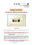
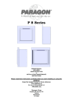
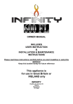
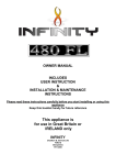
Rev-2 FR600 (with Manual Control) HIGH EFFICIENCY WALL MOUNTED GAS FIRE APPROVAL : BS7977-1:2009 TECHNICAL INSTALLATION MANUAL The FR600 gas fire is available for Natural Gas (G20) only at a supply pressure of 20mbar. Serial Number ……………………………… Please quote this serial number when making a claim. Your Warranty is valid for 1 Year from date of delivery. The Warranty card supplied is to be filled in and sent to Spirit Fires Limited. 4 Beaumont Square, Aycliffe Industrial Park, Newton Aycliffe, County Durham, DL5 6XN The Instructions for Installation and Maintenance plus User Instructions must be handed to the User once the Appliance is Commissioned and retained for future reference. Page 1 of 38 Contents Page Page Page Page Page Page Page Page Page Page Page Page 3 5 6 6 6 7 8 8 9 12 12 14 Page Page Page Page Page Page Page Page Page Page Page Page 16 17 18 18 18 19 20 21 22 24 25 27 Introduction and Installation Requirements Appliance Efficiency Declaration Unpacking the Appliance Parts List Technical Data FR600 Dimensions Gas Burner Construction Restrictor Plate Building and Installation Work Connect the Gas Supply Fitting the Ceramic Pebbles Commissioning the Fire Check Gas Pressure Check for Spillage Fitting the Fascia Commissioning Checklist Oxygen Depletion Pilot System Spark Failure Warning Fire Guards and Hearths Exchangeable Parts Removing and Cleaning the Glass Panel Burner Removal Replacing Components Service and Aftercare Requirements Fault Diagnosis/Troubleshooting Gas Fire User Instructions Page 2 of 38 Introduction & Installation Requirements. Consumer Protection Information As the manufacturer and supplier of heat products, we take every care, as far as is reasonably practicable, that these products are so designed and constructed as to meet the general safety requirement when properly used and installed. To this end, our products are thoroughly tested and examined before dispatch. IMPORTANT NOTICE: Any alteration that is not approved by the appliance manufacturer could invalidate the approval of the appliance, operation of the warranty and could affect your statutory rights. Health and Safety Notice Important: This appliance could contain some of the materials, indicated below, that could be interpreted as being injurious to health and safety. It is the user’s / installer’s responsibility to ensure that the necessary personal protective clothing is worn when handling these materials, see below for information. Artificial Fuels, Mineral Wool, Insulation Material, Refractory/Ceramic Fibres, Glass Yarn – may be harmful inhaled, may be irritating to skin, eyes, nose and throat. When handling avoid inhaling and contact with skin or eyes. Use disposable gloves, facemasks and eye protection. After handling wash hands and other exposed parts. If a vacuum is used for cleaning the coals or cleaning after servicing / installation it is recommended that it be of the type fitted with a HEPA filter. • • • • • • • • • The FR600 has been designed and tested to the requirements of BS79771:2009 and is suitable for use in GB (Great Britain) and IE (Ireland). The FR600 is a High Efficiency wall mounted gas fire for use with a chimney or flue system. The FR600 incorporates a single gas control, which has a Piezo ignition pilot, with variable setting between low and high settings. Like all appliances incorporating an aerated burner a low frequency noise may be heard, this may be more noticeable on the low setting. The FR600 incorporates a safety device in the form of an Oxygen Depletion System, which constantly monitors the oxygen in the room and will cause the fire to switch off if the oxygen level reduces, for instance due to a blocked flue. If this regularly occurs do not attempt to relight the appliance until a qualified engineer has checked it. The installation must be carried out by a Gas Safe registered engineer in accordance with National Regulations. Clearances between the fire and all combustible materials must conform to National Regulations. This appliance is supplied as a complete fireplace package including gas fire burner unit, enclosure and fascia. This fire must be installed and used in accordance with these instructions. The builders opening or fireplace opening must be constructed of a noncombustible material. Page 3 of 38 • • • • • • • • • • For some countries a non-combustible hearth must be fitted in front of the fire in accordance with National Regulations (e.g. United Kingdom). Flue System: The FR600 can be used with a brick built chimney or a lined flue with a minimum diameter of 125mm (5”). The chimney must have a minimum effective height of at least 3 metres. The chimney should be swept prior to installation if it has previously been used with solid fuel. This is not necessary if the flue has previously been used with a gas appliance or if it is a new installation. (see install section for full details on the flue requirements). Any flue damper plate or flue restrictor must be removed. Gas Supply: The appliance is for use on Natural Gas (G20 @ 20mbar) only. Inlet is via an 8mm gas line to the isolation valve provided with the fire. The gas connections must be in accordance with National Regulations. If the gas line is longer than 1.5mtrs then the gas line should be increased in diameter to 15mm and possibly larger depending on the final length to ensure a steady gas supply. The fire is supplied with an isolation valve inside the appliance. This must be used. When closed this will allow the complete burner and control assembly to be disconnected for maintenance or repair in accordance with National Regulations. The pilot light and flame sensing device fitted to this fire is also an atmosphere sensing devise. If for any reason any part of the pilot assembly is to be replaced ALL the assembly including the pilot burner, thermocouple, electrode and injector must be exchanged complete for an original manufacturer’s pilot assembly only. This atmosphere sensing devise is not adjustable and must not be put out of action. The pilot light shuts off both the main burner and pilot if evacuation of the combustion products is interrupted. If the fire shuts itself off, do not use the fire, and have the flue and fire checked by a suitably qualified person. The FR600 is operated by a manual control valve with piezo ignition therefore no mains electrical supply is required. Please take some time to learn the lighting procedure. The chimney or flue (unless new or previously used with a gas appliance) must be swept before installation if it has been used for solid fuel. The fire front (fret) or fascia supplied must be used with this appliance. The fascia must be installed with the fascia “floating” on the wall. Failure to install the appliance correctly could lead to prosecution. In GB (Great Britain), the appliance must be installed by a competent person i.e. GAS SAFE registered, in accordance with the GAS SAFETY (INSTALLATION AND USE) REGULATIONS, the building regulations (or the building regulations (Scotland) or the building regulations (Northern Ireland). In IE (Ireland), the appliance must be installed by a competent person and installed in accordance with the current edition of I.S.813 Domestic Gas Installation, the current building regulations. The glass front of this fire acts as a dress guard, conforming to BS 1945 (1997) however, a fireguard conforming to BS6539 (1997) must be used to protect young children, the elderly or infirm. The appliance MUST NOT be used with the glass safety screen removed or if it is damaged or cracked. Page 4 of 38 • • • • • • • During initial usage, an odour may be evident. This is the starch binder used during the manufacture of the fibre components of the fire, and there are no harmful effects produced. During the normal operation of the fire some staining may appear on some parts of the fire burner. This is quite normal due to the heat generated by the appliance. During initial starting of the appliance condensation may be seen on the glass and the flame may be unstable. This is normal with this type of appliance and will disappear when the fire and flue system are warm. This is a high efficiency gas fire and generates a considerable amount of heat from the top of the appliance. Care must be taken to prevent any damage being caused to surrounding soft furnishing or decoration, e.g. many embossed vinyl wall coverings may become discoloured if placed too close to the appliance. Combustible material i.e. wall panelling or wallpaper must be removed from behind the fire and fire trim. It is advised that this appliance is serviced annually, as it is more likely to provide trouble-free operation. The fire does not require purpose built permanent ventilation as it conforms to BS 5871-2: 2005 +A1: 2007 – Annex B (has a net heat input of ≤7kW and a flue flow of ≤70m3/h This appliance becomes hot during operation therefore all areas must be considered to be working surfaces. Appliance Efficiency Declaration EFFICIENCY CLASS – 1 GROSS EFFICIENCY – 74.5% NOx CLASS - 4 The efficiency of this appliance has been measured as specified in: BS7977-1:2009 - Specification for safety and rational use of energy of domestic gas appliances – Radiant/Convectors. The Gross calorific value of the fuel has been used for this efficiency calculation. The test data from which it has been calculated has been certified by Gastec at CRE Limited [notified body number 0558]. The efficiency value may be used in the UK Government’s Standard Assessment Procedure (SAP) for energy ranging of dwellings Page 5 of 38 Unpacking the Appliance Read these instructions fully before starting to install the fire. Carefully examine the carton for damage before proceeding. If it is obviously damaged, please contact the supplier over whether to proceed. Remove the fire and examine its general condition. If satisfied by the condition, proceed with the installation. PLEASE NOTE no claims will be accepted for damaged or faulty components once the appliance has been installed. Parts List • Fire is supplied as a complete unit with: o Gas Fire Body. o Steel Fascia. o Ceramic Set. o Installation Booklet. o Fitting Kit. Technical data Pilot Assembly Marking SEAGAS P4-37D AC060 stamped “220” Injector Gas connection 8mm O.D. tube Minimum flue diameter 125.0mm Minimum flue height* 3.0m Room Ventilation Not Required Approximate weight Gas Type Gas Pressure Nominal Heat Input 10kg G20 – I2H – Natural Gas 20mBar 3.7 kW, Gross Nox level Class 4 Efficiency Class 1 Efficiency Rating [NET] 82.8% Efficiency Rating [Gross] SAP 74.5% *WARNING: THIS FIRE IS NOT AVAILABLE FOR LPG. Page 6 of 38 FR600 Dimensions Page 7 of 38 Gas Burner Construction Take some time to review the burner construction taking note of the positions of the main components and the required connections. Before starting to install the appliance review the Data Plate fitted to the appliance for the gas type and pressure requirements of the appliance. Ensure these are correct for the property supply. The fire features a manual control valve with a piezo ignition system. DO NOT MAKE ANY ADJUSTMENTS TO THE VALVE. The flow rates are set at the factory to the correct heat outputs. To check the input gas pressure the isolation test point provided must be used [see commissioning section] The Pilot assembly is a SEAGAS P4-37D. Do not make any adjustments to the pilot assembly. This Fire requires only the connection of an 8mm gas supply. Restrictor Plate The fire is supplied with a restrictor plate. In most installations this will not be required however if the fire is to be installed in a Class 1 chimney with excessive length fitting the restrictor plate will preserve the efficiency off the appliance. Page 8 of 38 Building and Installation Work Prior to installation, ensure that the local distribution conditions (identification of type of gas and pressure) and adjustment of the appliance are compatible. Installation must be carried out by a Gas safe registered engineer and must adhere to national and local legislations and regulations. The appliance installation should be in accordance with the current version of BS 5871-2, (which is BS5871-2: 2005 +A1: 2007 for the installation and maintenance of gas fires, convector heaters, fire/back boilers and decorative fuel effect gas appliances- Part 2: Inset live fuel effect gas fires of heat input not exceeding 15kW, and fire/back boilers). Before Starting Building work should only commence after a thorough survey of the intended location of the impending installation has been completed and it has been established that the unit can be installed and operated without risk to the owner or tenants of the property or their neighbours. The fire can be used with a brick built chimney, a brick chimney lined with a flue liner. This must have a minimum diameter of 125mm [or equivalent area] and a minimum length of 3 meters. If a brick built chimney is used that has been used previously with a solid fuel fire this must be swept before installation. It is advised to perform a smoke test prior to installation to confirm the chimney is working correctly. The flue must be sealed to the fireplace enclosure inline with building regulations. Gas Supply Consult the Data Plate within the appliance to ensure the correct gas type and pressure is available within the property. Before commencing to create the fire opening for the inglenook unit note that a gas supply is required. The gas supply pipe should run into the installed enclosure from either the rear, left or right hand sides, the gas supply is best run through the left side of the enclosure. The fire has an 8mm inlet via an isolation valve. The fire also includes a pressure test point elbow to test inlet pressure. The gas pipe work should be routed into the enclosure via the available access holes. If the gas pipe work is over 1.5mtrs in length it is recommended that the pipe work is increased in diameter from this point to 15mm and possibly 22mm depending on the length to the meter. This will ensure a stable gas supply. Page 9 of 38 Building Work Measuring from the floor surface, the intended location of the base of the enclosure unit is marked onto the wall. The Fire enclosure should be located centrally to the existing flue / chimney at your desired height. The area indicated on the wall must be removed to house the Fire enclosure and burner unit. In some installations it may be necessary to install a small lintel above the opening, if so an allowance must be made to accommodate this lintel. (The Fire does not have its own lintel). The base of the chamber must be able to withstand the weight of the appliance and must be sealed to ensure that all combustion products enter the flue. To comply with BS7977-1 a minimum depth of 236mm is required. See below image for the construction opening sizes and clearances required. Page 10 of 38 If this appliance is to be fitted above a hearth the base of the opening must be a minimum of 50mm from the hearth. If the fire is to be fitted without a hearth the minimum height from the base of the fire is 100 mm. Fitting the Fire Before fitting the fire run an 8mm gas line into the chamber ready for connection to the fire. The fire is supplied as a cartridge. Once a noncombustible chamber has been created in line with the required dimensions the fire can be lifted into the opening and secured to the wall. The gas pipe should be fed through the appropriate hole in the enclosure ready to connect to the isolation valve. It is advised to use the inlet on the left as this is the easiest way to connect the gas line. The shaded area as shown on the image on the previous page must be secure and manufactured of a noncombustible material. This is the burner mounting area. By using screws and plugs the fire must be screwed to the wall to create a seal. See image below. Page 11 of 38 Connecting the Gas The fire is supplied with an isolation valve mounted within the fire. Connect an 8mm gas line to the isolation valve. See image below. Add the Ceramic Pebbles to the Burner. The fire is supplied with a set of ceramics. Once the fire is installed within the non-combustible chamber and secure the ceramics must be placed on the burner tray before lighting and commissioning the fire. Only ceramics supplied with the fire must be used on this appliance. Procedure: 1. Remove the glass panel as described on Page 20. 2. The stones must be positioned around the ribbon burner to ensure the entire burner tray is covered. The stones have a flat side. This should be positioned down. 3. Great care must be taken to ensure: a. The ventilation holes in the burner tray are not blocked. This can be achieved by carefully positioning the stones. That no stones are positioned so that they interfere with the flame or touch ribbon burner bar. If the fire is operated with the stones within the flame the flame quality and emissions from the fire will increase causing staining of the glass and possible shutdown of the fire. b. That no stones are placed on top of the pilot shield. If the fire is operated with stones on the pilot shield it may cause the fire to be unreliable. 4. Refit the glass panel as described on Page 20. 5. Review the images on the following pages to ensure the procedure has been correctly followed. Page 12 of 38 With the glass removed, note the position of the burner and pilot shield. Carefully place the ceramics around the burner bar in an even pattern making sure that no stones are placed on top of the burner or the pilot shield. The ventilation holes in the burner tray should not be blocked (12 slots). This is possible by carefully placing the stones in an irregular pattern. No stones should “touch” the burner bar or interfere with the flame. (See image below) Refit the glass panel ensuring the glass is pushed forward creating a seal. Page 13 of 38 Commissioning the Fire The fire is now ready to be lighted. Refer to the section “Lighting the Fire” within the User section of the manual. Record all of the readings on the Commissioning Check Sheet provided on page 17. • GAS PRESSURE: • • • • • • • • All gas pressure tests must be done using the isolation point provided within the fire [on the isolation valve]. Connect a correctly calibrated manometer to the isolation point. Check gas soundness to ensure there are no leaks in the gas pipe work. If leaks are found rectify this before lighting the fire. Note the gas fire pipe work has been tested at the factory to 150mBar. Do not loosen any of the joints within the appliance. Check the inlet standing pressure. This must be 20mBar +/- 1mBar. With other gas appliance in the home switched off, light the fire using the handset and operate on full. Check the inlet pressure this must still be within the range of 20mBar +/- 1mBar. With other gas appliance in the home switched on, light the fire using the handset and operate on full. Check the inlet pressure this must still be within the range of 20mBar +/- 1mBar. NOTE: If the pressure is out of range. Disconnect the appliance and check the pipe work to the appliance. It may also be necessary to contact the utility supplier to adjust the gas meter. Once correct connect the appliance again and retest inlet pressure. Page 14 of 38 • CHECKING FOR COMBUSTION PRODUCTS CLEARANCE: • • • • • • • • Light the fire and leave on Full setting for five minutes. Close all doors and windows. Run a smoke match along the top edge of the central appliance outlet opening. [SEE IMAGE ABOVE]. ALL SMOKE must be drawn into the opening. If spillage occurs leave for 5 minutes and test again. If the test indicates that spillage is occurring and the flue restrictor plate has been fitted, it should be removed and the test repeated after the fire has cooled. Repeat the test with the doors open and any fans in other rooms in operation. If spillage is detected the cause must be discovered and rectified. If the fault cannot be corrected disconnect the fire from the gas supply and seek expert advice. Causes of spillage can be – blockages in the flue, down draft or insufficient ventilation in the room in which the fire is installed. Page 15 of 38 Fitting the Fascia • • • • • The fascia is held in place by two M6 Bolts with Nylok Nuts. These are pre-fitted to the fascia. On either side of the fire chassis there is a bracket which matches up to the fascia bolts. Remove the bolts from the fascia and offer up the fascia to the brackets. Fit the bolts and nuts and tighten until the bolt is secure however the bolt can still be rotated in the hole. This will ensure the fascia moves easily. In the lower edges of the chassis there are two magnets. These hold the fascia in place. To light the fire the fascia needs to be lifted from the bottom edge and raised to gain access to the manual control knob. The fascia becomes hot during normal operation. See image above for the safe lifting zone. The fire is now finished. Brief the Customer • • • How to light the fire and shut down the appliance. The customer must be told of the need for regular servicing of the appliance, at least once a year. Complete the warranty card and give this to the customer. Give the customer the instruction booklet. Page 16 of 38 Commissioning Checklist Flue Check Reading Pass/Fail 1. Flue is correct for appliance 2. Flue Flow test 3. Spillage test Gas Check 1. Gas soundness & let by test 2. Standing pressure test 3. Appliance working pressure (on High Setting) with all other gas appliances switched off. 4. Appliance working pressure (on High Setting) with all other gas appliances operating on full. Other 6. Does ventilation meet appliance requirements Dealer and Installer Information Installation Company Dealer………………………………………… ………………………………………………… Contact No………………………………… Engineer………………………………… Date of Purchase………………………… Contact No………………………………… Model No…………………………………… Gas Type…………………………………… Reg No…………………………………… Date of Installation……………..………………… This product is guaranteed for 1 year from the date of delivery, as set out in the terms and conditions of sale. This guarantee will be invalid, to the extent permitted by law, if the above Commissioning Checklist is not fully completed by the installer. Page 17 of 38 Oxygen Depletion Pilot System There is a highly sensitive oxygen depletion sensor designed into the pilot light. If any part is damaged the entire unit must be replaced. Do not attempt to bend or alter the flame head, thermocouple or aeration hole. Use only genuine spare parts as similar looking parts from other appliances may well give different or inferior performance and could lead to a hazard. Spark / Ignition Failure The gap between the pilot electrode and the pilot should be 3.5 – 4.5mm and normally adjustment is not necessary (the electrode is very brittle). The spark should jump across the gap between the electrode and the gas outlet on the pilot head. To adjust the spark the glass panel will need to be removed. Consult section in the manual. Warning: Fire Guards & Hearths In normal use consideration may be given to the use of a fireguard conforming to BS6539 or BS6778, so that the approach to the appliance is limited such that access to the flame is minimised For some countries a non-combustible hearth must be fitted in front of the fire in accordance with National Regulations (e.g. United Kingdom). It is recommended that a fireguard conforming to BS6539 or BS6778 is used for the protection of young children, the elderly and infirm. The installer is to advise the user not to stand too close to the appliance for prolonged periods of time and warn that loose clothing is particularly at risk of burning due to the heat of the glass. In addition, the installer is to advise the user against placing combustible material directly in front of the appliance. Floor coverings, such as carpets, are considered to be acceptable. Page 18 of 38 Exchangeable Parts Shown below is a list of exchangeable parts, these are separated into categories, “User” & ”Engineer”. The parts listed under engineer must be changed by a registered gas engineer only. Spare parts are not returnable. CVO Fire cannot accept responsibility for incorrect parts being ordered. When ordering replacement components or requesting technical assistance, you should at all times quote the following information: Type of fire & serial number as shown on Data Plate, the component part number and description of fault. For Spare Parts please call 01325-327221 and ask for customer service. ENGINEER REPLACEMENT PARTS Part Code AC043 AC060 Description PILOT ASSY P4-37D NG INJECTOR “220” Replacement Method See Page 22 See Page 22 USER REPLACEMENT PARTS Part Code KC123 Description GLASS PANEL Page 19 of 38 Replacement Method See Page 20 Removing and Cleaning the Glass Panel The glass will require cleaning periodically. Condensation produced by the products of combustion will create marks on the inside face of the glass panel. The glass used on this appliance is special high temperature glass. If it is damaged or cracked a replacement part must be obtained from the manufacturer. To remove the glass panel consult the image below: The glass panel is held in place by a series of screws and a seal. Taking great care remove all of the screws. The panel should now be free to lift off and clean. To clean the glass panel, use a clean damp cloth and ceramic glass cleaner to remove any stains or deposits from the glass panel. Do not use scouring pads as this may scratch the surface finish of the glass panel. To refit the glass panel to the fire: First inspect the seal. If it is damaged or broken a new seal must be purchased from the manufacturer. To refit the glass it is the reverse of the removal procedure. Ensure the metal brackets are pushed tight to the glass to create a strong seal before locking the screws. Page 20 of 38 Burner Removal There should be no need to remove the burner during installation. Removal of the burner during installation will invalidate the warranty. Speak to our technical department. If the burner needs to be removed at anytime for repair follow the steps below: To Remove Burner: • • • • • • • • • Remove the fascia. Isolate the gas supply. Remove the lower vanity cover. Disconnect the gas pipe from the injector [15mm nut]. Disconnect the 4mm pilot gas pipe from the top of the remote valve [10mm nut]. Remove the Glass Panel. Remove the screws within the burner enclosure which mount the burner to the chassis. Slide the burner out carefully to ensure the chassis and the valve is not damaged. When it is far enough out unplug the ignition from the pilot and disconnect the thermocouple from the end of the valve. The burner is not completely separated. To Refit Burner: • • Follow the same procedure in reverse. Once assembled check for gas leaks and commission the appliance. Page 21 of 38 Replacing Components Pull the plastic knob off the control knob. Remove the access panel as shown above. This reveals the manual valve and pipe work. The tray holding the manual valve can be withdrawn once the two M4 nuts have been removed from the studs. These can be found inside the valve tray. Once the tray is removed full access can be gained to the manual valve and pipe work. DO NOT ADJUST THE VALVE. THE VALVE IS FACTORY SET TO ENSURE THE FLOW RATES COMPLY WITH THE CE APPROVAL. Page 22 of 38 Once the vanity cover and manual valve tray have been removed as shown on page 22 the pilot can be easily accessed as it is positioned at the front of the burner. Remove the two M4 screws and disconnect the pilot pipe that is held in place with a 10mm nut. The thermocouple is connected to the end of the valve via an 8mm nut. Reverse the procedure to refit the components. Do not over tighten the thermocouple nut as the washer may split. Do not adjust the pilot. The pilot used must be a “P4-37D” by Seagas. Using another pilot assembly on this gas fire will render the appliance highly dangerous. When replacing parts great care must be taken to ensure that none of the pipe work or thermocouple lead are not damaged. Replacement of the tray is a reversal of above. Replace the access panel by fitting the two screws. Refer to page 17 and test the fire in line with the commissioning instructions. Page 23 of 38 Service and Aftercare Requirements When completing the annual service of the unit, refer to the enclosed technical installation and operational manual instruction document. The gas unit should be installed to the manufacturer’s instructions by a Gas Safe registered gas installer, every 12 months the gas fire unit should undergo a regular service, this work should be carried out by a competent person who is Gas Safe registered, familiar with the CVO Fire range of goods. When carrying out the annual service, the engineer should examine the following; • The correct safe operation of the ODS (oxygen depletion system) • That the fire unit correctly cross-lights • A pressure drop test to verify that there are no gas leaks • That the burner surface is free from damage and debris • That the owner has a copy of the installation and operation manual It is advised to buy a new pilot assembly before starting to service the fire. This will ensure the fire has a long life and is reliable. Servicing Procedure • • • • • • • • • Turn off the fire and allow cooling time, Remove the fascia by lifting it off the fire. Turn off the gas supply at the isolation tap. Consult the section on removing the glass panel [Page 20] and remove the glass. Using a screwdriver remove the screws which hold the vanity cover [where the data plate is stuck in place]. This will reveal the gas valve, injector and remote system. If the fire is working do not remove any connections from the system. Consult the section on removing the burner unit. [Page 21] With the burner removed clean the injector and remove blockages. Do not use a needle or wire as this will damage the injector. Using a soft brush carefully remove any debris from the burner unit. While the fire is dismantled it is advised to fit a new pilot assembly. Remove the old pilot assembly and fit the new one taking care to ensure the igniter is positioned correctly and has a 4mm gap. Re-assemble the fire in the reverse order, and re-connect the gas supply then check for soundness. Re-commission the fire (See section earlier in this booklet). Page 24 of 38 Fault Diagnosis/Troubleshooting The manual control version of this fire is very reliable with only a small number of components. The fire is given 40 different checks before leaving the factory. If this is a new installation the likely cause of problems is low gas pressure or the flue system. Do not dismantle or change the fire settings. The gas pressure can be affected by pipe diameter, length and blockages. Symptom The valve clicks but no spark can be seen at the pilot. Check List Check spark lead is connected properly. Check spark electrode is in the correct area and the gap correctly distanced to the pilot. Check for a good spark. Check spark gap is 4mm. Appliance sparks but does not light pilot. Check that there is gas at the pilot. On a new installation it may take many goes to clear the air from the line. Check that there is gas at the pressure test point and you are lighting the fire as instructed. If there is no gas. If there is gas at the pilot assembly the but pilot does not light Pilot lights but does not light main burner Check that the isolation valve is open. Check for blockages in the gas pipes. Check for a good spark. Check spark gap is 4mm. Check the pilot gas slot is clear. Check the pilot flame is heating the thermocouple. If the flame is small it may be low gas pressure so check at the isolation valve there is a minimum of 20mB. Check the thermocouple nut is tightened to the valve. Check that the pilot lights early in the ignition sequence. Check the gas pressure. Pipe Blockages when the fire is lit and cause sudden drops in pressure. The pressure may be fine when the pilot is on but will fail when the main burner lights. Burner lights but turns off after a few minutes Check thermocouple nut is properly secured to the valve. Check that the flue system is not causing the flame to be drawn off the thermocouple. Fitting the restrictor may Check gas pressure is correct and maintained at constant level – especially with other appliances in the home working. Page 25 of 38 Tick Page 26 of 38 FR600 HIGH EFFICIENCY WALL MOUNTED GAS FIRE APPROVAL : BS7977-1:2009 USER MANUAL The FR600 gas fire is available for Natural Gas (G20) only at a supply pressure of 20mbar. This manual must be handed to the owner to the owner of the property once commissioned and retained for future reference Page 27 of 38 Contents Page Page Page Page Page Page Page Page Page Page Page 29 32 32 33 34 35 36 36 37 37 38 Introduction Appliance Efficiency Declaration Fireplace Ceramics WARNING: Lifting the Fascia Lighting the Fire Fitting a Shelf above the Appliance Warning Fire Guards and Hearths Cleaning Instructions Service and Aftercare Requirements User Exchangeable Parts Contact Details Page 28 of 38 Introduction Consumer Protection Information As the manufacturer and supplier of heat products, we take every care, as far as is reasonably practicable, that these products are so designed and constructed as to meet the general safety requirement when properly used and installed. To this end, our products are thoroughly tested and examined before dispatch. IMPORTANT NOTICE: Any alteration that is not approved by the appliance manufacturer could invalidate the approval of the appliance, operation of the warranty and could affect your statutory rights. Health and Safety Notice Important: This appliance could contain some of the materials, indicated below, that could be interpreted as being injurious to health and safety. It is the user’s / installer’s responsibility to ensure that the necessary personal protective clothing is worn when handling these materials, see below for information. Artificial Fuels, Mineral Wool, Insulation Material, Refractory/Ceramic Fibres, Glass Yarn – may be harmful inhaled, may be irritating to skin, eyes, nose and throat. When handling avoid inhaling and contact with skin or eyes. Use disposable gloves, facemasks and eye protection. After handling wash hands and other exposed parts. If a vacuum is used for cleaning the coals or cleaning after servicing / installation it is recommended that it be of the type fitted with a HEPA filter. • • • • • The FR600 has been designed and tested to the requirements of BS 79771:2009 and is suitable for use in GB (Great Britain) and IE (Ireland). The FR600 is a High Efficiency wall mounted gas fire for use with a chimney or flue system. THE FR600 incorporates a single gas control, which selects ignition pilot, with variable setting between low and high settings and is operated via remote control. The system is powered by a battery pack therefore no mains electrical supply is required. Like all appliances incorporating an aerated burner a low frequency noise may be heard, this may be more noticeable on the low setting. THE FR600 incorporates a safety device in the form of an Oxygen Depletion System, which constantly monitors the oxygen in the room and will cause the fire to switch off if the oxygen level reduces, for instance due to a blocked flue. If this regularly occurs do not attempt to relight the appliance until a qualified engineer has checked it. Page 29 of 38 • • • • • • • • • • • • The installation must be carried out by a Gas Safe registered engineer in accordance with National Regulations. Clearances between the fire and all combustible materials must conform to National Regulations. This appliance is supplied as a complete fireplace package of gas fire burner, enclosure and fascia. This fire must be installed and used in accordance with these instructions. The builders opening or fireplace opening must be constructed of a noncombustible material. For some countries a non-combustible hearth must be fitted in front of the fire in accordance with National Regulations (e.g. United Kingdom). Flue System: The FR600 can be used with a brick built chimney or a lined flue with a minimum diameter of 125mm (5”). The chimney must have a minimum effective height of at least 3 metres. The chimney should be swept prior to installation if it has previously been used with solid fuel. This is not necessary if the flue has previously been used with a gas appliance or if it is a new installation. (see install section for full details on the flue requirements). Any flue damper plate or flue restrictor must be removed. Before the fire is installed a flue test in accordance with National Regulations should be carried out. Gas Supply: The appliance is for use on Natural Gas (G20 @ 20mbar) only. Inlet is via an 8mm gas line to the isolation valve provided with the fire. The gas connections must be in accordance with National Regulations. If the gas line is longer than 1.5mtrs then the gas line should be increased in diameter to 15mm and possibly larger depending on the final length to ensure a steady gas supply. The fire is supplied with an isolation valve inside the appliance. This must be used. When closed this will allow the complete burner and control assembly to be disconnected for maintenance or repair in accordance with National Regulations. The pilot light and flame sensing device fitted to this fire is also an atmosphere sensing devise. If for any reason any part of the pilot assembly is to be replaced ALL the assembly including the pilot burner, thermocouple, electrode and injector must be exchanged complete for an original manufacturer’s pilot assembly only. This atmosphere sensing devise is not adjustable and must not be put out of action. The pilot light shuts off both the main burner and pilot if evacuation of the combustion products is interrupted. If the fire shuts itself off, do not use the fire, and have the flue and fire checked by a suitably qualified person. The FR600 is operated by a manual control valve with piezo ignition system; therefore no mains electrical supply is required. Please take some time to learn the lighting procedure. The chimney or flue (unless new or previously used with a gas appliance) must be swept before installation if it has been used for solid fuel. The fire front (fret) or fascia supplied must be used with this appliance. The fascia must be installed with the fascia “floating” on the wall. Failure to install the appliance correctly could lead to prosecution. In GB (Great Britain), the appliance must be installed by a competent person i.e. GAS SAFE registered, in accordance with the GAS SAFETY (INSTALLATION AND USE) REGULATIONS, the building regulations (or the Page 30 of 38 • • • • • • • • • building regulations (Scotland) or the building regulations (Northern Ireland). In IE (Ireland), the appliance must be installed by a competent person and installed in accordance with the current edition of I.S.813 Domestic Gas Installation, the current building regulations. The glass front of this fire acts as a dress guard, conforming to BS 1945 (1997) however, a fireguard conforming to BS6539 (1997) must be used to protect young children, the elderly or infirm. The appliance MUST NOT be used with the glass safety screen removed or if it is damaged or cracked. During initial firing, an odour may be evident. This is the starch binder used during the manufacture of the fibre components of the fire, and there are no harmful effects produced. During the normal operation of the fire some staining may appear on some parts of the fire burner. This is quite normal due to the heat generated by the appliance. During initial starting of the appliance condensation may be seen on the glass and the flame may be unstable. This is normal with this type of appliance and will disappear when the fire and flue system are warm. This is a high efficiency gas fire and generates a considerable amount of heat from the top of the appliance. Care must be taken to prevent any damage being caused to surrounding soft furnishing or decoration, e.g. many embossed vinyl wall coverings may become discoloured if placed too close to the appliance. Combustible material i.e. wall panelling or wallpaper must be removed from behind the fire and fire trim. It is advised that this appliance is serviced annually, as it is more likely to provide trouble-free operation. The fire does not require purpose built permanent ventilation as it conforms to BS 5871-2: 2005 +A1: 2007 – Annex B (has a net heat input of ≤7kW and a flue flow of ≤70m3/h). This appliance becomes hot during operation therefore all areas must be considered to be working surfaces. Page 31 of 38 Appliance Efficiency Declaration 74.5 GROSS EFFICIENCY EFFICIENCY CLASS - 1 NOX CLASS - 4 The efficiency of this appliance has been measured as specified in BS 7977-1: 2009 and the result is 74.5%. The GROSS calorific value of the fuel has been used for this efficiency calculation. The test data from which it has been calculated has been certified by Gastec at CRE. The efficiency value may be used in the UK Government’s Standard Assessment Procedure (SAP) for energy rating of dwellings The NET Efficiency of this gas fire is 82.8% Fireplace Ceramics Only the Ceramics supplied with this appliance must be used and installed as instructed on Page 12. The ceramics must not touch the flame. The ceramics must not be on top of the pilot shield. Failure to observe this may make the appliance unreliable, cause staining of the glass and reduce the efficiency of the appliance. If in doubt please contact your installer. Page 32 of 38 Warning : OPENING THE FASCIA • This appliance becomes very hot during normal operation. • To operate the appliance it is required to lift the fascia to gain access to the manual controls. • To do this safely the fascia must be lifted from the bottom edge only in a central position. • The lifting area is shown in the image above and marked above as the “safe lifting zone” • When operating the appliance the user must access the control knob from below the fascia bottom edge. DO NOT access the control knob between the fascia opening and the gas fire. Page 33 of 38 Lighting the Fire Note: If the main burner or pilot light is extinguished during lighting, do not attempt to re-light the pilot within three minutes. The functions of the control valve are depicted on the control panel around the control knob. See image above. When the control knob is in the OFF position the control valve prevents any gas from passing through to either the pilot burner or to the main burner. To light the fire the fascia must be raised. See the warning on page 33 before proceeding. Taking great care not to touch the hot parts of the fire hold the base of the fascia and slowly raise it up until the manual control knob can be seen. To access the control knob place your hand under the fascia not through the opening. To light the appliance, press the control knob in and turn anti-clockwise to just before the PILOT position. (If the appliance has not been lit for some time it may be necessary to hold the knob in this position to clear air from the appliance and allow gas to reach the pilot burner). Once gas is available at the pilot, continue turning the control knob anti-clockwise causing the piezo igniter to spark. This will be accompanied by a click at the valve and the ignition of the pilot burner. This can be verified by looking at the pilot assembly at the rear of the burner unit. Once the pilot is lit, continue to hold the control knob in for 10-12 seconds. In this time the pilot flame will heat the thermocouple and cause the valve magnet to stay open. This allows gas to flow to the main burner. Release the knob and turn it slowly in an anti-clockwise direction until the knob is at the “MAX” setting. The main burner will be started by the pilot flame shortly afterwards. The appliance can now be set at any level between maximum and minimum by rotating the control knob clockwise and anti-clockwise. To turn off the main burner, press the control knob in and turn clockwise to the OFF position. Page 34 of 38 Gently lower the fascia until it is held in place at the bottom by two magnets. • To confirm the sequence: o To light: Step 1: From OFF press the control knob in and turn slowly anti-clockwise. Make sure the pilot sparks; you may need to do this a few times before the pilot ignites. Step 2: Once the pilot is lit, hold the knob in for 10 12 seconds. Step 3: Release knob and check pilot remains alight. If it goes out follow steps 1-3 again as it may not have been on long enough to open the magnet on the valve. Step 4: Turn knob anti-clockwise until the appliance ignites. Step 5: Adjust flames to required level without pressing the knob. o To extinguish: Step 1: Turn control knob clockwise to minimum position. Step 2: Press knob in until able to continue turning clockwise to the OFF position. Fitting a Shelf Above The Appliance. Refer to drawing below: Page 35 of 38 Warning: Fire Guards & Hearths In normal use consideration may be given to the use of a fireguard conforming to BS6539 or BS6778, so that the approach to the appliance is limited such that access to the flame is minimised • • • • • For some countries a non-combustible hearth must be fitted in front of the fire in accordance with National Regulations. Due to the glass becoming very hot during operation it is recommended that a fireguard conforming to BS6539 or BS6778 is used for the protection of young children, the elderly and infirm. Do not stand too close to the appliance for prolonged periods of time. Loose clothing is particularly at risk of burning due to the heat of the glass. Do not place combustible material directly in front of the appliance. Cleaning Instructions Before cleaning the appliance turn off the Fire unit and allow it to cool for a number of hours. Before using any cleaning materials test a small area first to ensure compatibility with the appliance finish. CVO Fire cannot be held responsible for damage caused by cleaning the appliance. Cleaning the Glass Panel Externally this can be done using glass cleaner. To remove internal deposits refer to the section “removing the glass” Page 20 Cleaning the Metal Fascia This can be done with a soft cloth and a hand held “stainless steel” cleaner which is available from most supermarkets. On the black steel version a “damp” cloth with warm soapy water will normally remove all hand marks etc. Page 36 of 38 Service and Aftercare Requirements When completing the annual service of the unit, refer to the enclosed technical installation and operational manual & the remote control instruction document. The gas unit should be installed to the manufacturer’s instructions by a Gas Safe registered gas installer. Every 12 months the gas fire unit should undergo a regular service, this work should be carried out by a competent person who is Gas Safe registered, familiar with the CVO Fire range of goods. It is recommended also, that there should be a periodic inspection of the flue and fireplace opening. When carrying out the annual service, the engineer should examine the following: • The correct safe operation of the ODS (oxygen depletion system) • That the fire unit correctly cross-lights • A pressure drop test to verify that there are no gas leaks • That the electronic ignition system operates correctly • That the burner surface is free from damage and debris • That the owner has a copy of the installation and operation manual It is advised to buy a new pilot assembly before starting to service the fire. This will ensure the fire has a long life and is reliable. User Exchangeable Parts The only user exchangeable parts on this fire are shown below. All other parts must be fitted by a registered gas engineer. If the fire develops a fault, switch it off and consult an engineer – do not dismantle the fire. USER REPLACEMENT PARTS Part Code KC123 Description GLASS PANEL Page 37 of 38 Replacement Method See Page 20 ONLY USE GENUINE REPLACEMENT PARTS. Spirit Fires Ltd, 4 Beaumont Square Aycliffe Industrial Park, Newton Aycliffe County Durham, DL5 6XN T – 01325 327 221 F – 01325 327 292 www.cvo.co.uk The information supplied in this manual is correct at the time of publication; Dated on the 25-3-2013. There may be changes made in future as we improve our products. If there are any queries about this appliance please email [email protected] or call our technical department on 01325327221. Visit our web site for further details of our products Page 38 of 38