1
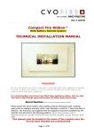
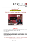
PIN NUMBER: 0558-CN1371 Rev 1 MADINI™ With Battery Remote System TECHNICAL INSTALLATION MANUAL IMPORTANT READ INSTRUCTIONS FULLY BEFORE STARTING TO INSTALL THIS APPLIANCE. INSTALLATION MUST BE COMPLETED BY A REGISTERED GAS SAFE ENGINEER. Serial Number ……………………………… Please quote this serial number when calling to discuss any aspect of this product including installation, ordering spare parts and making a warranty claim. Your Warranty is valid for 1 Year from date of delivery. The Warranty card supplied is to be filled in and sent to Spirit Fires Limited. 4 Beaumont Square, Aycliffe Industrial Park, Newton Aycliffe, County Durham, DL5 6XN Once the appliance is commissioned the Gas Safe Engineer must hand this manual to the owner of the property. Page 1 of 56 Contents Page 3 Page 3 Page 4 Page 6 Page 7 Page 8 Page 10 Page 10 Page 11 Page 13 Page 14 Page 19 Page 20 Page 21 Page 24 Page 25 Page 25 Page 26 Page 28 Page 28 Page 28 Page 29 Page 29 Page 30 Page 34 Page 35 Page 36 Page 36 Page 36 Page 38 Page 39 Page 41 Description Unpacking the Appliance Parts List and Assembly Technical Data Construction Dimensions Installation of Gas Fireplace Gas Burner Construction Remote Control System Building and Installation Work Preparing the Fireplace Opening Installing the Metal Enclosure/Gas Fire Commissioning the Appliance Check Sheet Commissioning the Appliance. Fitting the Pebble Set Fitting the Optional Fascia Trim Final Checklist Complete the Installation Appliance Start up/Shut down Instructions Shutdown if Handset is Faulty Oxygen Depletion Pilot System Flame Direction and Reversal Spark Ignition Failure Warning Fire Guards and Hearths Fault Diagnosis/Troubleshooting Battery Remote System - Alarm Sequence Remote Control Components Burner Removal Service and Aftercare Requirements Servicing Instructions and Procedure Replacement Spare Parts List Fitting Spare Parts Gas Fire User Instructions Page 2 of 56 Description The installation should only be carried out by a GAS SAFE registered engineer, and in accordance with national and local regulations for gas. The installation must also be in accordance with relevant parts of local and national building regulations. For the Republic of Ireland, reference should be made to IS813 and ICP3 and any guidance notes from Bord Gais. The MADINI is a “Hole in the Wall” style fireplace with a fire basket gas fire that has ceramic pebbles. The fire is available for Natural Gas Only. The fire is powered by a Battery [6 x AA] remote control system. The fire is operated by a handset and an infra red magic eye positioned at the front of the burner. To operate the handset must point directly at the magic eye. The fire requires a minimum flue area of 123cm2 x 2m length. If a flue liner is used the minimum is 125mm x 2m length. If the fire is being installed in an existing brick built chimney it is advised to purchase and fit the gather as it will reduce the possibility of debris falling into the enclosure. The fire does not require any additional room ventilation or wall vent to operate. • • Standard Fire: o MADINI Fire basket gas fire. o Enclosure. o Fitting Instructions. o Remote Handset. Optional Extras: o Gather Unit to fit 125mm Flue Liner. o Manual Wall Switch. o Upgrade to Mains operate Remote o 4pc Stone or 1pc Metal Wall Trim. o To order additional parts call Sales on 01325-301020 Unpacking the Appliance Refer to the Parts lists and drawings as shown on Page 4 & 5. Carefully examine the carton for damage before proceeding. If it is obviously damaged, please contact the manufacturer on 01325-32722. If happy with the overall condition of the packaging proceed to unpack all parts and examine their general condition. If satisfied by the condition, proceed with the installation. NOTE: No claims will be accepted for damaged, faulty or missing components once installation has begun. Page 3 of 56 Parts List – MADINI - Firebasket Assembly • Fire is supplied as a Kit: A – Grate Cover B – Burner Assembly C – Outerbox Assembly D – Battery Compartment containing: - Battery Housing and 6 Heat Pads. E – Ancillary Items Bagged or Boxed containing: - Pebble Set (5 Large, 12 Medium and 12 Small) - Remote Control Handset - Installation Manual Page 4 of 56 Parts List – MADINI - Enclosure and Gather Assembly F – Enclosure Assembly. G – Gather Assembly (optional if purchased). Please check your delivery note. Any missing parts must be notified within 48 hours of delivery. No claims can be accepted after this period. Page 5 of 56 Technical data Install Specification Pilot Assembly Marking SIT-NG-9103 Gas connection 8mm O.D. tube Minimum flue diameter 125mm Diameter Minimum flue area 125cm2 Area Minimum flue height* Appliance Mass 2.0 m 10kg * measured from the top of the gather spigot. Fire Technical Data Gas Type Nominal Heat Input kW, Gross Countries of Destination I2H - G20 at 20mbar 4.9 AT, BG, CH, CZ, DK, EE, ES, FI, GB, GR, HR, IE, IT, LT, LV, NO, PT, RO, SE, SI,SK, TR. I2E - G20 at 20mbar 4.9 DE, LU, PL,RO 4.9 / 4.5 BE, FR 4.5 NL Gas Category and Supply Pressure Injector (1 per) 280 NG I2E+ - G20'G25at20'25mbar I2L - G25at 25mbar FIRE IS AVAILABLE FOR NATURAL GAS ONLY Page 6 of 56 Construction Dimensions See below technical drawings for construction sizes. Fireplace opening Size is 840mm (wide) x 250mm (high), enclosure depth is 306mm. Page 7 of 56 INSTALLATION OF GAS FIREPLACE Introduction If you have any queries regarding these instructions or require additional technical support or advice on the installation of our products, please contact our technical support team on 01325 327 221 Every appliance has been designed, manufactured and tested to ensure that it conforms to the current national and European DFE (decorative fuel effect fire) legislation. All CVO fires are given a 100% full function test at the factory before being shipped to the customer. Over 40 different settings and readings are recorded and filed at the factory. If installed as instructed the fire will work perfectly. Every fire receives a gas soundness test (bubble tested) to 150mBar, flow rated and given a 100% function test. This ensures that all CVO fires work fully when leaving the factory. When installed inline with the instructions in this manual the owner will enjoy many years of operation. Please take the time to read the instructions fully. This fire is intended for decorative purposes. The installation must be in accordance with National Regulations and must be carried out by a qualified installer. Clearances between the fire and all combustible materials must conform to National Regulations. This fire must be installed and used in accordance with these instructions. Prior to installation, ensure that the local distribution conditions (identification of the type of gas and pressure and the adjustment of the appliance) are compatible. The builders opening or fireplace opening must be constructed of a non- combustible material. For some countries a non-combustible hearth must be fitted in front of the fire in accordance with National Regulations (e.g. United Kingdom). For some countries a purpose provided air supply must be fitted in accordance with National Regulations. Any flue damper plate or flue restrictor must be removed or fixed permanently in the fully open position, or shall only be fitted in accordance with National Regulations. The chimney must be swept before the appliance is installed. The unit must not be installed unless the chimney/flue length is at least the distance indicated on page 6 (minimum flue height). Before the fire is installed a flue test in accordance with National Regulations should be carried out. Page 8 of 56 The gas connections must be in accordance with National Regulations. An isolation valve, or valves, has to be fitted adjacent to the appliance which, when closed, allow(s) the complete burner and control assembly to be disconnected for maintenance or repair in accordance with National Regulations. The pilot light and flame sensing device fitted to this fire is also an atmosphere sensing device. If for any reason any part of the pilot assembly is to be replaced ALL the assembly including the pilot burner, thermocouple, electrode and injector must be exchanged complete for an original manufacturer’s pilot assembly only. This atmosphere sensing devise is not adjustable and must not be put out of action. The pilot light shuts off both the main burner and pilot if evacuation of the combustion products is interrupted. If the fire shuts itself off, do not use the fire, and have the flue and fire checked by a suitably qualified person. For some countries a purpose provided air supply must be fitted in accordance with National Regulations. It is recommended that a guard be used for the protection of young children, the elderly or infirm. This fire should be checked regularly to ensure that it is free from obstruction. A qualified person should service the fire regularly. After installation, the chimney should be inspected and swept regularly to keep the flue clear and free from debris and excessive build up of soot. The fire needs to be covered up when work is undertaken, to ensure the unit does not get damaged or gas outlets blocked. Do not throw rubbish on the unit, as this will block or hamper its efficiency. Due to the newness of the materials, the fire may give off a slight smell for a period of time after commissioning. This is quite normal and any odours should disperse within a few hours of operation. Page 9 of 56 Gas Burner Construction Take some time to review the burner construction taking note of the positions of the main components and the required connections. Before starting to install the appliance review the Data Plate fitted to the appliance for the gas type and pressure requirements of the appliance. Ensure these are correct for the property supply. This gas burner has a battery remote control system and requires only the connection of an 8mm gas supply. The remote is operated via a handset and infra red magic eye positioned on the appliance. The appliance is supplied with a fully tested and working gas burner. There is no need to dismantle or adjust the burner. Removal of any connections will result in the warranty being invalidated. Great care must be taken when handling the burner to avoid damaging the remote system. Remote Control System Take some time to learn about the remote system that is fitted to this fire. There is no need to remove any connections from the remote system during installation. Removal of any connections will result in the warranty being invalidated and no claims will be accepted for the unit not working. The gas burner is operated by an infra red remote control system that is powered by batteries. The fire is supplied with a hand set to switch the fire on/off and regulate the flame up/down. In order to operate the appliance the handset must be pointed directly at the magic eye (line of sight) on the fire. The hand set has a child safe feature to avoid accidental lighting. Please read “lighting the fire” section later in this handbook before operating the appliance. The remote is powered by 6 x ‘AA’ Batteries in the appliance and a 9V battery in the handset. A warning sound when the internal batteries become low will be heard however if the batteries are totally dead there will be no sound. If the appliance fails to operate on the hand set change the batteries in both the appliance and the hand set as this is the most common cause of failure. It is recommended that high quality “Lithium” batteries are used in the remote system to ensure that the fire operates the longest without replacement. Never fit “old” batteries as the black box has a sensor which will make a continuous alarm. Always fit new lithium batteries. If the fire shuts down it is set in “safe mode” to reactivate the fire press button #1 only on the handset. This will cause a beep. Now the fire can be lit again using the standard start-up sequence. The remote system has a fault diagnosis system built in. A fault is indicated by a series of “beeps”. Review the “fault diagnosis” section for the codes and descriptions. Page 10 of 56 Building and Installation Work All building and gas installation should be carried out by a qualified and competent person, and must adhere to national and local legislations and regulations. All gas work or work which involves installing the gas appliance in anyway must be done by a GAS SAFE engineer. Failure to observe this may make the appliance dangerous and will invalidate the warranty. Before Starting Building work should only commence after a thorough survey of the intended location of the impending installation has been completed and it has been established that the unit can be installed and operated without risk to the owner or tenants of the property or their neighbours. Enclosure: The enclosure has been designed to sit flush with the finished wall with a recess (top and bottom) to allow a suitable finishing material to be brought up to the fire opening. The enclosure and flue must be sealed inline with building regulations. Gather: This is supplied as an optional extra. The gather is used to join the enclosure to a 125mm class 2 flue liner with a minimum length of 2 metres. It is advised that a gather is always used as this will reduce debris entering the enclosure and will improve the efficiency and flame quality. This gather should be ordered with the appliance however if this has been missed this can be ordered from Customer Services on 01325-327221. Room Ventilation: The flue flow on this appliance has been tested and it does not require any additional room ventilation. Gas Supply & Pipe work: Before commencing to create the fireplace opening for the Madini enclosure note where the gas supply is. The gas supply pipe should run into the installed enclosure from either the rear, or right hand side. Consult the Data Plate within the appliance to ensure the correct gas type and pressure is available within the property. The gas burner has an 8mm inlet via an isolation valve. The fire also includes a pressure test point elbow to test inlet pressure. The gas pipe work should be routed into the enclosure via the available access holes. If the gas pipe work is over 1.5mtrs in length it is recommended that the pipe work is increased in diameter from this point to 15mm and possibly 22mm depending on the length to the meter. This will ensure a stable gas supply. To commission this appliance the gas pressure must be tested at the test point within the appliance and must be within 19mBar to 21mbar “with the fire operating on full”. If in doubt about the condition of any existing pipe work it is strongly advised to fit new pipes. All unused gas inlet points in the burner chassis must be sealed with metal tape. Failure to do this may result in flame reversal which will damage the remote system. Flame: If a flue system in excess of the specified length is used this may cause a very strong draw to occur which will result in the flame being effected. It is normal for the flame to be angled towards the back of the enclosure. Page 11 of 56 Ceramics: The pebble set supplied with the fire MUST be used. No other ceramics are to be placed on the gas burner. Flue System: A simple smoke test will reveal whether or not the chimney is working correctly. This fire is approved for use with a minimum flue area of 125cm2 and minimum length of 2 metres. This is equivalent to a 125mm flue liner with 2m length. If using in a larger or class 1 chimney it is advised to use the gather to reduce the draw and improve the efficiency and flame quality. Remote Heat Shields: The gas fire burner is fitted with heat shields to protect the components. If these are removed the fire will be damaged. No claims will be accepted for melted or damaged parts caused by using the appliance without the heat shields. Where existing chimney systems are to be used in conjunction with the Madini, they should have been swept and undergone thorough examination to ensure that they are in a sound and safe condition, as well as providing an adequate draw when the gas fire unit is in operation. Burner Ventilation: This is provided by the holes in the Grate cover. It is vital that the burner and grate cover are installed in the correct orientation and with none of the holes covered (except where directed during pebble set installation). Failure to ensure the correct flue and burner ventilation requirements are met as outlined in this manual will result in damage to the fire which is not covered by the warranty. Page 12 of 56 Preparing the Fireplace Opening Suggested Builders Opening: Height – 450mm, Width – 870mm, Depth – 320mm The height is to be reduced and sealed once the unit has been fitted. It is important that the gas supply is disconnected before any existing gas fire is removed. The MADINI enclosure should be located centrally to the existing chimney or flue at the desired height. If the fire is not placed central to the chimney, and the gather not used, the flame quality will be affected. The Madini does not have its own support lintel and a support lintel is not supplied with the unit. In some installations it may be necessary to install a lintel above the opening, if so an allowance must be made to accommodate the lintel. Measuring from the floor surface, the intended location of the base of the enclosure unit is marked onto the wall. Allowances must be made for the steel gather, if required. The area indicated on the wall must be removed to house the enclosure and burner unit. To create a seal around the appliance and allow correct operation of the chimney system, the original fire opening must be closed using bricks or blocks, infill the void around the enclosure using block work or rubble. The base should then be rendered to create a sealed base to support the enclosure. See following instructions and drawings. Page 13 of 56 Installing the Metal Enclosure/Gas Fire This fire is supplied with an enclosure and separate burner assembly. There are separate installation methods depending on if the gather is used or not. Refer to the notes below before starting to install the enclosure. It is best to dry fit the Enclosure unit first to ensure clarity this can ensure a clear route for the gas. Note: Position the Enclosure in the opening so that the front edge is aligned with the final face of the finished wall or slightly protruding (1mm) into the room. Please note that if a wall cover (Plasterboard) is to be added this must be taken into account. This appliance has been designed to draw combustion air through the holes in the grate cover, therefore any utility access points in the Enclosure assembly should be sealed with metal tape to ensure that the combustion air is only taken through the grate cover. TIP: Before fitting the enclosure it is advised to extend the gas pipe work out into the enclosure. The enclosure should be dry fit into the opening and the gas pipe work extended into the opening to allow for adjustments once the enclosure and burner are fitted. Page 14 of 56 Construction without the Gather If the standard gather is not used, the flue must be connected to the enclosure in accordance with GAS SAFE and local regulation. When installing the enclosure into an existing chimney or with a flue liner the enclosure & gather must be sealed to the existing chimney to ensure that air cannot flow behind the enclosure (flame reversal). Failure to do this will result in serious damage to the burner unit and enclosure. This damage is not covered by the warranty. See relevant sections below. Page 15 of 56 Enclosure with Optional Gather Unit The optional gather is available to join the enclosure to a 125mm flue liner. If installing the fire into an existing brick built chimney which complies to the requirements of the appliance it is strongly advised to still use the gather as it will improve flame quality, improve efficiency and stop debris entering the opening. Dry fit the gather to the enclosure taking note of where the gather and enclosure overlap. The builder will need to ensure adequate space above the enclosure is provided. The Gather will need to be positioned into the void above the enclosure before the enclosure is slid into the opening (unless the enclosure height is increased to allow the fire to be fitted with the gather as one unit). Once that the gather has been lined up with the enclosure it must be sealed using suitable high temperature silicone sealer or metal tape. Screw the gather to the enclosure using the 8 screws provided. Page 16 of 56 Fitting the Gas Burner. Once the Enclosure is fully sealed to the chimney the Madini Fire basket burner can be fitted. Before starting, look at the burner image below and the actual unit and take note of the magic eye, battery, isolation valve and pilot assembly as shown on the image below. The burner assembly must be positioned with the pilot at the back of the enclosure and the battery box and magic eye located to the front left as shown. Take care not to scratch the enclosure whilst lowering the burner. Use a piece of card to protect the paintwork at the back of the closure. The gas pipe should be fed into the chosen access hole and the burner unit placed into the enclosure slot and laid flat. If the burner is not flat remove the burner and correct any obstruction. See image below showing correct assembly of the burner. Page 17 of 56 Gas and Battery Connection. Image showing Pressure Test Point and Isolation Valve. Taking care not to damage the burner assembly or remote wiring connect the prepared 8mm inlet gas pipe to the isolation valve which is fitted in the right hand side of the burner. The gas pipe should be fed into the chosen access hole and the burner unit placed into the enclosure slot and laid flat. If the burner is not flat remove the burner and correct any obstruction. Any unused gas access points should be sealed with metal tape. Image showing Pressure Battery Pack and Insulation Pads. The battery pack should now be connected to the power lead and the pack fitted into the battery holder, ensure all 6 heat pads are in place and the battery wire is inserted into slot away from burner. WARNING: Never use the appliance without the top battery cover in place. With the isolation valve in the OFF position the gas line should be tested for leaks. Take some time to read the section on “lighting the fire” and then open the gas isolation valve ready for lighting and commissioning the appliance. Page 18 of 56 CVO Commissioning Checklist Important Notice Explain the operation of the appliance to the end user, hand the completed instructions to them for safe keeping, as the information will be required when making any guaranteed claims. Pass Flue Check Fail 1. Flue is correct for appliance 2. Flue Flow test 3. Spillage test Gas Check 1. Gas soundness & let by test 2. Standing pressure test 3. Appliance working pressure (on High Setting) NB All other gas appliances must be operating on full 4. Gas rate 5. Does ventilation meet appliance requirements Dealer and Installer Information Installation Company……………………………………………..………………… Address …………………………………………… ………………………………… ………………………………………………………… Engineer………………………………………… Contact No……………………………………… Gas Safe No…………………………………… Date of Installation………………………… Date of Purchase…………………………… Model No………………………………………… Gas Type ………………………………………… This product is guaranteed for 1 year from the date of installation, as set out in the terms and conditions of sale between CVO and your local CVO dealer. This guarantee will be invalid, to the extent permitted by law, if the above Commissioning Checklist is not fully completed by the installer. Page 19 of 56 Commissioning the Appliance All of the results that are measured while testing the fireplace are to be entered into the “Commissioning Check sheet” on the back page. This is to allow for a record to be kept should there be any issues in the future. COM#1 - TEST THE GAS PRESSURE: To gain access to the pressure test point, this will need to be done with the inner burner chamber in place and without the pebbles and grate cover on. 1. Attach a calibrated manometer to the inlet test point. This is the only point at which the gas pressure should be measured. Failure to take readings here may render the appliance dangerous. 2. With other gas appliances in the house switched off light the fire and set the burner on full. It may take lots of attempts to light the fire the first time if the gas line has not been purged of air this will take a long time as the pilot hole is very small. 3. Allow the fire to run for approx 5 minutes. 4. Check the gas inlet pressure reading on the manometer. The pressure must read between 19mBar - 21mBar. If the reading is outside of these readings read the section “failure” below. If passed continue with the next test. 5. Now turn on the other gas appliances in the house and take the pressure reading again. The pressure must read between 19mBar - 21mBar. If the reading is outside of these readings read the section “failure” below. If PASSED all of the above tests then switch off the fire and remove the manometer. Refit the test point screw and ensure it is sealed. Now move to the section “fitting the pebbles” If FAILED any of the tests above: 6. The fire is not safe to use. The gas pressure problem must be investigated and corrected. This may require upgrading the pipework and removing any blockages. If the pipe work is not to blame the problem may be with the meter. Please contact your utility supplier to adjust the governor to the house before the fire can be commissioned further. Do not leave the fire operational with incorrect gas pressure. Page 20 of 56 Fitting the Pebble Set Ensure that the pressure test point has been resealed then carefully place the grate cover over the burner ensuring the holes line up. Check the magic eye position has not been disturbed during installation and that it is the correct way round (as shown) to ensure “line of sight” and correct operation. Once tested the Grate cover should be fitted taking care not to scratch the enclosure or the cover. Shown Above: magic eye and emergency cut off switch with Grate cover on. • The pebbles must be set out as below. No other Ceramics are to be fitted to this appliance. #1 Ensure slotted burner tray is in place. This has a symmetrical pattern to ensure it cannot be placed incorrectly. #2 Ensure grate is correctly placed over burner as shown. The grate will sit flat with the burner sitting inside the centre hole and the pilot / IR sensor within their cut-outs. Page 21 of 56 #3 Add 6 medium pebbles marked MV and 2 small pebbles marked SV in the configuration shown ensuring the pilot is left clear and not obstructed. #4 Find the pebble marked LV with the cut out as shown above. #5 Place this pebble (#4) in the centre with the cut-out pointing down and towards the pilot as shown. Ensure that the pilot and closest hole on the burner tray are not obstructed. Page 22 of 56 #6 Add 5 large pebbles marked LV and 5 small pebbles marked SV as shown. #7 Finally add the remaining 6 medium pebbles marked MV and 5 small pebbles marked SV as shown. WARNING: Check that the pilot, pilot hole and hole on burner tray closest to pilot are still unobstructed as this is critical to ensure the fire and pilot operates safely. Page 23 of 56 COM#2 -TEST THE FLUE: The installer must check that all of the combustion products are entering the flue after 10 minutes by traversing the perimeter of the fireplace opening using a smoke “match”. Ensure the flue and enclosures are sealed. Fitting the Optional Fascia Trim This appliance has been designed so that the combustion air required is drawn through the opening and into the grate cover holes. This has an added advantage of allowing a custom built fascia or surround to be fitted by a builder (which must meet any relevant regulations and be of an appropriate material) to the wall around the fire so long as the opening size remains unchanged. Please contact our sales department for details of optional fascias. Page 24 of 56 Final Check List • • • • Are the Flue & Enclosure sealed to ensure no air can travel around the sides or back of the enclosure into the burner cavity? Are all other access holes in the burner tray sealed with metal tape? Are heat shields fitted above the control box and around the batteries? If you have any questions, or the fire is not operating correctly, read the manual again and refer to the troubleshooting section. If additional technical help is required please call 01325-327221 before you leave the installation. Complete the Installation BRIEF THE CUSTOMER: • How to light and shut down the appliance. • How to change the hand set batteries. • How to change the main appliance batteries ensuring the heat pads, the grate cover and pebbles are replaced in the correct location. Noting that the pilot must be kept clear of pebbles. • The customer must be told not to change the pebble arrangement from that shown. • The customer must be told of the need for regular servicing of the appliance, at least once a year. • The customer must be made aware that no rubbish is to be thrown onto the fire bed. • The customer must also be aware that purpose provided ventilation should be checked regularly. • Complete the commissioning check sheet on the back page. • Complete the warranty card and give this to the customer. • Give the customer the instruction booklet. Page 25 of 56 IMPORTANT TECHNICAL INFORMATION Appliance Start Up / Shut Down Instructions The appliance is supplied with an internal battery power supply and is operated via handset. There are 6 x ‘AA’ batteries inside the appliance and 1 x 9V battery in the handset. Only use good quality batteries to ensure a long life. If the main burner or pilot light is extinguished during lighting, do not attempt to re-light the pilot within three minutes. To Reset the Appliance: If the appliance is shut down unexpectedly the valve must be reset first before the fire can be re-lit. This can be done by pressing the “OFF” (button #1) until a beep is heard. Wait a few seconds then commence the starting sequence as detailed below by pressing both left hand buttons at the same time. Using the Handset (see image). Each time a button is pressed a “beep” will be heard. • • • To Light the Fire – As a “child proof” system both buttons #1 & #2 must be pressed at the same time for a number of seconds until the ignition (spark) sequence starts. To operate correctly the handset must be pointed directly at the magic eye on the appliance. When the pilot flame presence is detected (ionization flame control) the system holds for 10 seconds to warm the thermocouple. Once the thermocouple is warm enough to hold the magnet unit the valve will allow gas to the burner at the maximum setting. In case of failure during pilot ignition sequence, the EDB puts the system in safe mode. To restart the ignition sequence press Button #1 again. Standby Mode - It is possible once the fire is lit to operate in standby mode with pilot only lit. To do this press button #2. • High Setting - By pressing Button #3 the burner flame is increased to the maximum rate. • Low Setting - By pressing Button #4 the burner flame can be reduced to the minimum rate. • Turn Off - To turn the appliance OFF Button #1 is pressed. Page 26 of 56 To Summarise: o Button #1 & #2 together – This switches the appliance ON. o Button #1 – This switches the appliance OFF and Resets the Appliance. o Button #2 – This sets the unit into standby mode (pilot only) o Button #3 – This sets the flame at maximum rate. o Button #4 – This sets the flame at minimum rate. Each time a button is pressed a “beep” will be heard. Page 27 of 56 How to Shutdown if the Handset is Faulty The appliance has a safety shut down switch which is built into the remote system. This is in the form of a button fitted on the appliance, next to the magic eye (see photo below). In the unlikely event that the handset is lost, damaged or broken while the fire is lit the fire can be shutdown by pressing this button. Safety Shutdown Procedure • Taking great care as the appliance will be hot, use the stubby end of a pen, or similar, to press and hold the button for up to 60 seconds. • The appliance will shut down. • Do not use the appliance until the handset has been repaired or replaced. • To purchase a new handset call 01325-327221. Oxygen Depletion Pilot System There is a highly sensitive oxygen depletion sensor designed into the pilot light. If any part is damaged the entire unit must be replaced. Do not attempt to bend or alter the flame head, thermocouple or aeration hole. Use only genuine spare parts as similar looking parts from other appliances may well give different or inferior performance and could lead to a hazard. Flame Direction and Reversal The flame on this type of appliance is normally directed towards the rear of the enclosure. This is normal due to the opening size and flue system. The flame will never stand “upright”. It is to be expected that over time the surface on the rear of the enclosure will tarnish. This is typical “wear and tear” for a gas fire. If the flame is drawn under the shelf this highlights a serious installation fault and the appliance must not be operated until the cause is found. A typical cause would be unsealed burner holes or failure to seal the enclosure and flue (flame reversal). Page 28 of 56 Spark / Ignition Failure The gap between the pilot electrode and the pilot should be 3.5 – 4.5mm and normally adjustment is not necessary (the electrode is very brittle). The spark should jump across the gap between the electrode and the gas outlet on the pilot head. The If the ignitor fails, a lighted taper can be inserted into the pilot area to check that gas is reaching the pilot. Warning: Fire Guards & Hearths This appliance is not fitted with an integral guard. In normal use consideration may be given to the use of a fireguard conforming to BS6539 or BS6778, so that the approach to the appliance is limited such that access to the flame is minimised It is recommended that a fireguard conforming to BS6539 or BS6778 is used for the protection of young children, the elderly and infirm. The installer is to advise the user not to stand too close to the appliance for prolonged periods of time and warn that loose clothing is particularly at risk of burning due to the presence of an unguarded flame. In addition, the installer is to advise the user against placing combustible material directly in front of the appliance. Floor coverings, such as carpets, are considered to be acceptable. For some countries a non-combustible hearth must be fitted in front of the fire in accordance with National Regulations (e.g. United Kingdom). Page 29 of 56 Fault Diagnosis/Troubleshooting • • • • • • The system “beeps” all the time: Count the sequence of beeps and check the fault diagnosis system codes as shown on page 30. The fire “clicks” but does not light. o Check that there is a spark at the pilot. If not it indicates the ignitor lead has become detached. If yes air must be in the gas line – wait for it to purge. The pilot “lights” but the main burner will not start – this may be: o Low gas pressure – see commissioning. o a fault on the thermocouple lead into the valve – check it’s not loose. o This indicates a damaged thermocouple – fit a new pilot assembly. o This indicates that the valve may be faulty [is the remote beeping?] The Burner lights but turns off the appliance after a few minutes. o This is normally caused by gas pressure. The pressure is not enough to make a good pilot flame which causes the thermocouple to cool and shut down the fire. See commissioning. o This may also be a faulty pilot assembly – replace the pilot. The Burner lights but turns off the appliance after a long time. o This may also be gas pressure, the pressure is not enough to make a good pilot flame which causes the thermocouple to cool and shut down the fire. See commissioning. o This may also be caused by a faulty chimney where there is spillage or downdrafts causing the safety device to shutdown the appliance. o Do not use the fire until a gas safe engineer has inspected the chimney. For additional help see the diagnosis flow charts in the following pages. Page 30 of 56 Ignition Functional Check 1 – Remote Fires PILOT WILL NOT LIGHT Ensure there is no debris around the pilot assembly, (e.g. soot, etc.) which could short the spark, clean the area. Clean the Electrode with a fine sand paper to ensure a good spark is created. Ensure the Electrode gap is 4mm. No Yes Operate the valve. Is there a spark? Does the Pilot light? Yes No Consult User Instructions (see lighting section) and retry. No Is the control being operated correctly? Yes Check alignment of pilot burner head. Check the Electrode Gap is 4mm. Change the ignition lead. Yes Will the pilot light with a match? No No Check isolation tap and gas meter, retry. Is the gas turned on to the appliance? Yes Correct pipe work to the appliance to ensure it complies with the Kw rating of the appliance, Check for leaks and Retry. No Is the gas pressure correct? Using a Manometer on the test point within the appliance check the inlet pressure is within +/-1mBar of the level on appliance data plate. Any lower than this and the appliance will not light. Yes Purge the gas pipes and retry. Check for gas leaks. Check Pressure again. Yes Has the system got any air in it? No There is a blockage in the system, check the inlet test point, the mag seating and valve. Check thermocouple leads for correct orientation, condition and connection. Go to the next chart ignition functional check 2 System Ok Page 31 of 56 Ignition Functional Check 2 [Remote Fires] NO SPARK Ensure there is no debris around the pilot assembly, (e.g. soot, etc.) which could short the spark, clean the area around the pilot. Clean the Electrode with a very fine sand paper to ensure there is a strong spark created. Ensure Electrode Gap is 4mm. Consult the users instructions, retry. No From Ignition fault finding Chart 1 No Is the valve being operated correctly? Yes Correct and retry. Yes Is the gap between electrode and thermocouple 4.0mm? Yes Has ignition lead become detached or is connection poor? No Yes Check handset batteries are OK. Replace if required. Check handset is not damaged [been dropped?] Check the batteries or mains [240v] supply to the control unit [black box]. Replace batteries or electrical fuse if required. Retry again with handset and manual switch. Remove the ignition lead from electrode. With insulated pliers. Hold the tip 4.0mm from the pilot pipe work, is there a spark when the system is operated? No Has the ignition lead become detached from the control box? Yes No Replace the lead, retry. Replace the electrode. Replace the ignition lead and retry. Page 32 of 56 Yes Flame Failure Functional Check 3 [Remote Fires] PILOT WILL NOT STAY LIT OR FIRE GOES OUT IN USE Ensure there is no debris around the pilot assembly, (e.g. soot, etc.) Check for fluff in the pilot aeration hole. Check the Thermocouple nut into the valve is tight. Light the pilot using either the handset or the manual wall switch. With the pilot running is the gas pressure at the test point in the appliance as stated on the data badge? No No Will pilot stay alight? Yes Problem is with the pipe work or fittings which lead to the fire. Correct and retry. With the fire running on FULL is the gas pressure at the test point in the appliance as stated on the data badge? [see note No below] Yes Yes No Is the pilot flame of the correct length? Are the No thermocouple leads damaged or loose in the interrupter block? Is the on/off switch in the ON position. See diagram? Is the thermocouple connection good in back of valve? No Yes Yes Is the flue working? Check for Spillage. Is there Room No Tighten the connection and retry. Replace pilot unit. Yes Rectify This. No Will pilot stay alight? Change the pilot unit or damaged thermocouple leads Run for 3 minutes; Turn off, time interval until mag unit shuts with a click. Is this greater than 7 seconds? Change mag unit. System Ok Page 33 of 56 Yes Run for 3 mins, turn off, time interval until mag unit shuts with a click. Is this greater than 7 seconds? Battery Remote System – Alarm Sequence This fire is operated via a battery remote system with AA batteries. The remote system has a built in alarm system which indicates and faults which may arise. This is shown by a sequence of a pre-defined number of “beeps” corresponds to a certain failure. BLACK BOX – ACS2 IR Alarm sound description 2 x Beeps = Low battery alarm. In case of low battery voltage (supply voltage below 6V) the buzzer produces a sequence of 2 beeps with a repetition rate of 1s. To resume the normal operation it’s necessary to recharge or substitute the battery with a new one and to verify the alarm sound is no more present. 3 x Beeps = Manual Wall Keyboard failure sound. In case of keyboard failure (i.e. cable opens or pushbutton stuck closed) the buzzer produces a sequence of 3 beeps with a repetition rate of 1s. To resume the normal operations it’s necessary to substitute the keyboard with a working one and to verify the alarm sound is no more present. 4 x Beeps = Motor Failure sound. In case of motor failure, the buzzer produces a sequence of 4 beeps with a repetition rate of 1s. To resume the normal operations it’s necessary to substitute the valve with a working one, to repeat the ignition sequence and to verify the alarm sound is no more present. 5 x Beeps = Driver leakage sound. In case of on board motor driver current leakage failure the buzzer produces a sequence of 5 beeps with a repetition rate of 1s. To resume the normal operation it’s necessary to substitute the board with a working one, to repeat the ignition sequence and to verify the alarm sound is no more present. 6 x Beeps = Under voltage low battery. In case on under voltage low battery (supply voltage less than ADC circuit reference power supply); the buzzer produces a sequence of 6 beeps with a repetition rate of 1s. To resume the normal operations it’s necessary to substitute the battery with a new one and to verify the alarm sound is no more present. Only use high quality Alkaline or Lithium batteries in the appliance and hand set to ensure a long and reliable life. NEVER USE old batteries, the set must be replaced as a complete set of new batteries. Page 34 of 56 Remote Control Components Page 35 of 56 Burner Removal If the burner needs to be removed for repair see section on servicing for instructions on how to remove the burner. Service and Aftercare Requirements When completing the annual service of the unit, refer to the enclosed technical installation and operational manual & the remote control instruction document. The gas unit should be installed to the manufacturer’s instructions by a Gas Safe registered gas installer, every 12 months the gas fire unit should undergo a regular service, this work should be carried out by a competent person who is Gas Safe registered, familiar with the CVO Fire range of goods. When carrying out the annual service, the competent person should examine and verify the following; • • • • • • The correct safe operation of the ODS (oxygen depletion system) That the fire unit correctly cross-lights A pressure drop test to verify that there are no gas leaks That the electronic ignition system operates correctly That the burner surface is free from damage and debris That the owner has a copy of the installation and operation manual Servicing Instructions and Procedure General CVO Recommend that this appliance is serviced every 12 months by a GAS SAFE Engineer. The following servicing procedure should be carried out regularly and only by a qualified person. Note: foreign bodies, which can gather on the surface of the burner unit, it is inevitable that servicing can be a dusty operation. Suitable precautions should be taken. Important: The pilot and flame sensing device fitted to this fire is also an atmosphere sensing device. If for any reason any part of the pilot assembly is to be replaced, the entire assembly including the pilot burner, thermocouple electrode and injector must also be exchanged. This atmosphere sensing device is not adjustable and must not be disabled. Page 36 of 56 Servicing Procedure • • • • Turn off the fire and allow cooling time. Turn off the gas supply at the isolation tap. Remove the pebble set and the grate cover. Using a 7mm spanner loosen (but do not remove) the 4 nuts on the legs of the burner. The burner will lift then slide out as shown. • Using a 15mm Spanner carefully remove the injector. • Clean the injector and remove blockages. Do not use a needle or wire, as this may widen the journals, which are set to the C V O test standards. Using a soft brush or vacuum cleaner, carefully remove any debris from the burner unit. Make sure the pilot journals are clear and free from dirt. Re-assemble the fire in the reverse order, and re-connect the gas supply then check for soundness. Check the pilot for a good flame. Re-commission the fire (Page 19). • • • • • Page 37 of 56 EXCHANGEABLE PARTS Shown below is a list of exchangeable parts, these are separated into categories, “User” and “Engineer”. The parts listed under engineer must be changed by a registered GAS SAFE engineer only. Spare parts are not returnable. CVO fire cannot accept responsibility for incorrect parts being ordered. When ordering replacement components or requesting technical assistance, you should at all times quote the following information: Type of fire & serial number as shown on Data Plate, the component part number and description of fault. For spare parts please call 01325 – 327221 and ask for customer service. ENGINEER REPLACEMENT PARTS Item description 8mm Isolation Tap 8mm Pressure Test point Pilot Asst – SIT-9103 NG Injector – 280 Black Box – 30106850000 Remote Valve – 81104711000 Remote Link Battery Cable Magic Eye (IR Receiver) HT Lead - 30106600401 Code AC026 AC082 AC001 AC072 GC049 GC050 GC053 GC060 GC012 GC032 Replacement Method See Page 39 See Page 39 See Page 39 See Page 39 See Page 39 See Page 39 See Page 39 See Page 39 See Page 39 See Page 39 USER REPLACEMENT PARTS Item description Battery Holder Remote Handset – 30106800101 Pebble Set (5L/12M/12S) Code KC098 GC052 KC031 Page 38 of 56 Replacement Method See Page 48 See Page 46 See Page 48 Fitting Spare Parts The fitting of replacement parts must be carried out by a qualified GAS SAFE Engineer inline with current regulations. When removing any serviceable parts great care should be taken to assemble the parts in the correct manner to ensure the fire functions as designed. Follow the procedure for Burner removal see servicing section page 36. Remove the heat shield from the 2 studs to reveal the components below. Keep the nuts and spacers for refitting later. Special Notes in relation to component replacement: Wires and leads into Black Box: Refer to wiring diagram on page 35 for replacement of leads. Take care to ensure after replacement no leads come into contact with the burner unit or become damaged. Pilot unit: Remove the two nuts holding the pilot bracket in place (keep any spacers for refitting later). The pilot and bracket can be lifted out in one piece. Remove the 2 screws holding the pilot to the bracket and replace the pilot. Refit the bracket and ensure the pilot is in the correct position. Page 39 of 56 Page 40 of 56 MADINI™ With Battery Remote System USER HANDBOOK PIN NUMBER: 0558-CN1371 This manual must be handed to the owner of the property once commissioned Page 41 of 56 Contents Page 43 Page 44 Page 45 Page 47 Page 48 Page 52 Page 53 Page 54 Page 54 Page 55 Page 56 General Information Lighting the Fire Appliance Start Up / Shut Down Instructions Shutdown if the Handset is Faulty Replacing the Batteries Cleaning Instructions Service and Aftercare Requirements Warranty Information Warranty : Bespoke Fireplaces Warranty : Heat Damage Contact Details Page 42 of 56 General Information A qualified GAS SAFE registered installer is required to fully install the appliance, failure to do this may render the appliance dangerous and will invalidate the warranty. This fire is intended for decorative purposes. Any purpose-provided ventilation should be checked regularly to ensure that it is free from obstruction. The fire should be serviced regularly by a qualified person. The chimney should be swept before the appliance is installed, and should be swept and inspected regularly to ensure that all of the products of combustion are entering the flue and there is no excessive build up of soot. Do not throw rubbish etc on the burner surface area or otherwise disturb the fuel bed. Debris from any source, or soot formed, should be removed from time to time, see ‘Cleaning instructions’. Do not alter the pebble arrangement from that shown or interfere with the burner unit as doing so maybe dangerous and will invalidate the warranty. The pilots ODS (Oxygen depletion sensor) must not be put out of operation. The user must not adjust the pilot. If any of its parts are damaged and need to be exchanged the original manufacturers parts must be used. Once the flue and fire units have been checked and remedial action taken, the fire is ignited in the manner depicted in section ‘Lighting the fire’. Due to the newness of materials, the fire may give off a slight smell for a period of time after commissioning. This is quite normal and any odours should disperse within a few hours of operation. For some countries a purpose provided air supply must be fitted in accordance with National Regulations. This fire should be checked regularly to ensure that it is free from obstruction. A qualified person should service the fire regularly. Fire Guards: It is recommended that a fireguard conforming to BS6539 or BS6778 is used for the protection of young children, the elderly and infirm. Pilot Assembly: The pilot light and flame sensing device fitted to this fire is also an atmosphere sensing device, which shuts off both the main burner and pilot if evacuation of the combustion products is interrupted. If the fire shuts itself off, restart the fire following the procedure in section ‘Lighting the fire’. If the fire continues to shut itself off do not use the fire, and have the flue and fire checked by a suitably qualified person. Page 43 of 56 Lighting the Fire Infra-Red Remote Operation Infrared systems require “Line of sight” between the handset and the sensor at the appliance, it is a standard safety feature to ensure that the appliance cannot be remotely lit from another room. Page 44 of 56 Appliance Start Up / Shut Down Instructions The appliance is supplied with an internal battery power supply and is operated via handset. There are 6 x ‘AA’ batteries inside the appliance and 1 x 9V battery in the handset. Only use good quality batteries to ensure a long life. If the main burner or pilot light is extinguished during lighting, do not attempt to re-light the pilot within three minutes. To Reset the Appliance: If the appliance is shut down unexpectedly the valve must be reset first before the fire can be re-lit. This can be done by pressing the “OFF” (button #1) until a beep is heard. Wait a few seconds then commence the starting sequence as detailed below by pressing both left had buttons at the same time. Using the Handset (see image). Each time a button is pressed a “beep” will be heard. • • • To Light the Fire – As a “child proof” system both buttons #1 & #2 must be pressed at the same time for a number of seconds until the ignition (spark) sequence starts. To operate correctly the handset must be pointed directly at the magic eye on the appliance. When the pilot flame presence is detected (ionization flame control) the system holds for 10 seconds to warm the thermocouple. Once the thermocouple is warm enough to hold the magnet unit the valve will allow gas to the burner at the maximum setting. In case of failure during pilot ignition sequence, the EDB puts the system in safe mode. To restart the ignition sequence press Button #1 again. Standby Mode - It is possible once the fire is lit to operate in standby mode with pilot only lit. To do this press button #2. • High Setting - By pressing Button #3 the burner flame is increased to the maximum rate. • Low Setting - By pressing Button #4 the burner flame can be reduced to the minimum rate. • Turn Off - To turn the appliance OFF Button #1 is pressed. Page 45 of 56 • To Summarise: o Button #1 & #2 together – This switches the appliance ON. o Button #1 – This switches the appliance OFF and Resets the Appliance. o Button #2 – This sets the unit into standby mode (pilot only) o Button #3 – This sets the flame at maximum rate. o Button #4 – This sets the flame at minimum rate. Each time a button is pressed a “beep” will be heard. Page 46 of 56 Shutdown if the Handset is Faulty The appliance has a safety shut down switch which is built into the remote system. This is in the form of a button fitted on the appliance, next to the magic eye (see photo below). In the unlikely event that the handset is lost, damaged or broken while the fire is lit the fire can be shutdown by pressing this button. Safety Shutdown Procedure • Taking great care as the appliance will be hot, use the stubby end of a pen or similar to press and hold the button for up to 60 seconds. • The appliance will shut down. • Do not use the appliance until the handset has been repaired or replaced. • To purchase a new handset call 01325-327221. Page 47 of 56 Replacing the Batteries Main Appliance Batteries WARNING: Do not remove the Pebbles until the appliance has cooled down for at least 4 hours as they will be extremely hot. If the remote alarm indicates that the batteries are “flat” do not use the appliance. Ensure the appliance is switched off and has had time to “cool down”. Before starting to do this work we recommend that rubber gloves are worn whilst handling the heat pads and the ceramic pebbles as the ceramic fibres can cause irritation to the skin. Once the appliance is cooled, carefully remove the pebbles and lift the grate cover off the appliance. Take care not to knock or damage the pilot and or scratch the enclosure. (Do not touch, disturb or remove any other items than instructed). The battery box will be visible (See photos). Carefully lift the battery pack from its holder remove the flat batteries. Page 48 of 56 USE NEW “LITHIUM” BATTERIES - It is recommended that high quality “Lithium” batteries are used in the remote system to ensure that the fire operates the longest without replacement. NEVER USE “OLD” BATTERIES - The remote system has a sensor which monitors the battery age/quality. If a set is added which includes old or used batteries the alarm will continue to sound until a full new set are added. Insert 6 x AA batteries in the correct order and replace the battery pack in the holder. Ensuring no wires are disconnected tuck the wire carefully back into the slot in the metal holder and replace the heat pad as shown. Carefully refit the grate cover and arrange the pebbles as shown below. The burner unit should not be touched during battery changing. Hand Set Batteries Turn over the hand set and unclip the battery cover. Fit a new 9V battery and refit the battery cover. The appliance should now operate normally. NOTE: CVO Fire recommends that only high quality batteries are used in this appliance. Lithium batteries provide the longest life. Fitting The Ceramic Pebbles WARNING: • The fuel bed supplied with the fire must be used. • No other type of ceramics must be used with this fire. • The full set of pebbles must be fitted to the fire • The pebbles must be positioned on the burner as shown on Pages 51 & 52. Page 49 of 56 The pebbles must be set out as below. #1 Ensure grate is correctly placed over burner as shown. The grate will sit flat with the burner sitting inside the centre hole and the pilot / IR sensor within their cut-outs. #2 Add 6 medium pebbles marked MV and 2 small pebbles marked SV in the configuration shown ensuring the pilot is left clear and not obstructed. #3 Find the pebble marked LV with the cut out as shown above. Page 50 of 56 #4 Place this pebble (#4) in the centre with the cut-out pointing down and towards the pilot as shown. Ensure that the pilot and closest hole on the burner tray are not obstructed. #5 Add 5 large pebbles marked LV and 5 small pebbles marked SV as shown. #6 Finally add the remaining 6 medium pebbles marked MV and 5 small pebbles marked SV as shown. Check that the pilot, pilot hole and hole on burner tray closest to pilot are still unobstructed as this is critical to ensure the fire and pilot operate safely. Page 51 of 56 Cleaning Instructions Before cleaning the appliance turn off the Fire and allow it to cool for a number of hours. Before using any cleaning materials test a small area first to ensure compatibility with the appliance finish. CVO Fire cannot be held responsible for damage caused by cleaning the appliance. Burner Deposits It is normal for the burner to show a reddish or white deposit. This is caused by biproducts of the gas being burnt and is unavoidable. This can be remedied by using a stove paint like Hotspot High Temperature Stove Paint which is sold in 100ml cans online for approx £7. Similar products may also be available from major DIY stores or fireplace retailers. When painting the burner ensure the pilot assembly is not touched. Cleaning the Gas Fire Burner and Enclosure The most effective method of dust/debris removal is achieved with the aid of a vacuum cleaner however; great care must be taken to ensure that the pilot assembly is not touched. Using a vacuum cleaner with a soft brush head gently remove any debris/dust from inside the enclosure and around the burner unit. To avoid any pebbles being lost in the vacuum cleaner you may if required carefully remove the pebbles. Once all of the dust and debris has been removed the surfaces can be cleaned with the use of a soft cloth. Ensure that no liquid or debris falls into the burner or the appliance through any of the slots. If unsure then you must not use the appliance until a qualified Gas Safe Engineer has been able to inspect it. If the pebbles have been removed or become disturbed then refer to the section on changing the Main Appliance Batteries for the correct sequence and positioning of the pebble set. It is very important that the pebble arrangement shown is adopted as any other arrangement will invalidate the warranty. Removing spillages This appliance has an electronic remote system. Where a liquid has been spilled onto the surface of the fire or enclosure DO NOT USE THE APPLIANCE – contact your installer to ensure the remote system functions correctly. Wax Never place candles on the burner shelves. If molten wax enters the burner unit – DO NOT USE THE APPLIANCE - contact your installer to remove the spillage and ensure the remote system functions correctly. Page 52 of 56 Service and Aftercare Requirements When completing the annual service of the unit, refer to the enclosed technical installation manual and User manual. The gas unit should be installed to the manufacturer’s instructions by a Gas Safe registered gas installer. Every 12 months the gas fire unit should undergo a regular service; this work should be carried out by a competent person, who is Gas Safe registered, familiar with the CVO Fire range of goods. It is recommended also, that there should be a periodic inspection of the flue and fireplace opening. When carrying out the annual service, the engineer should examine the following: • The correct safe operation of the ODS (oxygen depletion system) • That the fire unit correctly cross-lights • A pressure drop test to verify that there are no gas leaks • That the electronic ignition system operates correctly • That the burner surface is free from damage and debris • That the owner has a copy of the installation and operation manual It is advised to buy a new pilot assembly before starting to service the fire. This will ensure the fire has a long life and is reliable. User Exchangeable Parts The only user exchangeable parts on this fire are shown below. All other parts must be fitted by a registered gas engineer. If the fire develops a fault, switch it off and consult an engineer – do not dismantle the fire. Item description Battery Holder Remote Handset – 30106800101 Pebble Set (5L/12M/12S) Code KC098 GC052 KC031 Page 53 of 56 Replacement Method Page 48 Page 46 Page 48 WARRANTY INFORMATION This appliance carries full CE approval and has a long and reliable history. The CE approval ensures that, if installed correctly, the appliance will function as designed. If the appliance develops a fault please refer to the fault diagnosis section earlier in this booklet for possible causes. To register your appliance please complete and return the warranty card supplied with the fire. This appliance is supplied with a 12 month warranty from the date of delivery. The Warranty covers defective parts only and does not cover typical wear and tear that occurs with a gas fire appliance. In order to make a warranty claim you will be required to supply the serial number of the appliance [as shown on the front of this book] and full details of the GAS SAFE engineer who installed the appliance - we may request a copy of the installation receipt. Failure to supply details of the Registered Engineer who installed the appliance will invalidate the warranty. If the unit develops a fault during the warranty period the burner unit must be removed and returned to the factory for repair. The returned unit will be retested and any fault confirmed. If the fault is due to the components failing Spirit Fires will cover the cost of burner removal and refitting. If the returned unit is found to not be faulty or the fault has been caused by incorrect usage the costs of checking and return will be chargeable to the customer. To raise a warranty claim call Customer Service on 01325-327221. Use Within Bespoke Fireplaces Where the Madini only burner has been purchased in must be installed inline with the guidance set out in this booklet. Failure to follow the instructions may render the appliance dangerous. Where the Madini burner only is supplied to be installed in a fireplace designed by others the warranty covers the burner unit only and Spirit Fires Limited will not accept any responsibility for any other damage or costs incurred by using the burner in this way. The warranty is limited to the return of the burner back to the factory for checking and possible repair. Spirit Fires Limited will not cover any costs of removal or refit of the burner. If the fault has been caused by incorrect usage or unsuitable fireplace design the costs of checking and repair will be chargeable to the customer. By purchasing the Madini burner for use in a custom designed fireplace outside the control of Spirit Fires Limited you accept this limited warranty as stated above. Page 54 of 56 IMPORTANT NOTE - “Heat Damage” This fire must never be operated without the heat shield in place over the Black Box and the 6 heat pads around the batteries. Failure to do this will result in serious damage to the remote system. The pad must be over the batteries as shown above. We will not accept any claims for “melted remote system”. In this instance in highlights a very serious issue over the installation of the appliance. The appliance has been tested to CE standards to ensure, when installed correctly, that all of the components operate within the designed temperatures. In the instance of the remote system becoming hot enough to melt it highlights an install fault not a component failure. Typical causes are – using the fire without the heat shield, incorrect burner ventilation, unsealed enclosure, an unsealed flue system or flame reversal. Before purchasing new parts to repair the fire the cause of the melting must be rectified. We will not accept any claims where the burner wiring or connections have been tampered with. Page 55 of 56 ONLY USE GENUINE REPLACEMENT PARTS. Spirit Fires Ltd, 4 Beaumont Square Aycliffe Industrial Park, Newton Aycliffe County Durham, DL5 6XN T – 01325 327 221 F – 01325 327 292 www.cvo.co.uk The information supplied in this manual is correct at the time of publication. Dated on the 13-7-2012. There may be changes made in future as we improve our products. If there are any queries about this appliance please email [email protected] or call our technical department on 01325327221. Visit our web site for further details of our products Page 56 of 56