1
PMDX-122 User’s Manual
Document Revision: 1.12
PCB Revision: PCB-450D
Serial Numbers: 30100 and above
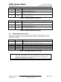
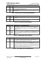
Setting
Label
1 to 2
out
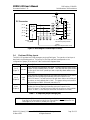
The data buffers are configured as “output” buffers (from the PC out through the
PMDX-122).
2 to 3
**
The data buffer direction is dynamically controlled by the pin 17 from the PC’s
parallel port. See section 3.1.4, Data Bus Buffer Direction, for more information.
See the note and warning in section 3.1.4.
Open
(jumper
not
installed)
Description
The data buffers are configured as “input” buffers (through the PMDX-122 into
the PC). See the note and warning in section 3.1.4.
Table 25 – Data Bus Direction Jumper Settings (JP5)
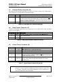
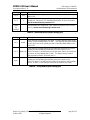
Setting
1 to 2
2 to 3
Open
Label
Description
normal
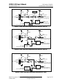
The E-Stop input is an emergency stop signal. The Fault input has a 100K pull-up
resistor so that its default state is “no fault”. The E-Stop and Fault inputs combine
to drive pin 10 into the PC parallel port and to optionally disable buffers on the
PMDX-122.
signal only
The E-Stop input is a general-purpose input and directly drives pin 10 on the PC
parallel port without affecting the data bus and control outputs on the
PMDX-122 board. The Fault input has a 10K pull-down resistor and a 100K pullup resistor so that its default state is “fault”. This jumper setting is used for
daisy-chaining two PMDX-122 boards, see 7.2.
The E-Stop input is a general-purpose input and directly drives pin 10 into the PC
parallel port without affecting the data bus and control outputs on the
PMDX-122 board. The Fault input has a 100K pull-up resistor so that its default
state is “no fault” (i.e. the Fault input can be left unconnected if not used).
Table 26 – E-Stop Mode Jumper Settings (JP6)
PMDX-122_Manual_112.doc
20 March 2013
©2005-2013, Practical Micro Design, Inc.
All Rights Reserved
Page 26 of 32