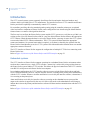
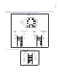
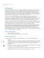
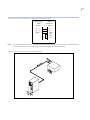
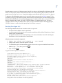
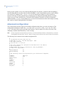
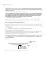
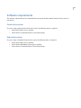
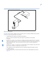
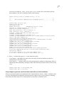
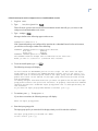
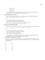
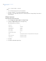
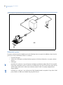
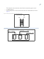
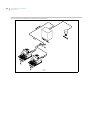
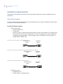
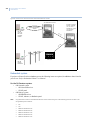
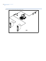
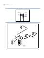
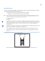
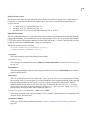
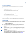
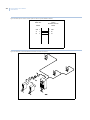
1
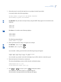
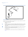
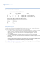
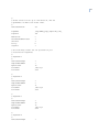
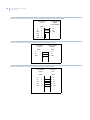
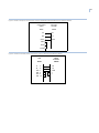
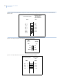
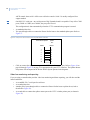
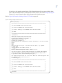
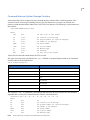
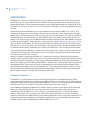
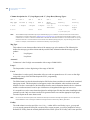
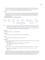
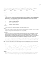
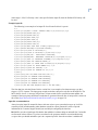
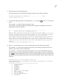
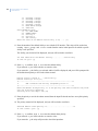
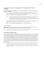
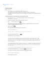
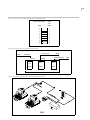
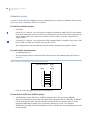
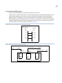
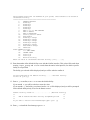
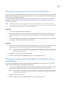
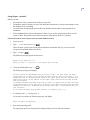
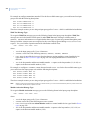
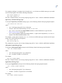
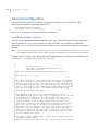
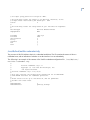
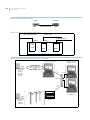
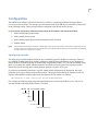
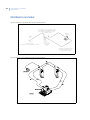
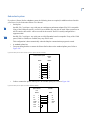
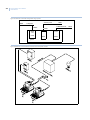
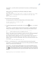
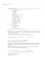
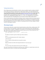
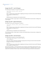
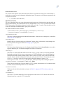
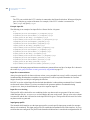
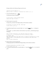
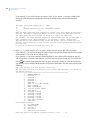
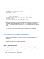
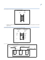
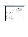
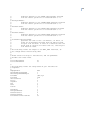
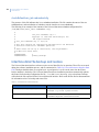
183
This configuration is done automatically when the Firesine communication program is started.
•
•
A standard splitter box
Two pass-through cables to connect the Picture Perfect hosts to the standard splitter ports. Refer to
Figure 61.
Figure 61. Cable pinouts: Picture Perfect system to splitter (DB25F to DB25M)
Picture Perfect System
DB25F
Splitter
Port
DB25M
1
1
2
2
3
3
4
4
5
5
7
7
8
8
20
20
Figure 62. Overview of the cable configuration using a splitter
DB9M
DB25F
To Primary Host
To Firepanel
DB25M
To Redundant Host
DB25M
DB25M
Master
Port
Port 1
Port 2
DB25F
DB25F
DB25F
Splitter
DB25F