1
RMS Compact II
User Manual
Version 1.0.2
th
11 August 2008
RMS Compact II
Conventions Used in this Manual
This manual uses the following typographic conventions:
Table 1-1.
Typographic Conventions
italics
bold
fixed
{somevalue}
<ctrl+alt+delete>
Items as seen on screen, field names, menu names, button text
etc.
Indicates items that require special emphasis.
Inputs by the user that must be typed exactly as they appear.
Italics surrounded by curly braces indicate a user supplied entry
that must be input. E.g.: {drive}:\setup
Text surrounded by angled brackets indicate specific keys to be
pressed. Use of the + sign in combination indicate that keys
should be pressed together.
Note!
Information of note may be presented like this.
Warning!
These messages alert you to specific procedures or
practices; serious consequences may result
including injury if you disregard them.
Version 1.0.2 August 2008
Page 2
RMS Compact II
About this Manual
This manual is intended to document the RMS Compact II product.
Throughout this document it is assumed that the user has a basic to intermediate
knowledge of IT and Networking concepts.
Further information regarding IT and Networking fundamentals may be found in the
appendices of this document.
Copyright 2008
Unauthorised reproduction prohibited.
Version 1.0.2 August 2008
Page 3
RMS Compact II
Table of Contents
Conventions Used in this Manual ................................................................... 2
About this Manual ............................................................................................ 3
1
Introduction .................................................................................................. 6
Overview .......................................................................................................... 6
2
RMS Compact II Package ........................................................................... 7
Package contents ............................................................................................ 7
Front of RMS Compact II MCU ....................................................................... 7
Rear of RMS Compact II MCU........................................................................ 8
Installation Requirements.............................................................................. 10
3
Initial Setup ................................................................................................ 11
Installation into a 19” rack ............................................................................. 11
Zero-U 19” rack installation ........................................................................... 12
Default Settings ............................................................................................. 14
Connecting to the Web Management Interface............................................ 14
Initial network setup....................................................................................... 19
4
Web Management Interface ...................................................................... 24
Network Setup - Overview ............................................................................ 24
Network Setup - IP Configuration ................................................................. 25
Network Setup - HTTP .................................................................................. 26
Network Setup – LDAP Servers ................................................................... 28
Network Setup - SNMP NMS ........................................................................ 30
Network Setup - SNMP Trap Receivers ....................................................... 31
Network Setup - Users .................................................................................. 32
Network Setup – Restart ............................................................................... 34
Input Sensors – Status .................................................................................. 35
Input Sensors – Defaults ............................................................................... 36
Input Sensors - Configure ............................................................................. 40
Relays – Status ............................................................................................. 42
Relays – Configure ........................................................................................ 43
Relays – Configure - Config .......................................................................... 45
5
LDAP .......................................................................................................... 47
RMS Compact II LDAP Overview ................................................................. 47
RMS Compact II LDAP Structure ................................................................. 47
6
Logic Configuration .................................................................................... 49
Configuration Example – Keypad activated door solenoid .......................... 49
7
Troubleshooting ......................................................................................... 50
Resetting RMS Compact II to factory default settings ................................. 50
The NMS Cannot poll the RMS Compact II.................................................. 50
8
Appendix A: Technical Details .................................................................. 51
Factory Default Settings ................................................................................ 51
Operating Information.................................................................................... 51
Version 1.0.2 August 2008
Page 4
RMS Compact II
9
Appendix B: Hysteresis Demystified ......................................................... 52
How Hysteresis works ................................................................................... 52
10
Appendix C: Networking Reference ...................................................... 54
Reference ...................................................................................................... 54
Version 1.0.2 August 2008
Page 5
RMS Compact II
1 Introduction
Overview
RMS Compact II is a low cost networkable zero-U rack monitoring device. The RMS
Compact II provides both SNMP and Web monitoring and management.
Some of the main features of the RMS Compact II unit are:
•
Modular design permits future expansion.
•
Secure web management and configuration interface.
•
SNMP enabled.
•
Twelve monitoring channels.
•
Optional LCD Status module.
Version 1.0.2 August 2008
Page 6
RMS Compact II
2 RMS Compact II Package
Package contents
The standard RMS Compact II package contains a RMS Compact II unit with
supporting hardware:
Table 2-1.
Package contents
RMS Compact II Master Control Unit.
12vDC 1000mA PSU
19” rack mounting kit.
‘Zero U’ mounting bracket
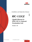
Front of RMS Compact II MCU
The following images show the font and rear panels of the RMS Compact II Master
Control Unit (MCU):
Figure 2-1.
Front of RMS Compact II MCU.
LEDs
Five LEDs can be found on the front of the RMS Compact II MCU. Their purpose is
described below.
Version 1.0.2 August 2008
Page 7
RMS Compact II
Network Link:
Illuminates when Ethernet link is established and flashes with
data.
Network Speed:
Illuminates when Fast Ethernet is active (100mbps).
Status:
Indicates system activity.
Alarm:
Illuminates when there is an alarm present on the unit.
Power:
Illuminates when unit is powered.
Buttons
Also found on the front of the RMS Compact II MCU are two buttons, their functions
are described below.
Reset:
Allows the user to reboot the unit.
Mode:
The mode select switch is used to reset the unit to factory
defaults. See the Troubleshooting section for details.
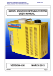
Rear of RMS Compact II MCU
Figure 2-2
Rear of RMS Compact II MCU.
Power Inlet:
Power inlet supporting 12 Volts DC.
DC Relay (Relay 1):
Output rated 48VDC/VAC @ 750mA Presented on
Screw-Lock Weidmuller connector
Version 1.0.2 August 2008
Page 8
RMS Compact II
AC Relays (2-3):
Sensor Inputs
(twelve):
Network
Connector:
Outputs rated 240VAC @ 3A presented on Screw-lock Phoenix
Type connector
Twelve sensor inputs are provided for connection of external
contacts, temperature and humidity sensors.
An RJ-45 connection provides Ethernet and Fast Ethernet
connectivity to the RMS Compact II MCU.
Version 1.0.2 August 2008
Page 9
RMS Compact II
Installation Requirements
•
RMS Compact II Master Control Unit (MCU).
•
100 – 240V AC Power supply
•
Ethernet or Fast Ethernet network connection.
•
Network connected computer system to setup the RMS Compact II MCU.
Version 1.0.2 August 2008
Page 10
RMS Compact II
3 Initial Setup
Installation into a 19” rack
There are two ways of mounting RMS Compact II into a 19” rack system. The first is
in the standard horizontal 19” rack configuration.
Using the 1U Adapter Brackets
The unit can be mounted in the rack as a standard 1U unit, using the supplied adapter
brackets. The fitting instructions are shown below:
Step One – Fit cage nuts
Figure 3-1.
Fit cage nuts (not supplied).
Version 1.0.2 August 2008
Page 11
RMS Compact II
Step Two – Attach mounting brackets
Figure 3-2.
Attach supplied 19" mounting brackets.
1U mounting brackets are attached as above using 4 screws (supplied).
Step Three – Screw RMS Compact II into rack
Figure 3-3.
Screw RMS Compact II into rack.
Step Four– Make connections
Connect Power, Ethernet connection, Relay Output and sensor cables
Zero-U 19” rack installation
The second method of installing the RMS Compact II MCU into a 19” rack is the
Zero-U option.
The provided Zero-U rack mount bracket allows the unit to be placed in the vertical
position at the side of a rack.
Warning!
The RMS Compact II unit must not be mounted
horizontally using the Zero-U bracket. Mounting in this
way may damage the unit.
Version 1.0.2 August 2008
Page 12
RMS Compact II
Figure 3-4.
RMS Compact II with zero U mounting bracket attached for vertical
mounting
Version 1.0.2 August 2008
Page 13
RMS Compact II
Default Settings
The RMS Compact II unit in factory default condition will have the following
network configuration. Advanced users may wish to make use of these settings to
access the RMS Compact II units web management interface immediately and
proceed with configuration.
Users who do not know how to do this should proceed through this chapter for
information on how to configure the RMS Compact II unit.
Table 3-1.
RMS Compact II Defaults
IP Address:
Subnet Mask:
Default Gateway:
Web Management Address:
Default username:
Default password
Note!
192.168.0.253
255.255.255.0
192.168.0.1
http://192.168.0.253/
admin
admin
Password entries are case sensitive!
Connecting to the Web Management Interface
The RMS Compact II monitoring solution can be configured entirely using the built in
web management interface.
In order to connect to the web management interface for the first time the IP address
of the PC to be used may need to be changed.
This section will detail how to connect to change the IP address and connect to the
web management interface.
Version 1.0.2 August 2008
Page 14
RMS Compact II
Changing your PCs IP address
Note!
Instructions refer specifically to Windows XP
Professional. Please refer to your operating system
documentation if you are not using Windows XP
Professional.
1) On Windows XP Start menu <Right Click> on My Network Places then right
click on Properties. This can be seen in Figure 3-4. My Network Places.
Figure 3-4.
My Network Places
2) The Network Connections window will appear as shown in Figure 3-5.
Network Connections window
Version 1.0.2 August 2008
Page 15
RMS Compact II
Figure 3-5.
Network Connections window
3) <Right Click> on Local Area Connection and click on Properties. This will
open the Local Area Connection Properties window as shown in Figure 3-6.
Local Area Connection Properties window.
Version 1.0.2 August 2008
Page 16
RMS Compact II
Figure 3-6.
Local Area Connection Properties window.
4) Select Internet Protocol (TCP/IP) (you may need to scroll down). Click the
Properties button.
5) Select Use the following IP address and Use the following DNS server
addresses radio buttons. Proceed to enter the following details into the
appropriate boxes. (This can be seen in Figure 3-7. Internet Protocol
(TCP/IP) Properties screen)
IP address:
Subnet mask:
Default gateway:
192.168.0.10
255.255.255.0
192.168.0.1
Preferred DNS server:
192.168.0.1
Click OK to accept the entries.
Version 1.0.2 August 2008
Page 17
RMS Compact II
Figure 3-7.
Internet Protocol (TCP/IP) Properties screen
6) On the Local Area Connection Properties Click OK to return to the desktop.
Congratulations you have just changed your IP address and can now proceed with the
next stage of the RMS Compact II Rack Monitor setup.
Connecting to the web management interface
1) Connect the RMS Compact II MCUs network connection directly to a PCs
Ethernet network card using a crossover cable.
Note!
A crossover cable must be used when directly
connected the RMS Compact II MCU to a PCs network
card.
2) Power the RMS Compact II unit.
3) Open a web browser.
4) Enter into the address bar http://192.168.0.253
Version 1.0.2 August 2008
Page 18
RMS Compact II
5) The Web Management Interface will now load.
Figure 3-8.
Web Management Interface login screen.
6) Click login and enter the username and password. The unit defaults are:Default username:
Default password
Table 3-2.
Note!
admin
admin
Default Passwords.
Password entries are case sensitive!
Initial network setup
This section provides details on preparing the unit for network access and allowing
SNMP network management.
Connection to the web management interface is required.
Entering NMS details
1) Click the Network Setup tab on the top menu bar then select the SNMP NMS
button found on the left menu bar.
Version 1.0.2 August 2008
Page 19
RMS Compact II
Figure 3-9. SNMP NMS Setup.
2) Input the IP address, chosen community string and required NMS access
permissions of the Network Management Stations to be used.
3) Click Save to confirm the changes.
4) To disable an NMS the Disabled entry should be selected from the NMS
Access drop down list.
Version 1.0.2 August 2008
Page 20
RMS Compact II
Entering Trap Receiver details
1) Click the Network Setup tab on the top menu bar then select the SNMP
Rec’rs button found on the left menu bar.
Figure 3-10.
Trap Receivers setup
2) The IP address, chosen community string and required trap types should be
entered for the Network Management Stations to be used.
3) Click Save to confirm the changes.
Version 1.0.2 August 2008
Page 21
RMS Compact II
Adding users
1) Click the Network Setup tab on the top menu bar then select the Users
button found on the left menu bar.
Figure 3-11.
User menu
2) Usernames, passwords and access levels can be set here. Unique usernames
can be set for individuals who require web management access to the RMS
Compact II unit.
3) Click Save to confirm the changes.
Version 1.0.2 August 2008
Page 22
RMS Compact II
Changing the unit IP address
1) Click the Network Setup tab on the top menu bar then select the Users
button found on the left menu bar.
Figure 3-12.
IP Configuration
2) The IP address, subnet mask and gateway that the RMS Compact II will use
must be entered here.
Contact your network adminstrator if you do not know the values that you
must enter here.
3) Click Save to confirm the changes.
4) Click Restart and select Restart Now to reboot the unit and bring the changes
into effect.
Note!
Once the IP configuration has changed the RMS
Compact II unit will no longer be accessible via the
default IP address as the new address will be
operational.
5) The RMS Compact II unit should now be connected to the main network and
any further required configuration done via the units new IP address.
Version 1.0.2 August 2008
Page 23
RMS Compact II
4 Web Management Interface
The RMS Compact II unit has a built in Web Management interface which can be
accessed securely. The interface permits complete configuration and monitoring of the
RMS Compact II unit.
Pages where changes can be made have a Save button in the lower right hand area.
This must be pressed to action and save any changes made.
Network Setup - Overview
The Overview page is the first page displayed and provides the user with an overview
of the RMS Compact II units’ current status.
Figure 4-1.
Overview screen.
System name, MAC address, serial number, firmware version and a selection of other
system details can be found here.
Version 1.0.2 August 2008
Page 24
RMS Compact II
Network Setup - IP Configuration
The IP Config page permits setting of the RMS Compact II units own management IP
address.
Figure 4-2.
IP Configuration
System Name
System name may be specified here. This would normally be the fully qualified
domain name (FQDN) of the device but this is not enforced.
The value specified here can be retrieved by interrogating the ‘sysName’ node via
SNMP.
This allows SNMP management platforms to obtain unique names for units where
specified.
This value has no effect on network communications and the unit will function
correctly with or without a value.
IP Address
A standard IP address may be entered here. The address is entered in dotted decimal
format.
Eg: 192.168.0.44 or 22.10.45.33
The address entered here will be the address by which the RMS Compact II unit is
accessed and managed.
Version 1.0.2 August 2008
Page 25
RMS Compact II
Subnet Mask
The subnet mask is used to determine what part of the IP address is the network
portion and what part is the host portion.
It is often 255.255.0.0 or 255.255.255.0 however correct setting is essential for correct
operation.
The subnet mask is entered in dotted decimal format.
Eg: 255.255.255.0 or 255.255.224.0
Gateway
The gateway setting specifies the IP address of the machine/router which the RMS
Compact II unit uses to communicate with different networks.
The gateway address is entered in dotted decimal format.
Eg: 192.168.0.1 or 11.2.24.103
Most networks will have a gateway and correct setting is important for correct
network communications.
Note!
Once IP Configuration options are entered and Save is
pressed the changes will take effect. If incorrect
entries are made this may result in loss of
communication.
In this event the best course of action is to reset the
RMS Compact II units’ network configuration.
Details of how to do this can be found in the Troubleshooting section.
Network Setup - HTTP
Access method for the web management interface is selected here.
Both HTTP and HTTPS access modes are available by default. Selecting the HTTPS
radio button will allow only HTTPS configuration.
Use of HTTPS is recommended for security as connections will be encrypted.
Additionally the TCP port for connection to the Web Management Interface can be
specified here.
Version 1.0.2 August 2008
Page 26
RMS Compact II
Note!
Figure 4-3.
Selecting HTTP or HTTPS requires a reboot to take
effect.
HTTP Setup
Version 1.0.2 August 2008
Page 27
RMS Compact II
Network Setup – LDAP Servers
Lightweight Directory Access Protocol (LDAP) configuration options are specified
here.
See Section 5 LDAP (Page 47) for configuration details.
Figure 4-4.
LDAP Setup
Configuration options for a Primary and Secondary server are provided with identical
configuration choices offered.
Enabled
Disabled
No LDAP servers will be queried to verify user login credentials access and
privileges. Only internal users will be able to login.
Primary
Only the Primary LDAP Server specified will be queried to verify user login
credentials access and privileges.
Secondary
Only the Secondary LDAP Server specified will be queried to verify user login
credentials access and privileges.
Both
Both LDAP Servers specified will be queried (with priority given to the Primary) to
verify user login credentials access and privileges.
Version 1.0.2 August 2008
Page 28
RMS Compact II
Credential Cache
Specifies how long (in minutes) users successfully authenticated via LDAP will be
allowed to access the unit without re-authenticating against LDAP.
Display Name
A display name for the specified LDAP server can be specified here. Display Name is
for reference and logging purposes and has no direct affect on LDAP function.
IP Address
The IP address of the LDAP server is specified here.
Unit Base DN
The Distinguished Name (DN) of the directory object containing the RMS Compact II
LDAP authentication structure must be provided here. This field is required for LDAP
function.
See Section 5 LDAP (Page 47) for configuration details.
Users Base DN 1
The Distinguished Name (DN) of the directory object containing directory users for
authentication is specified here.
This field is required for LDAP function.
See Section 5 LDAP (Page 47) for configuration details.
Users Base DN 2
The Distinguished Name (DN) of the directory object containing directory users for
authentication is specified here.
This field is optional for LDAP function providing Users Base DN 1 has been
specified.
See Section 5 LDAP (Page 47) for configuration details.
Version 1.0.2 August 2008
Page 29
RMS Compact II
Network Setup - SNMP NMS
The IP address, community string and access permissions are specified here for up to
5 Network Management Stations.
Any machine which must access this unit’s SNMP functions must be entered here.
Figure 4-5.
SNMP NMS
IP Address
The IP address of the NMS machine should be entered here.
Community String
The required community string must be entered here. The default for many devices is
public.
It is recommended that the community string be changed as it is effectively an access
password.
NMS Access
Read Only access permits the NMS to use only GET commands.
Read / Write access permits the NMS to use both GET and SET commands.
Version 1.0.2 August 2008
Page 30
RMS Compact II
Network Setup - SNMP Trap Receivers
The IP address, community string and access permissions are specified here for up to
five Network Management Stations.
Figure 4-6.
SNMP Trap Receivers
IP Address
Any machine which will be required to receive SNMP traps sent from this unit must
be entered here. Usually any SNMP NMS entries should also be entered here.
Community String
The required community string must be entered here. The default for many devices is
public.
It is recommended that the community string be changed as it is effectively an access
password.
Receive Traps
Receive traps Enabled setting allows the specified NMS to receive the units standard
range of traps.
Receive traps Enabled (incl Auth fails), will cause the unit to issue traps if an
unauthorised IP address attempts to access the units SNMP functions.
Receive traps Disabled prevents traps from being sent to the specified NMS IP
address.
Version 1.0.2 August 2008
Page 31
RMS Compact II
Network Setup - Users
Users with permission to access the Web Management Interface can be added here.
Access passwords are also specified along with users access permissions.
Figure 4-7.
User Setup
Username
The required username is entered here. This is the username that will be required to
login to the Web Management Interface.
Password
Access passwords are entered here on a per user basis.
Level
Three user levels are available for assignment.
Administrator
Administrators have full control of RMS Compact II configuration settings.
Controller
Controllers are able to view configuration settings.
Viewer
Version 1.0.2 August 2008
Page 32
RMS Compact II
Viewers are able to view configuration settings.
Warning!
User 1 / admin is the master administrator. It is
possible to remove administrator rights from the
admin user. Doing this is not recommended as it may
leave you without administrator access.
In this situation a reset to factory defaults is the only solution.
Details on how to do this can be found in the Troubleshooting section.
Version 1.0.2 August 2008
Page 33
RMS Compact II
Network Setup – Restart
A unit may be rebooted or reset to factory defaults here.
Figure 4-8.
Restart
Restart Unit
Restart Now
Selecting ‘Restart Now’ commands the unit to reboot. A confirmation prompt is
displayed. Rebooting the unit will cause any outstanding configuration changes to
come into effect.
Factory Defaults
Reset to Factory Defaults
Selecting ‘Reset to Factory Defaults’ instructs the unit to restore factory default
settings. A prompt appears for confirmation.
Default IP address settings will not come into effect until the unit is rebooted.
This behaviour allows a user to reset a unit to defaults without losing
communications. The correct IP address can then be entered on the IP Setup page
before the unit is rebooted with the ‘Restart Now’ button.
Version 1.0.2 August 2008
Page 34
RMS Compact II
Input Sensors – Status
The Input Sensors status page presents an overview of the RMS Compact II input
ports.
Input channel number, name, type of input sensor, status, current readings and
thresholds can all be seen at a glance here.
Figure 4-9.
Input Sensor Status.
Status Indicators
Three status indicators are displayed next to input channels to allow quick
determination of normal, warning and critical alarm statuses:All thresholds within limits.
Upper or lower Warning limit reached/exceeded.
Upper or lower Warning limit reached/exceeded.
Table 4-1.
Input Status Indicators.
Version 1.0.2 August 2008
Page 35
RMS Compact II
Input Sensors – Defaults
The Input Sensor Defaults menu allows configuration parameters which relate to input
sensors of specific types to be defined and applied to all inputs of that type.
The types of input sensors are:Temperature
Humidity
Open/Close Contacts (digital inputs)
Figure 4-10.
Input Sensor Defaults with Temperature and Humidity menus.
The defaults than can be specified are described below.
Calibration Offset
The value entered here alters the actual reading of a sensor by the amount specified.
For example, if an Calibration offset of 6 was used and a sensors true reading was 36
the indicated reading used for display and alarm purposes would be 42.
This works in an identical way for both temperature and humidity sensors.
Hysteresis Value
The hysteresis default value to be applied to sensors is specified here. The value
specified is an offset from a sensors threshold values.
Version 1.0.2 August 2008
Page 36
RMS Compact II
For example, a hysteresis value of 5 would mean that in the case of an Upper Control
Limits alarm the alarm value would have to reduce to 5 below the threshold value
before another alarm is issued.
Please see Appendix B: Hysteresis Demystified for detailed information.
Limits and Traps
Defaults values for sensor alarm thresholds can be specified here. The default settings
for alarm threshold traps can also be specified here.
The thresholds than can be set are as follows:Upper Control Limit
Upper Warning Limit
Lower Warning Limit
Lower Control Limit
Default trap settings can also be applied for all of these thresholds. With the trap box
un-ticked no SNMP alarm traps will be generated even when an alarm condition
exists for that threshold.
Repeat Timer
The repeat timer causes alarm traps to be reissued after a specified amount of time if
the alarm condition remains present.
Setting the repeat timer to zero (0) will disable the repeat traps.
Version 1.0.2 August 2008
Page 37
RMS Compact II
Rising & Falling Rates of Change
If the rate of change of this value is exceeded, then a trap will be generated - i.e. if the
rate of change value is set to 1.0, then if the value read by the sensor goes from 22.0
degrees to 23.0 degrees within 1 minute, then a trap will be generated.
Figure 4-11.
Input Sensor Defaults with Open/Close Contacts menu.
The defaults that can be set for Open/Close contacts differ from the Temperature and
Humidity settings.
Normal State
Normal state specifies the condition in which a contact is considered to be ‘Normal’,
‘Non-alarmed’ state.
Devices such as smoke alarms and air conditioning units often have normally open
contacts. In order to receive alarm indications from these types of units setting
normally open would cause alarms to be issued when the monitored contact closes.
Setting normally closed in the case of a rack cabinet door would cause an alarm
condition when the door was opened.
Trigger Type
Trigger type defaults for Open/Close sensors are specified here.
The three available options for trigger types are:Level
Level triggering is the default mode. When an input physically transitions from a
Normal to Non-Normal state an alarm will be triggered. However the alarm will only
Version 1.0.2 August 2008
Page 38
RMS Compact II
persist whilst the input remains in a Non-Normal state. When the input returns to a
normal state the alarm will be cleared.
Normal to Non-Normal (Positive Edge)
This type of triggering may be used in situations where a momentary type input (eg:
shock sensor, PIR etc), is used. Since these types of inputs are momentary any alarm
condition which occurs no matter how short will persist until manually cleared.
Positive Edge triggering is used when an alarm is required to persist after an input
changes from the Normal state to the Non-Normal state.
Non-Normal to Normal (Negative Edge)
This type of triggering may be used in situations where a momentary type input (eg:
shock sensor, PIR etc), is used. Since these types of inputs are momentary any alarm
condition which occurs no matter how short will persist until manually cleared.
Negative Edge triggering is used when an alarm is required to persist after an input
changes from the Non-Normal to Normal state to the state.
Version 1.0.2 August 2008
Page 39
RMS Compact II
Input Sensors - Configure
Configure allows the individual sensor channels to be configured.
Figure 4-12.
Input Sensor Configuration
Figure 4-13.
Input Sensor Channel Configuration
Version 1.0.2 August 2008
Page 40
RMS Compact II
Selecting the Config option will open a detailed configuration page for the selected
sensor.
The important difference between the menus presented here and the menus presented
on the Defaults page is that settings are applied to individual channels.
The options found in the submenus are identical to those in the Defaults menu,
however two additional options can be found.
These are detailed below:Name
Sensor channels can be assigned names for ease of identification. Eg: “Server Room
Sensor”, “UPS Battery Fail”.
Type
The type of connected sensor is specified here. The sensor channels can be set to auto
detect, temperature, humidity, contact or disabled.
Version 1.0.2 August 2008
Page 41
RMS Compact II
Relays – Status
The Relay Status page provides an overview and direct control of the RMS Compact
II units 4 output relays.
Figure 4-14.
Relay Status
Control
Activate
Activate commands the selected relay to energise.
Deactivate
Deactivate commands the selected relay to de-energise.
Use Logic
Commands the selected relay into ‘Logic controlled’ mode. In logic controlled mode
the activation and deactivation is governed by any configured and enabled logic.
See Section 1 (Page 49) for further information and configuration examples.
Version 1.0.2 August 2008
Page 42
RMS Compact II
Relays – Configure
Relay and logic configuration is performed via two pages.
Figure 4-15.
Relay Configure
Name
Relay output name is specified here. (E.g. Fan_Tray or Door_1).
Normal State
Normal State specifies the ‘normal’ or ‘non-alarm’ state of a relay.
Not Active
Specifies that a output relay in a ‘Not Active’ (‘not-energised’) state is normal.
Active
Specifies that anoutput relay in an ‘Active’ (‘Energised’) state is normal.
Trap Enabled
Toggles alarm trap generation. An alarm trap will be generated when the relay is in an
‘alarm’ state with this enabled.
Repeat Timer
Specifies an interval in which a trap for an existing alarm condition will be
regenerated. This will be a duplicate of the original trap. A repeat timer is not
necessary in NMS systems employing intelligent trap handling. Setting zero (0)
disables repeat traps.
Version 1.0.2 August 2008
Page 43
RMS Compact II
Controlled
This toggle acts as a master control to any logic configured for a relay. When selected
Use Logic may be enabled on the Status page.
It is only possible to select this option if logic has been specified in the Relay
Specific Configuration page.
See Section 1 (Page 49) for further information and configuration examples.
Virtual Relays 4 – 18 (V)
Relays 4 -18 are virtual relays, i.e. there is no physical relay present (1-3 have an
actual relay that can be switched either manually or using the in-built Boolean login
capability). Virtual Relays 4 – 18 can be used for generating traps based on Boolean
logic calculations even though a physical relay is not present.
Version 1.0.2 August 2008
Page 44
RMS Compact II
Relays – Configure - Config
Actual Digital Output Relay logic configurations are specified here.
Figure 4-16.
Relay Specific Configuration
Input Selection
Inputs into the logic are selected on the left hand side by clicking one of the Click to
Enable boxes.
Here a sensor type, threshold and channel can be chosen to feed into logic.
Invert
The Invert checkbox allows the logic inversion of an input into the logic.
For example, an upper warning limit is breached, this yields the follow input into
logic.
Threshold breached
Threshold within limit
Table 4-2.
No Invert
1 (Logic Triggering)
0 (Not Logic Triggering)
Invert
0 (Not Logic Triggering)
1 (Logic Triggering)
Input Logic Inversion.
Logic Operator
Logic Operator provides options which control the evaluation of inputs to logic.
Logical AND Inputs
Version 1.0.2 August 2008
Page 45
RMS Compact II
Logical AND requires ALL of the selected inputs to the logic to be in a triggering
state to activate the relay logic.
Logical OR Inputs
Logical OR requires only ONE of the selected inputs to be in a triggering state to
activate the relay logic.
Delay Timer On
Specifies the time in seconds which must elapse before the logic activates in a
situation where it would otherwise activate immediately.
This is useful in a situation where you want a delay to be added before a logic
controlled relay is switched on.
If the logic triggering condition clears before the specified time has elapsed then the
logic will not activate at all.
Delay Timer Off
Specifies the time in seconds which must elapse before the logic deactivates in a
situation where it would otherwise deactivate immediately.
This is useful in a situation where you want a delay to be added before a logic
controlled relay is switched off from a current on state.
If the logic triggering condition returns before the specified time has elapsed then the
logic will not deactivate at all.
Final Invert
A final invert check box is provided. This allows the final output logical state to the
relay to be inverted.
Essentially, any conditions which produce a relay on output will produce the reverse
and vice versa.
See Section 1 (Page 49) for further information and configuration examples.
Version 1.0.2 August 2008
Page 46
RMS Compact II
5 LDAP
RMS Compact II LDAP Overview
The RMS Compact II implements a Lightweight Directory Access Protocol (LDAP)
client.
This allows the RMS Compact II unit to authenticate user logins to the Web
Management Interface (WMI) using an LDAP Directory.
If LDAP is used for authentication it is first consulted when a user attempts a login. If
the user is not found or access is denied by LDAP then the credentials are checked
against the RMS Compact II internal user list.
Note!
Configuration of LDAP is an advanced topic and
requires existing knowledge of LDAP function and
setup (or access to personnel who do).
RMS Compact II LDAP Structure
In order for a RMS Compact II unit to successfully authenticate a user for WMI login
it needs to be ‘pointed’ to a specific structure within a directory.
A unit is ‘pointed’ to this structure within a directory by specifying the Unit Base DN
on the Network Setup – LDAP page.
The following Organisational Units will need to be created:
RMSCompact2 (this can be named anything)
RMSCompact2Administrators
RMSCompact2Controllers
RMSCompact2Viewers
See Figure 5-1 (Page 48) for hierarchy details.
The following Groups will need to be created:
RMSCompact2AdminUsers
RMSCompact2ControlUsers
RMSCompact2ViewUsers
Note!
Groups referred to are groups as found in Active
Directory schema. However any implementation which
provides a group with a ‘members’ attribute may
function.
Version 1.0.2 August 2008
Page 47
RMS Compact II
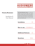
The following figure depicts the RMS Compact II LDAP authentication structure:
Hawki2
ORGANISATIONAL UNITS
Hawki2Administrators
Hawki2Controllers
Hawki2Viewers
Hawki2AdminUsers
Hawki2ControlUsers
Hawki2ViewUsers
Attribute
Member
Attribute
Member
Attribute
Member
GROUPS
Figure 5-1.
LDAP Structure Chart.
Once the required LDAP structure has been created the Distinguished Name (DN) of
users should be added to either:
RMSCompact2AdminUsers
RMSCompact2ControlUsers
RMSCompact2ViewUsers
Group Membership and Access Level
Membership of these groups grants the following permissions on RMS Compact II
units:
RMSCompact2AdminUsers
Users placed into this group will have Admin privileges on RMS Compact II units.
RMSCompact2ControlUsers
Users placed into this group will have Controller privileges on RMS Compact II units.
Version 1.0.2 August 2008
Page 48
RMS Compact II
RMSCompact2ViewUsers
Users placed into this group will have View privileges on RMS Compact II units.
RMS Compact II Unit Configuration
For LDAP authentication to function each RMS Compact II unit requires certain
configuration values to be provided.
Figure 5-2.
LDAP Setup
The normal steps are listed below:
1) If one LDAP server is to be used select Enabled – Primary.
2) Enter a descriptive name, E.g: AD_Server_1 into Display Name.
3) Enter the complete DN of the top level OU as seen in Figure 5-1 above.
4) Enter the DN of where users that are members of RMS Compact II access
groups can be found in the Directory. These DNs can be entered into User
Base DN 1 and User Base DN 2.
5) Finally Save should be clicked to bring any changes into effect.
Version 1.0.2 August 2008
Page 49
RMS Compact II
6 Troubleshooting
Resetting RMS Compact II to factory default settings
To reset the RMS Compact II unit to factory default perform the following steps:
1) Power the RMS Compact II and wait for the Status LED (Green) to illumnate.
2) As soon as the Status LED illuminates press and hold the Mode button for
10 seconds.
3) When the Digital Output (Yellow), Analogue Input (Red) and Digital Input
(Red) lights extinguish release the Mode button.
4) Wait 90 seconds for the reset to complete.
The factory default settings will have been restored.
Note!
This process can be aborted by releasing the mode
switch before the Digital Output, Analogue Input and
Digital Input lights extinguish.
The NMS Cannot poll the RMS Compact II
Problem:
The NMS cannot ping or poll the RMS Compact II.
Solution:
good.
Make sure the network connection to the RMS Compact II is
Solution:
Make sure the cable is in good condition.
Solution:
Try pinging the RMS Compact II from another computer on the
same network segment as the RMS Compact II.
Solution:
Ensure that the NMS IP Address is in the NMS table of the
RMS Compact II.
Solution:
Ensure that the community string has been set for the NMS via
the web management interface.
Version 1.0.2 August 2008
Page 50
RMS Compact II
7 Appendix A: Technical Details
Factory Default Settings
Table 7-1.
RMS Compact II Defaults
IP Address:
Subnet Mask:
Default Gateway:
Web Management Address:
Default username:
Default password
192.168.0.253
255.255.255.0 (/24)
192.168.0.1
http://192.168.0.253/
admin
admin
Operating Information
Input Power:
Operating Temperature:
Storage Temeperature:
Operating Humidity:
Storage Humidity:
12VDC (300mA ~ 500mA)
0OC to 40 OC
-10 OC to 70 OC
5% to 90% RH
5% to 100% RH
Version 1.0.2 August 2008
Page 51
RMS Compact II
8 Appendix B: Hysteresis
Demystified
How Hysteresis works
When a temperature or humidity limit is reached and the relevant limit has its ‘OFF to
ON Trap’ enabled an alarm trap will be issued by the RMS Compact II for this event.
With a zero hysteresis setting the traps will continue to be generated each time the
limit is reached.
This may be undesirable in a situation where the temperature or humidity level
measure has only reduced by a small amount before rising again and triggering further
traps.
The hysteresis function is provided to prevent further alarm traps from being
generated until the measured value has fallen to a satisfactory level.
Alarm Trap
No Traps
Alarm Trap
Upper Limit
(25.0)
Hysteresis
Threshold
(23.5)
Figure 8-1.
Normal Trap
Hysteresis chart
As shown in the humidity first rises past its upper warning threshold which generates
a trap.
The humidity then reduces slightly but does not reduce to the hysteresis level which is
1.5% RH lower than the alarm (1.5% RH lower as an absolute measured value rather
than 1.5% of currently measured value).
Humidity then increases and decreases again. However on the second decrease of
humidity the level drops below the hysteresis level. The
Version 1.0.2 August 2008
Page 52
RMS Compact II
Humidity falling below the hysteresis level re-enables alarm traps for the next alarm
event. An upper limit of 25 and a hysteresis threshold of 1.5 yield a threshold limit of
23.5.
The humidity level again beings to rise and again exceeds the upper limit, however
this time an alarm trap is again generated.
The Hysteresis feature acts on the following Temperature and Humidity thresholds:•
•
•
•
Upper Control Limit (UCL)
Lower Control Limit (LCL)
Upper Warning Limit (UWL)
Lower Warning Limit (LWL)
The inverse of the above description is true when applied to Temperature and
Humidity lower control and warning limits.
As stated above the hysteresis threshold is user configurable using the menu options
detailed previously.
Version 1.0.2 August 2008
Page 53
RMS Compact II
9 Appendix C: Networking Reference
This appendix has two sections: Reference and Troubleshooting.
Reference
This section discusses SNMP communities, IP addressing, subnet masking, routers
and gateways.
Communities
A community is a string of printable ASCII characters that identifies a user group
with the same access privileges. For example, a common community name is
“public”.
For security purposes, the SNMP agent validates requests before responding. The
agent can be configured so that only managers that are members of a community can
send requests and receive responses from a particular community.
This prevents unauthorized managers from viewing or changing the configuration of a
device.
IP Addresses
Every device on an internetwork must be assigned a unique IP (Internet Protocol)
address. An IP address is a 32-bit value comprised of a network ID and a host ID.
The network ID identifies the logical network to which a particular device belongs.
The host ID identifies the particular device within the logical network.
IP addresses distinguish devices on an internetwork from one another so that IP
packets are properly transmitted.
IP addresses appear in dotted decimal (rather than in binary) notation. Dotted decimal
notation divides the 32-bit value into four 8-bit groups, or octets, and separates each
octet with a period.
For example, 199.217.132.1 is an IP address in dotted decimal notation.
To accommodate networks of different sizes, the IP address has three divisions Classes A for large, B for medium, and C for small.
The difference among the network classes is the number of octets reserved for the
network ID and the number of octets reserved for the host ID:
Version 1.0.2 August 2008
Page 54
RMS Compact II
Class
Value of Network ID
First Octet
1-126
first octet
A
B
128-191
C
192-223
Host ID
last three
octets
first two oc- last two octets
tets
first three
last octet
octets
Number of
Hosts
16,387,064
64,516
254
Any value between 0 and 255 is valid as a host ID octet except for those values
reserved by the IPv4 standard for other purposes:
Value
0, 255
127
224-254
Purpose
Network Number & Broadcast
Loopback testing and interprocess communication on local devices
IGMP multicast and other special protocols
Subnetting and Subnet Masks
Subnetting divides a network address into subnetwork addresses to accommodate
more than one physical network on a logical network.
For example: A Class B company has 100 LANs (Local Area Networks) with 100 to
200 nodes on each LAN.
To classify the nodes by its LANs on one main network, this company segments the
network address into 100 subnetwork addresses (If the Class B network address is
150.1.x.x, the address can be segmented further from 150.1.1.x through 150.1.100.x.).
A subnet mask is a 32-bit value that distinguishes the network ID from the host ID for
different subnetworks on the same logical network.
Like IP addresses, subnet masks consist of four octets in dotted decimal notation.
You can use subnet masks to route and filter the transmission of IP packets among
your subnetworks.
The value “255” is assigned to octets that belong to the network ID, and the value “0”
is assigned to octets that belong to the host ID.
Network Mask
255.0.0.0
Routing and Filtering
Class A network. First octet defines
network number. Final three octets
define host address. Valid Class A
Version 1.0.2 August 2008
Page 55
RMS Compact II
255.255.0.0
255.255.255.0
network numbers are in the range 1
to 126.
Class B network. First 2 octets
define network number. Final two
octets define host address. Valid
class B network numbers are in the
range 128.0.x.x to 191.255.x.x
Class C network. First 3 octects
define network number. Final octet
defines host address Valid class C
network numbers are in the range.
192.0.0.x 223.255.255.x
Gateways
Gateway, also sometimes referred to as a router, is any device with two or more
network adapters connecting to different physical networks.
Gateways allow for transmission of IP packets between different networks on an
internetwork.
Version 1.0.2 August 2008
Page 56