1
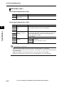
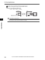
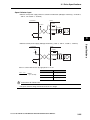
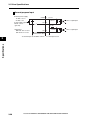
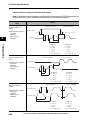
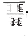
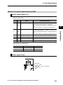
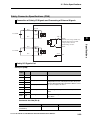
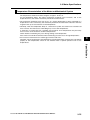
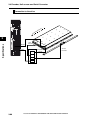
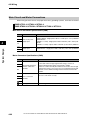
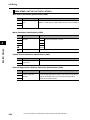
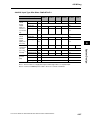
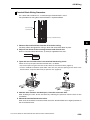
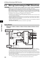
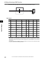
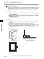
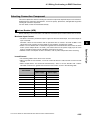
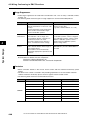
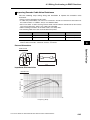
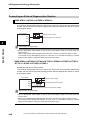
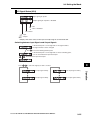
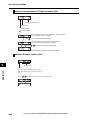
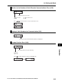
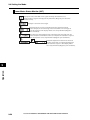
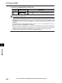
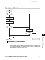
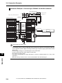
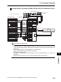
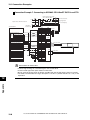
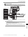
4-3 Wiring Conforming to EMC Directives Improving Control I/O Signal Noise Resistance Positioning can be affected and I/O signal errors can occur if control I/O is influenced by noise. Use completely separate power supplies for the control power supply (especially 24 VDC) and the external operation power supply. In particular, do not connect the 2 power supply ground wires. Install a noise filter on the primary side of the control power supply. If 24V DC supply brakes are being used, do not use the same 24-VDC power supply for both the brakes and the control I/O. Additionally, do not connect the ground wires. Connecting the ground wires may cause I/O signal errors. Keep the power supply for pulse commands and error counter reset input lines separated from the control power supply as far as possible. In particular, do not connect the 2 power supply ground wires. We recommend using line drives for the pulse command and error counter reset outputs. Always use twisted-pair shielded cable for the pulse command and error counter reset signal lines, and connect both ends of the shield cable to frame grounds. If the control power supply wiring is long, noise resistance can be improved by adding 1-F laminated ceramic capacitors between the control power supply and ground at the drive input section or the controller output section. For open collector specifications, keep the length of wires to within 2 m. System Design 4 4-42 Accurax G5-LINEAR AC SERVOMOTOR AND SERVO DRIVE USER'S MANUAL