1
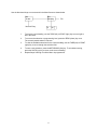
Digital Weight Indicator
Setup / Operation Manual
Revision 1.0
July 8, 2009
i
TABLE OF CONTENTS
Page
INTRODUCTION ........................................................................................................................................................... 1
FCC NOTE .................................................................................................................................................................... 1
INSTALLATION ............................................................................................................................................................. 1
PREPARATION......................................................................................................................................................... 1
CONNECTIONS ........................................................................................................................................................ 2
CONNECTING THE WEIGH PLATFORM................................................................................................................. 2
CONNECTING THE SERIAL I/O DEVICE ................................................................................................................ 2
CONNECTING THE POWER SUPPLY..................................................................................................................... 3
CONFIGURATION ........................................................................................................................................................ 3
OVERVIEW ............................................................................................................................................................... 3
ACCESSING THE MENUS ....................................................................................................................................... 3
MENU STRUCTURE................................................................................................................................................. 3
SETUP MENU DESCRIPTIONS ............................................................................................................................... 5
SETUP MENU PROCEDURES................................................................................................................................. 7
USER MENU DESCRIPTIONS ................................................................................................................................. 8
USER MENU PROCEDURES................................................................................................................................... 9
EXITING THE MENUS .............................................................................................................................................. 9
CALIBRATION ............................................................................................................................................................ 10
CALIBRATION OVERVIEW .................................................................................................................................... 10
ZERO CALIBRATION (F16) .................................................................................................................................... 10
SPAN CALIBRATION (F17) .................................................................................................................................... 10
VIEW CALIBRATION VALUES (F18)...................................................................................................................... 11
KEY-IN ZERO CALIBRATION VALUE (F19) .......................................................................................................... 12
KEY-IN SPAN CALIBRATION VALUE (F20)........................................................................................................... 12
OPERATION ............................................................................................................................................................... 13
DISPLAY ................................................................................................................................................................. 13
KEYBOARD............................................................................................................................................................. 13
FUNCTION KEYS ............................................................................................................................................... 14
GENERAL SCALE OPERATION............................................................................................................................. 14
WEIGHING AN ITEM .......................................................................................................................................... 14
PIECE COUNTING MODE .................................................................................................................................. 14
PEAK HOLD MODE ............................................................................................................................................ 15
REMOTE DISPLAY MODE ................................................................................................................................. 15
LEGAL FOR TRADE SEALING................................................................................................................................... 16
APPENDIX A: SPECIFICATIONS ............................................................................................................................... 17
APPENDIX B: SERIAL PORT INFORMATION ........................................................................................................... 18
SERIAL PORT MODES........................................................................................................................................... 18
DEMAND DUPLEX MODE .................................................................................................................................. 18
CONTINUOUS DUPLEX MODE ......................................................................................................................... 18
AUTO PRINT MODE ........................................................................................................................................... 18
OUTPUT STRINGS................................................................................................................................................. 19
TEXT PRINT TICKET.......................................................................................................................................... 19
STRING FORMAT 1 (Condec Demand String) ................................................................................................... 19
STRING FORMAT 2 (Condec Continuous String)............................................................................................... 19
APPENDIX C: DISPLAYED ERROR CODES ............................................................................................................. 20
©Totalcomp, Inc. 2009. All rights reserved.
The information contained herein is the property of Totalcomp and is supplied without liability for errors or omissions. No part may be
reproduced or used except as authorized by contract or other written permission. The copyright and the foregoing restriction on
reproduction and use extend to all media in which the information may be embodied.
Contents subject to change without notice.
13-01 Pollitt Drive Fair Lawn, NJ 07410
Tel (800) 631-0347 Fax (888) 797-2288
http://www.totalcomp.com/
ii
INTRODUCTION
The T500ESS Digital Indicator is a general purpose, industrial grade weight indicator. One model is
currently available, distinguishable by display type, enclosure type and power supply. Table 1 shows the
T500ESS product matrix.
This model can readout up to 50,000 display divisions and can supply enough current for up to 4-350
load cells. All setup parameters may be entered via the front panel keys, including calibration.
If your Model T500ESS Digital Indicator is part of a complete floor scale or has already been installed for
you, you may skip to the operating instructions. Prior to using the indicator, please read this chapter
carefully and completely. Store the manual in a safe and convenient place so it will be available if you
have questions concerning the operation of the scale.
MODEL
T500ESS
DISPLAY
TYPE
ENCLOSURE
TYPE
LED
Stainless Steel
POWER SOURCE
100-240 VAC, 50/60 Hz 30W
TABLE 1: T500ESS Series Product Matrix
FCC NOTE
This equipment has been tested and found to comply with the limits for a Class A digital device, pursuant
to Subpart J of Part 15 of the FCC Rules. These limits are designed to provide reasonable protection
against harmful interference when the equipment is operated in a commercial environment. This
equipment generates, uses and can radiate radio frequency energy and, if not installed and used in
accordance with the instructions manual, may cause harmful interference to radio communications.
Operation of this equipment in a residential area is likely to cause harmful interference in which case the
user will be required to correct the interference at his/her own expense.
INSTALLATION
PREPARATION
Any precision instrument requires a suitable environment in which to operate as intended. Please review
each of the following prior to installation:
Electrical Power
The T500ESS indicator has been designed to operate from 100 to 240 VAC at 50/60 Hz. All units ship
with the appropriate power plug for its area of intended use.
To avoid electrical noise interference and/or stray AC electrical transients, try to operate the indicator
from a circuit separate from any equipment containing inductive devices such as a contactor coil,
solenoid, relay coil, or motor. Be sure to use shielded cables for the load cell connections (ground shield
wire at indicator) and run these cables away from your AC/DC power cables if possible.
In extreme cases, it may be necessary to install surge suppressors, line conditioners or even UPS
(Uninterruptible Power Supplies) systems (not included).
1
Environment
-
Avoid installing the indicator in areas of direct sunlight or high humidity
Avoid sudden temperature change – if this is unavoidable allow equipment to ‘soak’ at a constant
temperature for at least three hours before use
Ensure that steady, clean AC power is available to the unit
Remember that the installer is ultimately responsible to assure that a particular
installation will be and remain safe and operable under the specific conditions
encountered.
CONNECTIONS
The rear cover must first be removed to make the appropriate connections to the weigh platform, printer,
remote display and power supply. To remove the rear cover, simply remove the screws that secure it to
the enclosure and set aside.
Caution! Disconnect power source from indicator prior to removing rear cover.
CONNECTING THE WEIGH PLATFORM
The TI-500E-SS indicator contains a connection terminal on the main board for connection to the load cell
cable. Connect your shielded load cell cable (not included) to the appropriate terminal on the main board.
NOTE: 6-wire connection is optional.
Load Cell Connector J4
Pin No.
1
2
3
4
Wire Name
Shield
- Signal
+ Signal
- Sense
Pin No.
5
6
7
Wire Name
- Excitation
+ Sense
+ Excitation
CONNECTING THE SERIAL I/O DEVICE
The T500ESS model comes standard with one full duplex RS-232 serial port, designed for connection to
a computer or a serial printer. The same port may be also used as a simplex, RS-232 port designed for
connection to a remote display.
Connection assignments for all serial RS-232 communication terminals on the TI-500E-SS are shown
below.
RS-232 Connector J3
Pin No.
1
2
3
Wire Name
TXD
RXD
RTS
Pin No.
4
5
2
Wire Name
CTS
Ground
CONNECTING THE POWER SUPPLY
The TI-500E-SS indicator ships with an AC line cord attached to the indicator. Simply plug the unit into a
standard wall outlet.
CONFIGURATION
OVERVIEW
The indicator contains two main configuration menus:
The Setup (“F”) menu, which configures the indicator to your weigh platform
The User (“A”) menu, which configures the serial communication port and enables some user
options
The Setup and User menus consist of several menu selections, each with its own sub-menu of selections
or programming procedures. To configure the indicator you must first enter the appropriate menu mode.
Once there, four of the front panel keys become directional navigators to move around in the menus, and
one key is used to save or SET the selections.
ACCESSING THE MENUS
To access the Setup (“F) menu:
1. Power off the indicator.
2. Locate the slide switch on the rear cover and move it to the opposite position.
NOTE: A metal plate held on by two drilled-head screws may conceal the slide switch.
3. Power on the indicator.
The display shows ” F 1” to indicate that you are in Setup Menu mode.
4. Use the navigation keys shown in the figure below to move through the menu.
To access the User (“A) menu:
1. Enter the Setup (“F”) menu.
2. Use the right or left directional keys shown below to move right or left in the Setup (“F”) menu
until the indicator shows ” A 1”.
SETUP MODE KEY FUNCTIONS
UNITS
ZERO
NET
GROSS
TARE
PRINT
SET
MENU STRUCTURE
All menus consist of a top level (heading) and a secondary level. The top level contains the code (e.g. F1)
for the parameter to be configured. The secondary level contains the selection list or allows access to a
programming sequence.
3
Use the directional keys to move around in the Menu Structure shown below.
F1
Grads
Numeric Entry
F2
Sampling
10
Etc.
80
1.
To move to a new heading, use the TARE (left) or PRINT (right) key to move right or
left in the Menu.
2.
To move to the selection or programming level, press the ZERO (down) key once.
The currently saved selection is shown.
3.
To view the available selections for the current heading, use the TARE (left) or PRINT
(right) key to move through the selection field.
4.
To save a new selection, press the NET/GROSS (Set) key .To exit without saving,
press the UNITS (up) key to return to the current heading.
5.
Repeat Steps 2 through 5 until the Menu is programmed.
4
SETUP MENU DESCRIPTIONS
This section provides more detailed descriptions of the selections found in the Setup Menu Chart.
Factory-set defaults are shown in bold; (NA) for North America and (€) for Europe.
NOTE: Some selections are subject to local legal metrology regulations
CODE/NAME
DESCRIPTION
SELECTION LIST
F1
Graduations
Specifies number of full-scale graduations, i.e. capacity / division.
Value should be consistent with legal regulations and environmental
limits on the useful system resolution. Pressing the ZERO key to
scroll down one level begins the sequence
Key-in
100 - 50000
5000 (NA)
3000 (€)
F2
Sampling Rate
Sets the sampling rate in Hertz (measurements per second). Use
10 Hz for most applications or 80 Hz for extra fast response time
10 (NA/€) 80
F3
Zero Track
Band
Selects the range within which the scale will automatically zero. Note
that the scale must be in standstill to automatically zero. Selections
are in display divisions (d).
0d
0.5d (NA/€)
1d
3d
5d
F4
Zero Range
Selects the range (expressed as a percentage of full scale capacity)
within which the scale may be zeroed. Note that the indicator must be
in standstill to zero the scale.
100% (NA)
1.9%
2% (€)
20%
F5
Motion Band
Sets the level at which motion is detected. If motion is not detected,
the scale can process a Print or Zero command. Maximum value
varies depending on local regulations. Expressed as scale divisions
per second (d/s). Pressing the ZERO key to scroll down one level
begins the sequence
Key-in
0.0d/s – 32.0d/s
Averages weight readings to produce higher stability. Choose the
speed that works best for your application.
FAST
nnEd (NA/€)
SLo
F6
Digital Filter
“FAST” = Fast
F7
Overload Limit
“nnEd” = Medium
“SLo” = Slow
Selects the desired formula which determines the point at which the
indicator shows overload. All selections are based on the primary unit
selected in F8.
"FS" = Full scale capacity.
1.0d/s (NA/€)
FS
FS + 2% (NA)
FS + 5%
FS + 1d
FS + 9d (€)
F8
Calib. Unit
Selects the primary base unit to be used in the calibration process.
Also the default unit for normal operation.
"1" = primary unit is lb.
"2" = primary unit is in kg.
1 (NA)
2 (€)
F9
Display
Divisions
Determines the desired weight increments. Value should be
consistent with legal requirements.
1 (NA)
2
5 (€)
F10
Decimal Pt.
Determines location of the decimal point.
0 (NA)
0.00
0.0000
5
0.0 (€)
0.000
00
CODE/NAME
F14
Units
Conversion
DESCRIPTION
Allows the lb/kg key to be disabled so that an operator cannot
accidentally press the key and change the displayed units.
SELECTION LIST
0 (€)
1 (NA)
"0" = Disable the Units key
"1" = Enable the Units key
F16
Zero
Calibration
Places indicator into the zero calibration routine. Scrolling down with
the ZERO key one level begins the procedure.
Press ZERO key
to begin sequence
F17
Span
Calibration
Places indicator into the span calibration routine. Scrolling down with
the ZERO key one level begins the procedure.
Press ZERO key
to begin sequence
F18
View
Calibration
Actuates the function that allows you to view both the zero and span
calibration value. The values displayed in this function are valid only
after Calibration (F16 & F17) has been successfully completed.
Scrolling down with the ZERO key one level begins the procedure.
Multi-point cal
Press ZERO key
to begin sequence
F19
Key-in Zero
Allows you to key-in known zero calibration value in case of memory
loss in the field. Scrolling down with the ZERO key one level begins
the procedure.
Press ZERO key
to begin sequence
F20
Key-in Span
Allows you to key-in a known span calibration value in case of
memory loss in the field. Scrolling down with the ZERO key one level
begins the procedure.
Press ZERO key
to begin sequence
F21
Factory Reset
North America
This sub-menu will reset all parameters in the “F” and “A” menu to the
default settings for North America. USE WITH CAUTION!
Press the ZERO
key twice to
execute.
F22
Factory Reset
Europe
This sub-menu will reset all parameters in the “F” and “A” menu to the
default settings for Europe. USE WITH CAUTION!
Press the ZERO
key twice to
execute.
F23
Fine Tune
4-20 mA
Actuates the function that allows you to fine-tune the optional
4-20 mA analog output. Pressing the ZERO key to scroll down one
level begins the sequence.
Press the ZERO
key to begin
sequence
F30
Special
Application
Used to select one special application feature, subject to local legal
requirements.
0 (NA/€)
2
3
5
F31
Gross Zero
Band
Selects the range within which the scale will automatically clear the
tare and switch to Gross mode. Note that the scale must be in
standstill. Selections are in display divisions (d). Scrolling down with
the ZERO key one level begins the procedure.
“0” = None (Gross/Net), “2” = Remote Display, “3” = Piece Count,
“5” = Peak Hold
Key-in
0 - 10
0 (NA)
10 (€)
“0” = Disabled
F32
Center of Zero
Band
Selects the range around gross zero within which the scale will
display the Center of Zero annunciator. Selections are in display
divisions (d).
6
0.25d (US)
0.5d (€)
CODE/NAME
DESCRIPTION
F34
Auto Print Min.
Weight
Selects the minimum weight at which the auto print function will work
if enabled. Selections are in display divisions (d). Scrolling down with
the ZERO key one level begins the procedure.
SELECTION LIST
Key-in
0 - 100
1 (NA/€)
“0” = Disabled
SETUP MENU PROCEDURES
This section provides instructions for all of the Setup Menu procedures except F16 through F20 whose
procedures can be found in the Calibration section.
Fine-tune 4-20 mA output (F23)
1. While in the Setup Menu mode, scroll to "F 23", then scroll down once using the ZERO key to
enter Fine-tune menu. The indicator outputs 4 mA and displays a number.
2. While monitoring the voltage across RL (see Appendix E), use the right (PRINT) or left
(TARE) keys to change the displayed value until the measured voltage is exactly 1 VDC.
3. Press the SET (Net/Gross) key to save. The indicator outputs 20 mA and displays another
number.
4. While monitoring the voltage across RL, use the right (PRINT) or left (TARE) keys to change
the displayed value until the measured voltage is exactly 5 VDC.
5. Press the SET (Net/Gross) key to save and revert back to F23.
7
USER MENU DESCRIPTIONS
This section provides more detailed descriptions of the selections found in the User Menu Chart.
Factory-set defaults are shown in bold; (NA) for North America and (€) for Europe.
CODE/NAME
DESCRIPTION
SELECTION LIST
A1
Baud Rate
Selects the baud rate for data transmission through the serial port.
300, 600, 1200,
2400, 4800,
9600 (NA/€),
19200, 38400
A2
Data Bits and
Parity
Selects the number of data bits and parity of serial transmission.
"8n" = 8 data bits with no parity bit and one stop bit
"7O" = 7 data bits with odd parity bit and one stop bit
"7E" = 7 data bits with even parity bit and one stop bit
"7n" = 7 data bits with no parity bit and two stop bits
8n (NA/€)
7O
7E
7n
A3
Serial Port
Mode
Selects the mode of the I/O serial port: Refer to Appendix B for more
information.
"0" = Demand Duplex
"1" = Continuous Duplex
"2" = Auto Print
0 (NA/€)
1
2
A4
NOTE: Standard Chipset supports display check only
Diagnostics
Actuates the function that illuminates all digit segments, decimal
points, and LCD annunciators in a test sequence.
Press ZERO key
to begin sequence
A6
Output String
Selects fixed output string for serial port (Standard Chipset only).
Refer to Appendix B for details.
"0" = Text Print Ticket
"1" = String Format 1 (Condec Demand)
"2" = String Format 2 (Condec Continuous)
0 (NA/€)
1
2
A7
ID No. Enable
Allows the ID number to be enabled for Print Ticket output.
"0" = Disable the ID No.
"1" = Enable the ID No.
0 (NA/€)
1
A8
ID No. Entry
Actuates the function that allows entry of a new ID No. Pressing the
ZERO key to scroll down one level begins the sequence.
0 – 999999
99 (NA/€)
A9
No. of Line
Feeds
Actuates the function that allows entry of the desired number of line
feeds to be printed for Print Ticket output. Pressing the ZERO key to
scroll down one level begins the sequence.
0 - 99
8 (NA/€)
A10
Print Header
Tells MP-20 printer to print the header information for Print Ticket
output.
"0" = Do NOT Print Header
"1" = Print Header
0 (NA/€)
1
A11
Handshaking
Selects handshaking for serial port.
"0" = Off (no handshaking)
"1" = RTS/CTS
0 (NA/€)
1
A34
Decimal Point
Selects printed (not displayed) decimal point character.
"0" = Period (‘.’)
"1" = Comma (‘,’)
0 (NA)
1 (€)
8
USER MENU PROCEDURES
This section provides instructions for all of the User Menu procedures.
ID Number Entry (A8)
1. While in the User Menu mode, scroll to "A 8", then scroll down once using the ZERO key to enter
the ID Number menu.
2. The display will momentarily show "ID NO", followed by a value with one flashing digit. This value
will be the current ID number value.
3. Use the four directional keys (shown below) to adjust the displayed value to the actual ID Number
value. Increase the flashing digit by pressing the UNITS key. Decrease the flashing digit by
pressing the ZERO key. Pressing the PRINT key or the TARE key will change the position of the
flashing digit.
USER MODE KEY FUNCTIONS
UNITS
NET
GROSS
ZERO
TARE
PRINT
SET
4. After setting the exact value, press the NET/GROSS key to save the ID Number value. The
display will show "SET" momentarily, and then revert back up to A8.
LF (Line Feeds) Number Entry (A9)
1.
While in the User Menu mode, scroll to "A 9", and then scroll down once using the ZERO key to
enter the Line Feeds menu.
2.
The display will momentarily show "LF", followed by the current line feeds value.
3.
Use the four directional keys shown in Figure 11 to adjust the displayed value to the actual line
feeds value. Increase the flashing digit by pressing the UNITS key. Decrease the flashing digit by
pressing the ZERO key. Pressing the PRINT key or the TARE key will change the position of the
flashing digit.
4.
After setting the exact value, press the NET/GROSS key to save the line feeds value. The
display will show "SET" momentarily, and then revert back up to A9.
EXITING THE MENUS
Exit any configuration menu by moving the slide switch to its original position. The display will go through a
digit check, and then settle into Normal Operating mode. All front panel keys will now return to their normal
mode of operation.
9
CALIBRATION
CALIBRATION OVERVIEW
If your indicator was shipped as a complete scale, then calibration is not necessary. Please check
with your installer or supplier if you are unsure. Totalcomp recommends having your weighing
equipment checked by a qualified scale technician at least once a year depending on its intended
use and working environment.
The indicator requires two types of calibration: zero and span. Zero calibration (F16) requires the scale to
be empty (nothing on scale) and the span calibration (F17) requires known test weights. After a
successful calibration, you should record all calibration values in Table 2 using the F18 View Calibration
procedure.
In the unlikely event that any calibration value is lost, the setup menu makes provisions for re-entering
these values via F19 and F20; thus eliminating the need for re-calibration with test weights.
NOTE: This section assumes that the indicator is in Setup (“F”) Menu mode. If the indicator is not in
Setup Menu mode, refer to previous section for instructions.
ZERO CALIBRATION (F16)
1. While in the Setup mode, scroll to "F 16", then scroll down once using the ZERO key to enter
zero calibration menu. The display will momentarily show "C 0" followed by a value. This value
is the internal A/D count and can prove useful when trying to troubleshoot setup problems.
2. After making sure that there are no test weights on the platform, press the ZERO key again to
zero out the displayed value.
3. Press the NET/GROSS key to save the zero point value. The display will show "EndC0"
momentarily, and then revert back up to F16. At this time, proceed to the F17 span calibration
to complete indicator calibration.
SPAN CALIBRATION (F17)
1. While in the Setup mode, scroll to "F 17", then scroll down once using the ZERO key to enter
span calibration menu. The display will momentarily show "C 1" for the first span calibration
point, followed by a value with one flashing digit. This value will be zero with the Decimal Point
parameter selected in F10.
2. Place the first test weight on the weighing mechanism.
3. Use the four directional keys to adjust the displayed value to the actual test weight value.
Increase the flashing digit by pressing the UNITS key. Decrease the flashing digit by pressing
the ZERO key. Pressing the PRINT key or the TARE key will change the position of the
flashing digit.
4. After entering the exact value, press the NET/GROSS key to save the value. If the C1
calibration was successful, the display will show "EndC1" momentarily, followed by
"C 2" for the second calibration point.
5. Repeat steps 2 thru 4 for C2 and C3. At the conclusion of C3, the indicator reverts back up to
F17. NOTE: If you wish to use only one calibration point (C1), simply press the NET/GROSS
key when prompted for C2 and C3 (do not enter in a calibration value).
10
6. At this time it is suggested that the calibration values be recorded for future use (see next
section).
If the calibration was not successful, one of the error messages below will appear. Take the
indicated action to correct the problem, then perform a new calibration.
"Err0" - The calibration test weight or the keyed-in weight is larger than the full capacity of the
scale. Change the calibration test weight or check the input data.
"Err1" - The calibration test weight or the keyed-in weight is smaller than 1% of the full capacity
of the scale. Change the calibration test weight or check the input data.
"Err2" – There is not enough signal from the load cells to establish a proper calibration. Most
commons causes include incorrect load cell wiring, a mechanical obstruction or a faulty load
cell.
VIEW CALIBRATION VALUES (F18)
Note: The values displayed in this procedure are valid only after a successful calibration has been
performed using F16 and F17.
1. While in the Setup mode, scroll to "F 18", then scroll down once using the ZERO key to enter
View calibration menu.
2. The display will show the information listed in Table 2. The code will display briefly followed by
the value. It is recommended that you record each value in the table below. Press any key to
continue down the list. At the completion of the list, the indicator reverts back up to F18.
CODE
NAME
VALUE
C0
Zero Calibration Value
T1
First Test Weight Value
C1
First Span Calibration Value
T2
Second Test Weight Value
C2
Second Span Calibration Value
T3
Third Test Weight Value
C3
Third Span Calibration Value
Table 2: Calibration Value Table
11
KEY-IN ZERO CALIBRATION VALUE (F19)
Note: This procedure is intended for emergency use only in the case of non-volatile memory loss.
A valid zero calibration value, obtained from a successful F16 calibration procedure, must
be used.
1. While in the Setup mode, scroll to "F 19", then scroll down once using the ZERO key. The
display will momentarily show "ET C 0", followed by a value of zero
2. Use the four directional keys to enter in the actual zero calibration value.
3. After entering the exact value, press the NET/GROSS key to save the value. The display will
show "E E C 0" momentarily, and then revert back up to F19.
KEY-IN SPAN CALIBRATION VALUE (F20)
Note: This procedure is intended for emergency use only in the case of non-volatile memory loss.
Valid span calibration values, obtained from a successful F17 calibration procedure, must be
used.
1. While in the Setup mode, scroll to "F 20", and then scroll down once using the ZERO key. The
indicator will prompt you to enter the information in Table 3.
2. If the value shown is correct, press the NET/GROSS key to move to the next parameter.
Otherwise, use the four directional keys to enter in the actual calibration value
3. After setting the exact value, press the NET/GROSS key to save the value.
4. If the entered values are entered successfully, the display will show "E" momentarily before
continuing to the next parameter. At the completion of the sequence, the indicator will then
revert back up to F20.
CODE
NAME
ET T 1
First Test Weight Value
ET C 1
First Span Calibration Value
ET T 2
Second Test Weight Value
ET C 2
Second Span Calibration Value
ET T 3
Third Test Weight Value
ET C 3
Third Span Calibration Value
Table 3: Calibration Value Entry Table
12
OPERATION
DISPLAY
This model utilizes a 6-digit LED (Light Emitting Diode) display. Table 4 summarizes the display
annunciators.
GROSS
lb
NET
kg
TARE
PCS
ZERO
STABLE
LED
Annunciator
MEANING
ZERO
Better known as the “Center of Zero” annunciator, this light is active
whenever the displayed weight is within a pre-programmed band from true
zero.
NET
Indicates that the indicator is displaying net weight.
Indicates that the indicator is displaying gross weight.
GROSS
Indicates that a tare weight has been established in the system.
TARE
lb, kg, PCS
STABLE
Indicates the unit of the displayed weight. PCS stands for “pieces”.
This light is on whenever the scale is stable.
TABLE 4: T500ESS Annunciator Definitions
KEYBOARD
The keyboard is composed of five function keys shown below.
UNITS
ZERO
NET
GROSS
13
TARE
PRINT
FUNCTION KEYS
Units – This key toggles the indicator among the available weight units if enabled in the User (“A”)
menu. Available weight units include lb, kg and pieces..
Zero - This key sets the indicator to display zero provided the following conditions are met:
1. The indicator is displaying Gross weight.
2. The displayed weight is within the zero reset range that is programmed in F4 of the Setup (“F”)
Menu.
3. The scale is not in motion.
4. The scale is not in overload (see Appendix D for error codes).
Net/Gross - This key toggles the indicator between Gross weight and Net weight only if a Tare has
been established.
Tare - This key is used to establish a Tare provided the following conditions are met:
1. The indicator is not at or below Gross zero.
2. The scale is not in motion.
3. The scale is not in overload (see Appendix D for error codes).
Print - This key is used to send weight information out to the serial port provided the following
conditions are met:
1. The scale is not in motion.
2. The scale is not in overload (see Appendix D for error codes).
GENERAL SCALE OPERATION
WEIGHING AN ITEM
1.
Select the desired weighing unit by pressing the lb/kg key until that unit is indicated on the
display.
2.
If necessary, press the ZERO key to obtain a weight reading of zero.
3.
If weighing an item in a container, place the empty container on the scale’s platter and, after
allowing the weight indication to stabilize, press the TARE key. The display shows zero weight
and turns the NET annunciator on
4.
Place the object to be weighed on the scale’s platter and allow the weight indication to stabilize.
If the item weight exceeds the scale’s weight capacity, it displays “oooooo”.
5.
Read the weight shown on the display. If you have established a tare, you may toggle between
the gross weight and the net weight by pressing the NET/GROSS key
PIECE COUNTING MODE
IMPORTANT NOTE: The piece counting function cannot be used in commercial (NTEP)
applications.
To activate this mode, set F30 to 3. This mode is used to indicate the number of pieces of an item
you have placed on the scale’s platform and is accessed by pressing the UNITS key. To ensure
accuracy, the parts you are counting must be consistent in weight.
The indicator uses the sampling method to determine the average piece weight (APW) of the items
you wish to count. When sampling items, always count the parts in your hand and place them on the
platform all at once. If the APW of the items is too light or the total weight of the sample is too light,
accuracy cannot be guaranteed. You will get an error message, but piece counting will still be
allowed. This indicator does not retain the piece weight when powered down.
14
1. If the items you will be counting require a container, you must first tare the container off by
pressing the TARE key.
NOTE: The TARE key is inoperative when in sampling mode.
2. Press the UNITS key until “5 0” is indicated on the display. If the screen does not show “5 0”,
press the ZERO key once. The indicator is prompting you to place five identical items on the
platform.
NOTE: If you wish to change the sample number, simply press the UNITS key repeatedly until
the desired sample number appears. Available choices are 5, 10, 20, 50 and 100. If you
continue to push the UNITS key, the indicator will resort back to weighing mode and you must
start again from Step 2.
3. Place the sample items on the platform all at once and allow the weight indication to stabilize.
Once this is done, the zero indicated after the sample number will change to a “–“. For example,
“5 –“.
4. Press the NET/GROSS key to take the sample. If the sample size is large enough, the indicator
now displays the number of pieces on the platform and the “PCS” annunciator is lit. If not, the
indicator briefly displays “Lo” and automatically increments the sample size. Repeat Step #4
with the new sample size.
NOTE: If the indicator continues to display “Lo” even after sampling 100 pieces, the unit weight
of the items you wish to count is too light for your scale to process accurately.
5. To exit the piece count mode, press the UNITS key.
NOTE: The APW will NOT remain in scale memory when you exit piece counting mode.
PEAK HOLD MODE
IMPORTANT NOTE: The peak hold function cannot be used in commercial (NTEP) applications.
To activate this mode, set F30 to 5. This mode is used to indicate and hold the peak weight recorded
during a specific process. The most common application is testing the breaking point of a part or
assembly.
1. Push the UNITS key to active peak hold mode; the display briefly shows “HOLD”. If the display
does not show 0, then press the ZERO key.
2. Apply force to the piece – the display indicates and holds the peak force applied.
3. To reset the peak value to zero, press the ZERO key.
4. To exit peak hold mode, press the UNITS key again; the display briefly shows “-HOLD”.
REMOTE DISPLAY MODE
To activate this mode, set F30 to 2. This mode is used to emulate a remote display for a separate
indicator. For it to work properly, a remote indicator must be transmitting information to the T500ESS
continuously and at the same transmission (baud) rate configured in A1.
15
LEGAL FOR TRADE SEALING
Indicators can be sealed for commercial (Legal for Trade) applications as follows.
1. Power off the indicator.
2. On the back of the indicator, locate the setup/calibration switch cover.
3. Thread a wire security seal through both drilled head screws securing the calibration switch cover
as well as the single drilled head screw holding on the rear panel.
16
APPENDIX A: SPECIFICATIONS
ANALOG SPECIFICATIONS
Full Scale Input Signal
Minimum Sensitivity - Non trade
Minimum Sensitivity - H-44/R76
Input Impedance
Internal Resolution
Display Resolution
Measurement Rate
System Linearity
Calibration Method
Excitation Voltage
±3.125 mV/V
0.3 V / grad
0.6 V / grad
30M , typical
Approximately 260,000 counts @ 2mV/V input
50,000 display division max
10/80 Hz, selectable
Within 0.02% of FS
Software Calibration, with long term storage in EEPROM
+5 VDC, 4 x 350 load cells
DIGITAL SPECIFICATIONS
Microcontrollers
Program Memory
SRAM:
EEPROM:
Digital Filtering
Winbond W78E58 (Standard Chipset)
Winbond W77E58 (Enhanced Chipset)
32K x 8, internal to C
512 x 8, internal to C (Standard Chipset)
1024 x 8, internal to C (Enhanced Chipset)
256 x 8, external to C
Software selectable
SERIAL COMMUNICATIONS
Serial Port
Full Duplex, selectable Baud rate
8 data bits, no parity, 1 stop bit
7 data bits, odd parity, 1 stop bit
7 data bits, even parity, 1 stop bit
7 data bits, no parity, 2 stop bits
OPERATOR INTERFACE
Display – LED Indicators
Additional Symbols
Keyboard
0.56" (14 mm) 7-segment, LED, 6 Digit
Net, Gross, Stable, Tare, lb, kg, Zero, PCS
5-key flat membrane panel
POWER
T500ESS
DC Power Consumption
100-240 VAC, 50/60 Hz, 30W
80mA + 30mA/350 Load Cell
ENVIRONMENTAL
Operating Temperature
Storage Temperature
–10° to +40 C
-25° to +70 C
MECHANICAL
Overall Dimensions (L x W x H)
10.4" x 3.1" x 7.7" (265mm x 80mm x 195mm)
APPROVALS
NTEP
COC # 96-028
17
APPENDIX B: SERIAL PORT INFORMATION
SERIAL PORT MODES
DEMAND DUPLEX MODE
The Demand Duplex Mode provides a two way serial transmission mode In this mode, the output
information is transmitted on demand; either by pressing the PRINT key on the indicator’s front panel
or upon receiving a recognized command from a host device (i.e. computer).
NOTE: Ensure that your cabling contains the proper handshaking.
CONTINUOUS DUPLEX MODE
The Continuous Duplex Mode provides a two-way serial transmission mode. In this mode, the output
information is transmitted continuously making it a popular choice for remote displays and other
remote devices requiring a constant data stream. The transmission automatically occurs at the end of
each display update. The indicator will react upon receiving a recognized command from a host
device.
RECOGNIZED HOST COMMANDS (applies to both demand and continuous duplex modes)
“P” - This command is sent to the indicator to print the indicated display. The indicator will not
respond if the scale is in motion, positive overload or negative overload.
“Z” - This command is sent to the indicator to zero the scale. The indicator will not respond if the
scale is in motion, positive overload or negative overload. The indicator will also not respond if
it is not in gross mode or within the zero range specified in F4 of the Setup Menu.
“T” - This command is sent to the indicator to tare the scale. The indicator will not respond if the
scale is in motion, positive overload or negative overload. The indicator will also not respond if
it displaying a negative gross value.
“G” - This command is sent to the indicator to switch to gross mode. The indicator will not respond if
the scale is in motion, positive overload or negative overload.
“N” - This command is sent to the indicator to revert to net. The indicator will not respond if the scale
is in motion, positive overload or negative overload. The indicator will also not respond if a tare
has yet to be established.
“C” - This command is sent to the indicator to toggle among the configured units of measure.
AUTO PRINT MODE
The Auto Print Mode provides a one-time serial transmission once a non-zero, stable condition is
achieved
18
OUTPUT STRINGS
TEXT PRINT TICKET
The Text Print Ticket is designed specifically for a serial printer.
ID. NO.
GROSS
TARE
NET
123456
25.00 LB
1.48 LB
23.52 LB
NOTES:
1. The TARE and NET fields are not printed unless a tare has been established in the
system.
2. The ID number field is not printed if it is disabled in A7 of the User Menu.
STRING FORMAT 1 (Condec Demand String)
String Format 1 is designed for two-way communication.
<STX> <POL> xxxxx.xx
Start
Transmission
<SP>
<LB/KG> <SP>
Weight Data Space
Space
Units:
LB = pound
KG = kilogram
pc ==pieces
pcs
pieces
cu = cusotm unit
Polarity:
<SP> = Positive
"–" = Negative
<GR/NT> <CR> <LF>
Carriage
Return
Gross/Net:
GR = Gross
NT = Net
STRING FORMAT 2 (Condec Continuous String)
String Format 2 is designed for one-way communication.
<STX>
<POL> xxxxx.xx
Start
Transmission
Polarity:
<SP> = Positive
"–" = Negative
Weight Data
<L/K> <G/N>
<STAT> <CR> <LF>
Gross/Net:
G = Gross
N = Net
Units:
L = pound
K = kilogram
P = pieces
PCS
= pieces
C = custom units
19
Carriage
Return
Line
Feed
Status:
<SP> = Valid
M = Motion
O = Over/under range
Line
Feed
APPENDIX C: DISPLAYED ERROR CODES
CODE
MODE
MEANING / POSSIBLE SOLUTION
Normal Operating
Mode
Gross Overload. A weight greater than the rated capacity has been
applied to the scale. Remove the weight from the platter or try recalibrating the scale. Otherwise, check for a bad load cell connection or
possible load cell damage due to overloading.
Err 0
Span Calibration
Mode (F17)
Keyed-in weight value is larger than full-scale capacity. Use a smaller test
weight or check keyed-in value.
Err 1
Span Calibration
Mode (F17)
Keyed-in weight value is less than 1% of full-scale capacity. Use a larger
test weight or check keyed-in value.
Err 2
Span Calibration
Mode (F17)
There is not enough load cell signal to produce the internal counts
necessary to properly calibrate the scale. First check all load connections.
Use F16 mode to view internal counts.
Err 3
All Modes
Non-volatile memory read error. One or more setup parameters have
been lost.
Err 4
All Modes
Non-volatile memory write error. Indicator needs service.
Err 5
Key-in Span
Calibration Mode
(F20)
You have attempted to enter a zero value for C1-C3. Enter a known
calibration value greater than zero.
Err 9
Normal Operating
Mode
Span calibration value has been lost. Re-calibrate the scale.
20