1
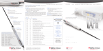
• User manual •
• User manual • SHOULDER
Before use, please read this document.
Kinetec reserves the right to effect technical modifications.
Summary
Page
• Definition__________________________________________________________ 2
• Description ________________________________________________________ 3-4
• Base assembly ______________________________________________________ 5
• Unit transport_______________________________________________________ 5
• Safety ____________________________________________________________ 6
• Electrical connection __________________________________________________ 6
• Use of the hand control
- Select your language ________________________________________________ 7
- Locking the hand control setting ________________________________________ 7
- START/STOP/REVERSE function _________________________________________ 8
- Quick Start_______________________________________________________ 8
- Possible values for each parameter ______________________________________ 8
- How to adjust the basic parameters of the movement? __________________________ 9
- How to modify programs PROGRAM MODE? _________________________________ 10-11
- Using Programs ___________________________________________________ 12
- Reading the values of a program ________________________________________ 12
- How to define the upper and lower movement limits? ___________________________ 13
• Instructions for use
- How to use the pads ________________________________________________ 14
- Assembling the parts ________________________________________________ 15
- Range of motion ___________________________________________________ 16
- Adjustment of the range of motion _______________________________________ 16
- Patient set up on BED _______________________________________________ 17
- Patient set up on WHEELCHAIR _________________________________________ 18
• Product information
- Options _________________________________________________________ 19
- Maintenance______________________________________________________ 19
- Troubleshooting ___________________________________________________ 19
- Cleaning ________________________________________________________ 19
- Technical specifications ______________________________________________ 19
- Symbols used _____________________________________________________ 20
- Warranty ________________________________________________________ 20
- Maintenance sheet _________________________________________________ 21
SAFETY RECOMMENDATIONS
• Before use, please read this document.
• The physician defines the protocol and ensures that it is correctly implemented (adjustments, session time and
frequency of use).
• We recommend that you lock the hand control when you give it to the patient.
• For optimum safety, always give the hand control to the patient before starting the system.
• Explosion hazard: KINETEC Centura B&W is not designed for use in the presence of flammable anesthetics.
• Check that the electrical socket is in good condition and is suitable for the splint power supply cord. The latter
complies with current standards and has a grounding socket. The plug may be connected to any standard socket.
The socket must however have a grounded pin. To connect the power supply, only use the original cable supplied
with the machine. Check that the cables remain free around the device so that they do not get damaged.
Kinetec reserves the right to effect technical modifications.
Manuel N°: 467896283 – Update November 2003
Page 1
EN
Definition
The KINETEC Centura B&W is a SHOULDER CONTINUOUS PASSIVE motion device enabling the following movements:
• Flexion / Extension Arm STRAIGHT from 0° to 110°.
• Flexion / Extension Arm FLEXED from 30° to 110°.
Your machine can be used with all bed and wheelchair available on the market.
Indications
• Total shoulder replacement.
• Repeated dislocation of the humerus.
• Rotator cuff injury.
• Upper humerus fractures
• Scapula fractures.
• Acromioplasty.
• Capsulotomy.
• Arthrolysis.
• Synovectomy for Rheumatoid Arthritis.
• All type of shoulder styffness joint.
Clinical Benefits
• Breaks the cycle of trauma, inflammation and the loss of range of motion.
• Prevents joint stiffness.
• Speeds the recovery of post-operative range of motion.
• Maintains the quality of the joint surface.
• Reduces pain and edema.
• Promotes joint cartilage healing.
• Reduces hospitalization time
• Reduces the need for pain medication.
• Provides immediate post-operative continuous passive motion.
• Digital ROM readout on the patient hand control for positive reinforcement.
• Maintains desired positions for stretching and muscular rest.
Contraindications
• Unstable fractures.
• Spastic paralyses.
• Uncontrolled infection.
• The machine is not adapted for patients height more 2m(6’7”) or under 1.4m(4’7”).
EN
Page 2
Description
The KINETEC Centura B&W consists of the following components
1 – Base
2 – Wheels
3 – Sliding motor mount bar (left/right)
4 – Locking knob of the right/left sliding motor mount bar
5 – Locking knob of the up/down sliding housing
6 – Base locking knob
7 – Locking knob of the motor mount assembly
8 – Motor
9 – Shoulder depth sliding lock
4
7
9
3
5
6
8
1
2
14
10
11
15
13
12
10 – Swiveling splint support lock
11 – Swiveling splint support
12 – Elbow flexion setting lock
13 – Arm splint
14 – Arm splint lock
15 – Forearm length setting lock
Page 3
EN
Description
19
16 – Supply cable connector switch
17 – Fuse
18 – ON/OFF switch
19 – Hand control lock switch
20 – Defect or power light
21 – Motor or hand control connectors
22 – Hand control location for transport
23 – Hand control
20
23
21
17
18
16
22
25 26
24
EN
27
29
30
28
31
36
33
32
34
35
24 – Liquid-crystal display (2 lines of 16 characters)
25 – Arm Straight flexion/extension key
26 – Arm Flexed flexion/extension key
27 – Lower limits setting
28 – Upper limits setting
29 – Increase / decrease keys
30 – START key
31 – STOP key
32 – FORCE key
33 – SPEED key
34 – PAUSE key
35 – TIMER key
36 – PROGRAM access key
Page 4
Base assembly
Remove all the components from their packaging.
• Position the column (37) onto the base (1). To fit the nut (38) of the column into the hole (39) of the base, tighten
the screw (40) with the wrench (41) delivered with the machine.
• Position the housing (42) on the column (37), make sure the joint (43) is positioned on the side of the long bar of
the base (1), lock the knob (6).
• Place the motor (8), see page 15 for the correct position.
37
42
43
37
6
38
1
39
40
41
1
8
Unit transport
44
For easy transport, the unit features 4 wheels with brakes and the
sliding motor mount bar (44) that also functions as a handle.
5
You can adjust the height of the handle with knob (5).
Page 5
EN
Safety
The physician defines the protocol and ensures that it is correctly implemented (adjustments, session duration and
frequency of use).
The patient must know the start/stop/reverse function on the control handle. Hand control must be accessible to patient
at all times. (See page 8).
KINETEC Centura B&W complies with Directive 93/42/CEE.
EXPLOSION HAZARD:
KINETEC Centura B&W is not designed for use in the presence of flammable anaesthetics.
In case of electromagnetic interference with other devices move the device.
KINETEC Centura B&W is in compliance with standards in force (IEC 601.1.2), electromagnetic compatibility standard for
medical devices.
Please, do not touch the moving parts while the unit is running, pinching risk.
Check the well fixation of the knobs (7) and (9) (page 3) before each using.
Electrical connection
KINETEC Centura B&W is a type B class I device.
Before connecting the device to the power supply, check that the mains voltage
matches that shown on the identification plate (100-240 V~ 50-60Hz).
18
Connect the power supply cable (45).
45
IMPORTANT
Check that the electrical socket is in good condition and is suitable for the splint
power supply cord. The latter complies with current standards and has a
grounding socket.
The plug may be connected to any standard socket.
The socket must however have a grounded pin.
To connect the power supply, only use the original cable supplied with the
machine.
Check that the cables remain free around the device so that they do not get
damaged.
The cables (motor and hand control) can be plugged in any of the connectors
Starting the unit
Switch on (3). The light (20) is ON
While the unit begins an auto diagnostic, the display shows the following
KINETEC
CENTURA B&W V1.0
Movement verif.
MOToR : M1
Movement verif.
Please wait
Arm FLEXED
50 STOP
0
90
Your KINETEC Centura B&W is ready to be used.
EN
Page 6
20
Use of the hand control
Select your language
Beginning
Keys to press
Switch the unit ON
Display
Remarks
KINETEC
CENTURA B&W V1.0
Movement verif.
Please wait
Movement verif.
MOToR : M1
Arm FLEXED
50 STOP
0
90
Check if the hand control is not locked
(See page 7).
Language
ENGLISH
Press the 2 keys in the same time
The display indicates the language
selected.
The English language is selected.
To change the language
Language
FRENCH
or
Arm FLEXED
50 STOP
0
90
To validate the new language.
English
French
German
Italian
Spanish
To exit and confirm the new language,
switch OFF and Switch ON the unit.
Locking the hand control setting
The hand control allows the patient to control the machine as appropriate.
The switch (19) has 3 positions:
19
LOCKED POSITION
The operational settings can be read and the START/STOP/REVERSE function
operated.
UNLOCKED POSITION
All adjustments are possible.
HALF-LOCKED POSITION
It is possible to switch the program and modify the upper and
lower movement limits. The START/STOP/REVERSE function is
always accessible.
Double locking
Simultaneously press the
and
keys to lock the hand control.
The display reads LOCK. To unlock the hand control, simultaneously press the same keys.
The displays reads UNLOCK.
You can not change the parameters, if you try the display reads: LOCK
We recommend that you lock the hand control
when you give it to the patient.
Comment: The hand control is unlocked when you switch the unit ON/OFF.
Page 7
EN
Use of the hand control
START/STOP/REVERSE function
As with all KINETEC systems, KINETEC Centura B&W is equipped with a START/STOP/REVERSE function.
When the unit is running, the display reads RUN
Press the
key of the hand control. The movement stops. The display reads STOP.
Press the
key of the hand control. The movement starts in the opposite direction and the display reads RUN.
Caution:
For optimum safety, always give the hand control to the patient before starting the system.
Quick Start
Set up the patient and proceed as below:
Beginning
Keys to press
Display
Remarks
KINETEC
Centura B&W V01.0
Movement verif.
Please wait
Arm straight
30 STOP
0 90
Switch the unit ON
50
ARM FLEXED
STOP
0 90
30
Arm straight
STOP
0 90
To choose the movement
Start the session with the original parameters of the
movement (default setting).
Check if the hand control is not locked
(See page 7).
The display shows the new movement selected
and the default settings of the upper and lower
limits of this movement.
The value change at the speed of the
movement.
Arm straight
30 STOP
0 90
Default setting values for each parameter:
Arm Straight Flexion/Extension
Arm Flexed Flexion/Extension
30°
90°
50°
90°
• Speed
2
2
• Force
6
6
• Extension Pause
0
0
• Flexion Pause
0
0
No timer
No timer
Arm Straight Flexion/Extension
Arm Flexed Flexion/Extension
• Lower limit
0° to 105°
30° to 105°
• Upper limit
5° to 110°
35° to 110°
• Lower limit
• Upper limit
• Timer
Possible values for each parameter:
• Speed
1 to 5 (from 45° to 130° per minute)
• Force
1 to 6
• Extension Pause
0 to 900 seconds (15minutes)
• Flexion Pause
0 to 900 seconds (15minutes)
• Timer
EN
No timer (00H00) to 24H00
Page 8
Use of the hand control
How to adjust the basic parameters of the movement?
Beginning
Keys to press
Display
To stop the unit
30
Arm straight
STOP
0 90
50
Arm FLEXED
STOP
0 90
30
Arm straight
STOP
0 90
To choose the movement
To display the extension or flexion limit of the movement
To change the limit if necessary
Arm straight
30 Ext
0 90
or
or
Arm straight
20 FLEX
0 90
20
Arm straight
FLEX
0 110
Arm straight
SPEED 2
To validate the new value, press another key
or wait more than 3 seconds.
LOAD _ _ _ _ _ _
No timer
Arm straight
PAUSE HIGH
0
Pause low
0
Or
Or to display pause in extension or flexion limit
To change the pause if necessary
To validate the new value press another key
or wait more than 3 seconds. The display shows the
selected mode.
Arm straight
PAUSE low
15
or
20
Arm straight
STOP
0
110
Remarks
Check if the hand control is not locked
(See page 7).
The display shows the new movement selected
and the default settings of the upper and lower
limits of this movement.
The value blinks.
The new value blinks.
While the value blinks press
the
or
key
to change if necessary.
Successive presses on this key selects the
pause at the extension or flexion limit.
The new pause value blinks.
The unit is ready to start with the new
parameters.
Comments:
• The values shown in the ‘Display’ column are examples.
Page 9
EN
Use of the hand control
How to modify programs PROGRAM MODE ?
Beginning
Keys to press
Display
Remarks
To switch off the unit
KINETEC
Centura B&W V01.0
Press the two keys at the same time and switch the unit
ON
Then
To change the program if necessary
or
Program
EMPTY
2
Program
EMPTY
10
Welcome text during 3 seconds.
The program number blinks.
The new program number blinks.
Arm FLEXED
50 prg nr10 90
To choose the movement
Arm STRAIGHT
30 prg nr10 90
0
To display the extension or flexion limit of the movement
To change the limit of movement if necessary
To validate the new value, press another key
or wait more than 3 seconds
or
or
Arm STRAIGHT
prg nr10
90
Arm STRAIGHT
0 prg nr10
90
0
The display shows the new movement selected.
Arm STRAIGHT
prg nr10
110
The new value blinks.
While the value blinks press
Arm STRAIGHT
SPEEd:
2
the
Load : _ _ _ _ _ _
No timer
Pause low
The value blinks.
or
key
to change if necessary.
0
To record the program 10
Arm STRAIGHT
Save:+
clear:-
Then
Arm STRAIGHT
Saving
Program
11
EMPTY
The program 10 has been recorded and the
display indicates the next program so you can
change another program.
Arm STRAIGHT
clearng
Program
11
EMPTY
The program 10 has been cancelled and the
display indicates the next program so you can
change another program.
OR
To cancel the program
To exit program mode, switch OFF and switch ON the unit.
EN
KINETEC
Centura b&W V01.0
Page 10
To use the modified program see page 12.
Page 11
16
15
14
13
Lower limit
Upper Limit
Speed
Force
Pause on upper limit
Pause on lower limit
Timer
Program
EMPTY
12
11
10
Movement type
Comments:
• When a program has been deleted, the display shows
9
8
7
6
5
4
3
2
1
• N Program
number
Use of the hand control
11
Program table:
EN
Use of the hand control
Using Programs
The KINETEC Centura B&W allows you to store up to 16 programs, including the type of movement, ROM, speed, load,
pauses and timer.
The original parameter values of the program are empty.
These values can be modified and recorded at any time (see ‘How to enter a program’ page 10).
Beginning
Keys to press
Display
Arm FLEXED
STOP
0
110
50
To Stop the Unit
To access the program mode
or
To change the program if necessary
To exit and validate the selected program
The program number blinks.
ARM STRAIGHT
0 prg nr 10
110
The new program number blinks.
ARM STRAIGHT
STOP
0 110
Arm FLEXED
STOP
0
110
50
Start the unit
Check if the hand control is not locked
(See page 7).
ARM STRAIGHT
15 prg nr 8
90
0
To exit without validation of selected program
Remarks
0
ARM STRAIGHT
STOP
0 110
The current parameters have been recorded in
program 3.
Back to the starting parameters.
The value change at the speed of the
movement.
Reading the values of a program: example SPEED
Beginning
Keys to press
5
To Stop the Unit
To read the speed value
After 5 seconds or after pressing on another key
ARM STRAIGHT
STOP
0 80
ARM STRAIGHT
15 prg
nr 8
90
To access the program mode
To change the program if necessary
Display
or
ARM STRAIGHT
0 prg nr 10
110
ARM STRAIGHT
SPEED :
5
5
Remarks
Check if the hand control is not locked
(See page 7).
The program number blinks.
To change the program if necessary.
Displays the speed value.
ARM STRAIGHT
STOP
0 80
To exit and validate the selected program
ARM STRAIGHT
0 Stop
0 110
The current parameters have been recorded in
Start the unit
ARM STRAIGHT
0 Stop
20 110
The value change at the speed of the
program 3.
movement.
Comments:
• The values shown in the ‘Display’ column are examples. They actually depend on the stored programs.
• The current movement parameters can be changed while using that program but no data will be stored in
the original program. See the programming mode (p 10) to modify programs
EN
Page 12
Use of the hand control
How to define the upper and lower movement limits?
• At the start of a session
The MANUAL MODE is a way to set within the tolerance of a patient at the beginning of a session.
Set up the patient and proceed as below:
Beginning
Keys to press
Display
Remarks
KINETEC
Centura B&W V01.0
Movement verif
Please wait
ARM STRAIGHT
0 Stop
20 110
Check if the hand control is not locked
(See page 7).
ARM STRAIGHT
0 Manual 65
110
The unit is moving to the upper limit of the
ARM STRAIGHT
0 Manual 15
65
The new upper value limit of the movement is
To select the manual mode for lower limits
ARM STRAIGHT
0 Manual 15
65
The unit is moving to the lower limit of the
movement
To set the pain level when reached, immediately press
ARM STRAIGHT
15 Manual 15
65
The new lower value limit of the movement is
recorded.
To start the session with the new movement limits
15
Switch the unit ON
continuous press
To select the MANUAL MODE for upper limits by
continually holding pressure on the key
To set the pain level when reached, immediately press
continuous press
ARM STRAIGHT
Run
15
65
movement.
recorded.
The angle display changes with current
movement.
• During the session
This function, The BY-PASS MODE is a way to address the pain threshold of a patient during a session.
IMPORTANT: Can be used only when the machine RUN.
Beginning
Keys to press
The unit is running
Display
15
continuous press
ARM STRAIGHT
Run
15
65
Remarks
Check if the hand control is not locked
(See page 7).
To select the BY-PASS MODE
ARM STRAIGHT
15 bypass
80 65
The unit exceeds the recorded upper limit.
To set the new pain level when reached, immediately
press
ARM STRAIGHT
15 bypass
80 80
The new upper value limit of the movement is
recorded.
continuous press
To select the BY-PASS mode for lower limits
ARM STRAIGHT
15 bypass
5 80
The unit is moving to the lower limit of the
movement.
ARM STRAIGHT
5 bypass
5 80
The new lower value limit of the movement is
press
Continue the session with the new movement limits.
ARM STRAIGHT
5 RUN
5
80
The angle display changes with current
To set the new pain level when reached, immediately
recorded.
movement.
Comments:
• The values shown in the ‘Display’ column are examples.
Page 13
EN
Instructions for use
How to use the pads
KINETEC Centura B&W is delivered with 3 straps:
• 1 arm strap (A)
A
• 2 forearm arm strap (B).
B
All these straps are used the same way (see pictures).
Do not tighten the straps too much.
For best results, clean or replace the straps after each patient.
EN
Page 14
Instructions for use
Assembling the parts
For a left shoulder
For a right shoulder
7
7
46
46
• Position the shoulder depth bar (46).
• Tighten the knob (7).
9
9
8
8
• Position the motor (8).
• Tighten the knob (9).
• Plug the motor.
47
47
• Use the color code to position the splint (47):
- Blue for left arm.
- Red for right arm.
The assembly is secured when you hear a (click).
13
13
• Position the arm splint (13).
The assembly is secured when you hear a (click).
Page 15
EN
Instructions for use
Range of motion
• Kinetec Centura B&W provides motion from 0° to 110° of flexion
when the arm straight movement is selected.
• Kinetec Centura B&W provides motion from 30° to 110° of flexion
when the arm flexed movement is selected.
Adjustment of the range of motion
To position the motor mount bar (46) determine the range of motion of the movement and the position of the 0° machine.
Position A: range of motion for use with a wheelchair.
Position B: range of motion for use with a bed.
All positions are possible, that allows working more precisely the patient range of motion.
Position A
Position B
110°
0°
46
110°
110°
46
0°
110°
0°
EN
Page 16
Instructions for use
Patient set up on BED
Make sure the straps are clean.
Put the unit in the position that is the most comfortable for the patient.
b
a
46
17
4
47
• Position the patient in the bed in a comfortable position and supporting the affected arm.
• Position the Kinetec Centura B&W as close as possible of the bed and lock the wheel brakes.
• Unscrew the knob (17) and adjust the position of the splint (47), make sure the motor mount bar (46) is parallel with the
patient’s upper body.
• For other positions see page 16.
• Slide the splint (47) toward the patient, use the knob (4) and put the arm in the supports, secure pads.
• Adjust the lengths
a – arm.
b – forearm.
Starting the unit
• Choice of the motion:
- Press
or
- or select a program
and adjust your parameters (see page 9).
(see page 12).
Page 17
EN
Instructions for use
Patient set up on WHEELCHAIR
Make sure the straps are clean.
Put the unit in the position that is the most comfortable for the patient.
7
b
a
4
46
47
• Position the patient in the wheelchair in a comfortable position and supporting the affected arm.
• Position the Kinetec Centura B&W as close as possible of the wheelchair and lock the wheel brakes.
• Unscrew the knob (17) and adjust the position of the splint (47), make sure the motor mount bar (46) is parallel with the
patient’s upper body.
• For other positions see page 16.
• Slide the splint (47) toward the patient, use the knob (4) and put the arm in the supports, secure pads.
• Adjust the lengths
a – arm.
b – forearm.
Starting the unit
• Choice of the motion:
- Press
or
- or select a program
EN
and adjust your parameters (see page 9).
(see page 12).
Page 18
Product information
OPTIONS
Recharger
Transport bag
Maintenance
After 2,000 hours of operation, KINETEC Centura B&W requires a few lubrication and maintenance operations (lubrication of the joints and pointer
stops).
The need for maintenance is indicated by display of the message SERV. MOTOR when the system is switched on.
Despite that warning, you can continue to use your KINETEC Centura B&W by pressing START, but you should contact your nearest KINETEC
technician to have the maintenance operations conducted as soon as possible.
• A motor running time counter is available. Simultaneously press keys
RESET TIME 924H
Reset: limit low
and
this counter can be resetting by pressing the key
, the displays shows
.
Troubleshooting
A spare parts list and technical catalog are available to you on request from your KINETEC distributor.
If, after connecting the power supply cable to the power supply and switching on KINETEC Centura B&W:
• The display does not indicate any information:
- Check that the electrical socket is live using another device.
- Replace the fuse(s) (17) of the connector with fuses of the same type and caliber:
2 fuses T 750 mA 250V (6.3 x 32) (KINETEC order: 4610007434).
17
- If the display still does not indicate any information, contact your nearest KINETEC technician.
• Your KINETEC Centura B&W does not work and the display indicates 50 STOP 25 110,
Press START again.
Your KINETEC Centura B&W still does not function: Contact your nearest KINETEC technician.
• Your KINETEC Centura B&W does not function and the display indicates:
ANGULAR POSI.: angle measurement function failure,
or NO MOVEMENT: no movement,
or BAD WAY: motor rotation failure,
or LOAD MAXI: abnormal consumption,
or POWER SUPPLY: power failure;
Contact your nearest KINETEC technician if the same message is displayed after having switched the device off, then on, and started it by
pressing START.
Cleaning
Before conducting any cleaning operation, SWITCH the unit OFF and disconnect the power supply.
Use a DISINFECTANT (PROPANOL/ISOPROPANOL or ALDEHYDE-based solution). Spray the disinfectant on the SURFACES (plastic shells and metal components).
In order to ensure optimal hygiene, you are advised to clean the covers for each new patient. All the consumables enable hazard-free disposal.
Recommendations to obtain a maximum hygiene of the pads:
• Sterilization of the pads (if necessary) : Sterilizer at 134 °C during 18 minutes.
• Disinfection of the pads:
Washing at 30°C with use of a disinfection solution during the rising cycle.
Example of product which can be used:
Solution "Baclinge" at 0.125 % or "Souplanios" at 0,125% from ANIOS Laboratory.
A complete list of distributors in your country is available on request.
Page 19
EN
Product information
Technical specifications
Environment
- Storage/transport conditions:
Temperature: -40 to 160°F / -40 to 70°C
Relative humidity: up to 90%
- Operating conditions:
Room temperature: 50 to 105°F / 10 to 40°C
Relative humidity: up to 80%+40°C.
Electrical:
Power supply: 100-240 V~
Frequency: 50-60 Hz
Power consumption: 50 VA
Device of type B class I
IP 20.
Fuse T 750mA 250V 6.3x32mm
(KINETEC order: 4610007434)
Product:
Weight: 48 lbs (22 Kg)
Unit dimensions:
22 x 39 x 30 inches
56 x 100 x 76 cm
Angular limits: see page 2
Speed: from 45 to 130°/min
Patient sizing:
from 4’7” to 6’7”
1,40 to 2m
Symbols used
TYPE B device
(protection against electric shocks)
Lower limit
Caution
(consult the accompanying documents)
Upper limit
STOP (power off)
Arm straight flexion/extension movement
ON (power on)
Arm flexed flexion/extension movement
Start movement
Hand control locked
Stop movement
Hand control unlocked
Program access
Hand control half locked
Speed
Switch on LED and defect signal when the LED
blinks
~
Timer
Alternative current
Force
Pause
Increase
Decrease
Warranty
The KINETEC warranty is strictly limited to the replacement free of charge or repair in the plant of the component or components found to be defective.
KINETEC guarantees its continuous passive motion systems for 1 year against all defects of manufacture from the date of purchase by the consumer.
KINETEC is the only organization able to assess the application of the warranty to its systems.
The warranty will be considered null and void if the device has been used abnormally or under conditions of use other than those indicated in the user's
manual.
The warranty will also be considered null and void in the event of deterioration or an accident due to negligence, inappropriate surveillance or inappropriate
maintenance, or due to transformation of the equipment or an attempt to repair the equipment.
EN
Page 20
Product information
Maintenance sheet
Serial number: _______________
Purchase date: ____________________
Date: ________________________________________________
Operations done: _____________________________
Technician: ____________________________________________
_________________________________________
Running time (see page 19): _________________________________
_________________________________________
Exchange parts: _________________________________________
_________________________________________
____________________________________________________
_________________________________________
Page 21
EN