1
CALIFORNIA STATE UNIVERSITY, NORTHRIDGE
FPGA Based Navigation and Control for Small Aircraft
A graduate project submitted in partial fulfillment of the requirements
For the degree of Master of Science in Electrical Engineering
By
Benjamin Posler Criel
May 2014
Signature Page
The graduate project of Benjamin Posler Criel is approved:
___________________________________________
Dr. Kourosh Sedghisigarchi
______________
Date
___________________________________________
Dr. Sharlene Katz
______________
Date
___________________________________________
Dr. George Law, Chair
______________
Date
CALIFORNIA STATE UNIVERSITY, NORTHRIDGE
ii
Table of Contents
Signature Page ......................................................................................................................................... ii
List of Figures .........................................................................................................................................iv
List of Tables ..........................................................................................................................................iv
Abstract ....................................................................................................................................................v
I.
INTRODUCTION ..................................................................................................................................1
1) SYSTEM ARCHITECTURE ....................................................................................................................2
II.
RADIO/RECEIVER ...............................................................................................................................4
1)
2)
3)
4)
5)
III.
SERVOS ..............................................................................................................................................4
FMA DIRECT CO-PILOT SYSTEM .......................................................................................................6
GPS RECEIVER ..................................................................................................................................7
DE0-NANO FPGA EVALUATION BOARD ...........................................................................................8
SIGNAL PATH .....................................................................................................................................8
PROTOCOLS....................................................................................................................................... 10
1) UBLOX UBX MESSAGES .................................................................................................................. 10
2) GPS UART COMMUNICATION ........................................................................................................ 11
3) PWM SIGNALS ................................................................................................................................ 12
IV. SOFTWARE ........................................................................................................................................ 13
1)
2)
3)
4)
V.
PWM GENERATORS......................................................................................................................... 17
PWM MEASUREMENT ..................................................................................................................... 17
CONTROL LOGIC .............................................................................................................................. 18
DATA ACQUISITION AND STORAGE .................................................................................................. 20
RESULTS............................................................................................................................................. 21
1) FLIGHT #8 ........................................................................................................................................ 21
2) FLIGHT #9 ........................................................................................................................................ 25
3) FLIGHT #10 ...................................................................................................................................... 27
VI. CONCLUSIONS .................................................................................................................................. 29
1) LIMITATIONS ................................................................................................................................... 29
2) ISSUES.............................................................................................................................................. 30
3) IMPROVEMENTS ............................................................................................................................... 30
REFERENCES .............................................................................................................................................. 31
APPENDICES ............................................................................................................................................... 32
Appendix A: GPS Message Definitions ................................................................................................. 32
Appendix B: Qsys Setup ........................................................................................................................ 34
Appendix C: PWM Generator VHDL Code .......................................................................................... 40
Appendix D: PWM Measurement VHDL Code .................................................................................... 43
Appendix E: Navigation C Code ............................................................................................................ 45
Appendix F: C Code Header File ........................................................................................................... 58
Appendix G: Early Flight Data .............................................................................................................. 59
iii
List of Figures
Figure 1.1: Slowpoke by Great Planes ................................................................................ 1
Figure 1.2: Altera DE0-nano FPGA Evaluation Board ...................................................... 2
Figure 2.1: 6EXP 6-channel PCM/PPM (FM) .................................................................... 4
Figure 2.2: S3003 Servo ..................................................................................................... 5
Figure 2.3: 4-Channel R/C aircraft controls ....................................................................... 6
Figure 2.4: FMA Direct Co-Pilot System ........................................................................... 7
Figure 2.5: UBlox Neo-6m GPS Receiver (w/ Antenna) ................................................... 7
Figure 2.6: Altera DE0-nano Evaluation Board (top view) [2] .......................................... 8
Figure 2.7: Signal Path Diagram ......................................................................................... 9
Figure 3.1: UBX Packet Structure [3]............................................................................... 10
Figure 3.2: GPS Wiring .................................................................................................... 11
Figure 3.3: PWM waveforms ............................................................................................ 12
Figure 4.1: Software Flow Chart ...................................................................................... 14
Figure 4.2: QSYS Design ................................................................................................. 15
Figure 4.3: ARCTAN Approximation .............................................................................. 16
Figure 4.4: Proportional Pitch Control.............................................................................. 19
Figure 4.5: Proportional Yaw Control .............................................................................. 19
Figure 5.1: Flight #8 Latitude/Longitude Plot .................................................................. 22
Figure 5.2: Flight #8 Map Plot .......................................................................................... 23
Figure 5.3: Flight #8 Heading and Altitude data .............................................................. 24
Figure 5.4: Flight #9 Latitude/Longitude Plot .................................................................. 25
Figure 5.5: Flight #9 Heading and Altitude data .............................................................. 26
Figure 5.6: Flight #10 Latitude/Longitude Plot ................................................................ 27
Figure 5.7: Flight #10 Heading and Altitude data ............................................................ 28
Figure G.1: Flight #5 Latitude/Longitude Data ................................................................ 60
Figure G.2: Flight #5 Heading and Altitude data ............................................................. 61
Figure G.3: Flight #6 Longitude/Latitude Data ................................................................ 62
Figure G.4: Flight #6 Heading and Altitude data ............................................................. 63
Figure G.5: Flight #7 Longitude/Latitude Data ................................................................ 64
Figure G.6: Flight #7 Heading and Altitude data ............................................................. 65
List of Tables
Table 3.1: Message Headers ............................................................................................. 11
iv
Abstract
FPGA Based Navigation and Control for Small Aircraft
By
Benjamin Posler Criel
Master of Science in Electrical Engineering
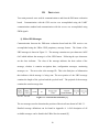
The purpose of this project was to create a small Un-manned Aerial Vehicle (UAV)
capable of flying pre-programmed routes controlled by a Field Programmable Gate Array
(FPGA) board. A GPS receiver was used to determine the aircraft’s longitude, latitude,
heading and altitude. The navigation of the aircraft was a waypoint system in which the
aircraft flew to a designated waypoint before traveling to the next waypoint. Movement
of the control surfaces of the plane was accomplished using Futaba servos. These were
controlled by sending a pulse width modulated (PWM) signal to each servo. The time
duration of each pulse corresponded to a position of the servo. Pitch and roll stability
were maintained using the Co-Pilot from FMA Direct. This device used infrared sensors
to detect the horizon in four directions forward, aft, left and right of the aircraft. The
device used these measurements to make changes to the control surfaces to maintain level
flight. This device greatly simplified turning the aircraft because only one degree of
freedom was needed to turn the aircraft (yaw). Take-offs and landings were locally
controlled by an operator on the ground. The on/off of the FPGA was controlled using an
additional channel of the receiver.
v
I.
INTRODUCTION
Unmanned Aerial Vehicles (UAVs) have become common place in the world today.
These aircraft are capable of carrying a multitude of instruments into areas too dangerous
to send a human pilot such as high altitude flights and behind enemy lines.
The
capability of these aircraft and the always improving reliability of the navigation systems
and communication between aircraft and ground system have made UAVs a fast growing
industry. The purpose of this project was to create a small UAV capable of flying preprogrammed routes. The UAV used for this project was the “Slowpoke” radio controlled
plane designed by Great Planes as shown in Figure 1.1.
Field Programmable Gate Arrays (FPGAs) are also a fast growing industry as chips
increase in speed and grow in the number of available logic units, FPGAs are taking
ahold of a larger market share where small chip size and fast processing are requirements.
FPGAs are great for data requirements that have large throughput. For this reason,
FPGAs are even making their way into the UAV industry for the processing of synthetic
aperture radar images. Figure 1.2 shows an Altera DE0-nano FPGA evaluation board
which was used for the navigation system.
Figure 1.1: Slowpoke by Great Planes
1
Figure 1.2: Altera DE0-nano FPGA Evaluation Board
1) System Architecture
The UAV navigation system consisted of five main components: The radio/receiver,
servo motors, FMA Direct Co-Pilot, Global Positioning System (GPS) receiver, and the
DE0-nano board. For this project the radio/receiver was used for take-offs and landings
in which a pilot on the ground controlled the aircraft during these two phases of flight.
The servo motors, or servos, are used to move the control surfaces of the aircraft and can
be controlled by either the radio/receiver or the DE0-nano. The FMA Direct Co-Pilot
system was added for additional stability and simplification of the navigation algorithms.
The Co-Pilot system consists of four infrared sensors and a control module. The infrared
sensors account for variations in pitch and roll of the aircraft and can assist in
maintaining level flight.
A GPS receiver is only form of location fixing for the
navigation system of this project. The GPS receiver consists of a 1”x1” antenna and the
UBlox Neo-6m GPS receiver chip.
The DE0-nano evaluation board consists of a
Cyclone IV FPGA chip with a Nios II processor for calculating the navigation of the
2
plane and control signals for the servos. In addition, on-board memory is also available
for storing aircraft position, aircraft heading and waypoint information.
3
II.
RADIO/RECEIVER
The radio/receiver allow for ease of the more complicated phases of flight: take-off and
landing. The radio used for this project was the Futaba 6EXP 6-channel PCM/PPM (FM)
selectable Radio control system. The “Slowpoke” requires only a 4-channel radio to
move all of the control surfaces. The extra two channels were necessary as an on/off
switch for the DE0-nano and the Co-Pilot system. This particular radio operates at 72
MHz and channel 52. Figure 2.1 contains an image of the 6EXP radio.
Figure 2.1: 6EXP 6-channel PCM/PPM (FM)
Selectable Radio control system
1) Servos
The servo motors used for this project were Futaba S3003 servo motors. Five were
required for this aircraft. Specifications for the servos are shown in Figure 2.2
4
Figure 2.2: S3003 Servo
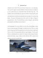
A simple conventional plane (fuselage, wing, horizontal and vertical stabilizers) is
comprised of four different methods for controlling aircraft movement: Ailerons to
control roll angle, elevator to control pitch angle, rudder to control yaw angle, and
throttle to control the aircraft speed. The servo motors for these controls are located
within the fuselage with the exception of the aileron servo motors which are located on
the wings. The control surfaces, throttle servo locations are shown in Figure 2.3
.
5
Figure 2.3: 4-Channel R/C aircraft controls
Servo motor locations
(Bottom View)
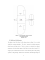
2) FMA Direct Co-Pilot System
The addition of the FMA Direct Co-Pilot System, shown in Figure 2.4 was to help
simplify the navigation algorithms.
This device “measures the infrared temperature
(heat) between the Earth and sky. The sky is always at a relatively lower infrared
temperature, while the infrared signature of the Earth is always relatively warmer” [1].
Using two pairs of infrared sensors the device can sense when the plane is either pitching
up/down, or rolling left/right. Based on these measurements, the PWM signal being sent
6
to the servos is altered to maintain level flight.
With the help of this device, the
navigation is simplified to only changes in heading (yaw).
Figure 2.4: FMA Direct Co-Pilot System
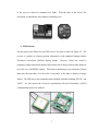
3) GPS Receiver
For this project, the UBlox Neo-6m GPS receiver was used as shown in Figure 2.5. The
receiver is capable of relaying position information in the standard National Marine
Electronics Association (NMEA) display format.
However, Ublox has created a
proprietary output format that displays the position data in integer format rather than text
(as is the case with NMEA format). This makes transitioning to processing the position
data easier because there is no need for a text parser, as the data is already in integer
format. The GPS has several communication standards available including SPI, I2C, and
UART.
For this project the Universal Asynchronous Receiver/Transmitter (UART)
communication ports were utilized.
Figure 2.5: UBlox Neo-6m GPS Receiver (w/ Antenna)
7
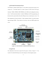
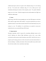
4) DE0-nano FPGA Evaluation Board
The DE0-nano evaluation board (Figure 2.6) was chosen for this project because of its
compact size. The board features an “Altera Cyclone IV FPGA (with 22,320 logic
elements), 32MB of SDRAM, 2Kb EEPROM, and a 64Mb serial configuration memory
device.” [2] The board also includes “a built-in USB Blaster for FPGA programming, and
the board can be powered either from this USB port or by an external power source.” [2]
Most importantly, the board includes 2 40-pin expansion headers for general purpose
input and output (GPIO). These headers are necessary to drive the PWM signals to the
servos.
Figure 2.6: Altera DE0-nano Evaluation Board (top view) [2]
5) Signal Path
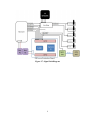
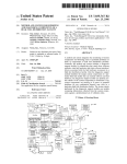
The culmination of the devices required for this project is shown in Figure 2.7. The
Cyclone IV with the NIOS II processor is the centerpiece of the navigation system.
8
Figure 2.7: Signal Path Diagram
9
III.
PROTOCOLS
Two main protocols were used for communication to and from the DE0-nano evaluation
board.
Communication with the GPS receiver was accomplished using the UART
communication standard and communication with the servos was accomplished using
PWM signals.
1) Ublox UBX Messages
Communication between the DE0-nano evaluation board and the GPS receiver was
accomplished using the UBlox UBX proprietary message format. The format of the
UBX messages is shown in Figure 3.1. The message contains two sync characters: 0xB5
0x62 which indicate the message is of the UBX format. Following the sync characters
are the class indicator.
The class of the message indicates the basic subset of the
message, whether it contains navigation data, configuration messages, monitoring
messages, etc. The next value is the message ID. This is the final piece of information
that indicates which message is being sent. The next portion of the UBX message
contains the length of the payload and the payload itself. The payload of the message
contains the actual message data.
Figure 3.1: UBX Packet Structure [3]
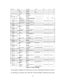
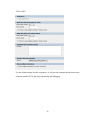
The two messages used to determine the position of the aircraft are shown in Table 3.1.
Detailed message definitions can be found in Appendix A. A full description of all
available messages can be found in the UBlox Neo-6m manual [3]
10
Message Name
NAV-POSLLH
NAV-VELNED
Sync Char 1
Sync Char 2
Class
0xB5
0x62
0x01
0xB5
0x62
0x01
Table 3.1: Message Headers
ID
0x02
0x12
NAV-POSLLH contains the position data including: latitude, longitude, and altitude.
NAV-VELNED contains the speed information of the aircraft including: heading.
2) GPS UART Communication
Transmission of the GPS data was completed using the UART RS-232 standard. Four
wires are connected to the GPS: 3.3 volt line, data transmit, data receive and ground as
shown in Figure 3.2. The data receive line is only required for configuring the GPS and
can be left unconnected if configuration is not required.
Figure 3.2: GPS Wiring
For simplicity, Altera has pre-built UART communication components that can be added
to the QSYS project. The component provides registers for transmit data, receive data,
and status registers. The status register must be continuously monitored for the ready bits
(read and write). When the GPS writes to the port, the data is written to the receive data
register and a read ready bit is set in the status register. By reading the receive data
register, the read ready bit is automatically cleared. The process will send an 8-bit value
11
each time (i.e. 0xB5 or 0x01).
Additional information regarding the Altera UART
component can be found in the Altera Embedded Peripherals IP Users Guide [4]
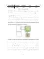
3) PWM Signals
The actuation of the servos is controlled by a pulse width modulated (PWM) signal. The
signal for these servos had a period of 20ms. To actuate the servo left or right the width
of the PWM signal was varied. Roughly 180 degrees of rotation is possible by varying
the pulse width from 1ms to 2ms. Figure 3.3 contains the PWM waveforms for
controlling the servo motors.
Figure 3.3: PWM waveforms
Building these signals was accomplished using a clock counter. For example, the clock
speed on the DE0-nano was 50Hz, meaning each rising edge of the clock occurs every
20ns. To create a PWM signal with period of 20ms and high value of 1ms. The output
will be set to high while the counter counts to 1ms/20ns = 50,000 clock cycles. When the
clock count reaches 50,000 the output is set to low. Then, when the clock count reaches
20ms/20ns = 1,000,000 the output is set high, the clock count is reset, and the process
starts again.
12
IV.
SOFTWARE
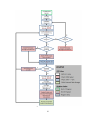
The majority of the software resides as C code written for the NIOS II processor. The
PWM signal generator and code to read a PWM signal are written in hardware language
(VHDL) for the FPGA portion of the Cyclone IV. Figure 4.1 contains a flow chart for the
navigation software. The compilation of components was created using Altera’s QSYS
program. Figure 4.2 contains the QSYS component design for this system. Additional
information regarding the setup for each component is located Appendix B.
13
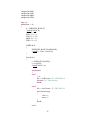
Figure 4.1: Software Flow Chart
14
Figure 4.2: QSYS Design
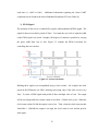
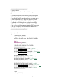
The navigation technique used in this project involved calculating the difference between
true heading (as reported by the GPS) and a desired heading (calculated using current
15
lat/lon and waypoint lat/lon), and using the rudder of the aircraft to drive the heading
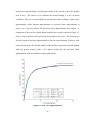
error to zero. The easiest way to calculate the desired heading is to use an arctan
calculation. There are several methods to calculate the arctan, including: Taylor Series
approximation, cordic function approximation, or piecewise linear approximation to
name a few. For this project, the piecewise linear approximation was utilized. A
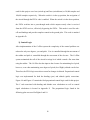
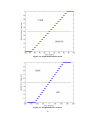
comparison of the piecewise linear function and the true arctan is shown in Figure 4.3.
Only a visual inspection of the piecewise linear function was used. This function can
likely be improved for better approximation of the true arctan function. However, with
errors inherent in the GPS and the inability of the aircraft to truly track a desired heading
with any greater accuracy than a few degrees meant that the piecewise linear
approximation of the arctan did not require optimization.
Figure 4.3: ARCTAN Approximation
16
1) PWM Generators
The software to build the PWM signals for the servo motors was written in VHDL for the
FPGA portion of the Cyclone IV. Three user editable registers exist: Enable, Clock
Divide, and Duty Cycle. If the enable register is set to ‘0’, the PWM counter will be
bypassed, and the input PWM signal sent from the receiver will be copied and sent out.
However, if the enable register is set to ‘1’ a counter will count up at each clock cycle.
The initial PWM output will be a ‘1’, and only after the counter reaches the value stored
in the duty cycle register will the PWM output be set to ‘0’. The counter will reset when
the counter reaches the value stored in the clock divide register. This code is attached in
Appendix C.
2) PWM Measurement
In order to turn on and off the navigation control signals of the FPGA board to the servo
motors an extra channel of the radio/receiver was used. This channel (ch.6) outputs a
PWM signal just like all the other channels. Therefore, VHDL code was written to
sample the PWM signal to measure the duty cycle from this channel. One user editable
register exists: period. This register contains the value that when reached, will cause the
sample counter to reset. For this project the period of the receiver PWM signal was
measured to be 18.5ms (925,000 samples @ 50MHz). This code has only one user
readable register which outputs the duty cycle of the PWM signal. Separate from the
sample counter, there exists another counter to count the number of samples that are read
as a value of ‘1’. Each time the sample counter is reset, the value of this counter is
written to the user readable register. Each time channel 6 on the 6EXP radio switch is
flipped, the duty cycle of this signal changes. The values measured on the 6EXP radio
17
used for this project were 1ms (switch up) and 2ms (switch down) or 50,000 samples and
100,000 samples respectively. When the switch is in the up position, the navigation of
the aircraft through the FPGA code is enabled. When the switch is in the down position,
the FPGA switches into a pass-through mode which outputs exactly what is received
from the 6EXP receiver, effectively bypassing the FPGA. This mode is used for takeoffs and landings and provide complete control to the ground pilot. This code is attached
in Appendix D.
3) Control Logic
After implementation of the Co-Pilot system the complexity of the control problem was
reduced to only two degrees: yaw and pitch. Yaw is controlled through the movement of
the rudder and pitch is controlled through the movement of the elevator. The Co-Pilot
system maintained the roll of the aircraft at wings level which created a flat turn when
using the rudder. The Co-Pilot also has input to the elevator for maintaining level pitch,
however, even when maintaining zero degrees of pitch (level flight), altitude can be lost.
Therefore, the FPGA logic must also account for changes in altitude. Proportional control
logic was implemented for both the heading (yaw) and altitude (pitch) corrections.
Figure 4.4 and Figure 4.5 contain the final proportional control logic used for this project.
The C code associated with heading and altitude error calculations as well as control
signal calculations is located in Appendix E.
following plots was used for flights 9 and 10.
18
The proportional logic found in the
Figure 4.4: Proportional Pitch Control
Figure 4.5: Proportional Yaw Control
19
4) Data Acquisition and Storage
Data was acquired and stored after each GPS update into the Flash memory on the DE0nano board. Interfacing with the flash memory was accomplished using the built-in flash
controller available in the QSYS library.
Data parameters stored in flash memory
included: time, longitude, latitude, altitude, heading, next waypoint longitude, next
waypoint latitude, next waypoint altitude, desired heading, PWM elevator setting, PWM
rudder setting, PWM throttle setting, and navigation enable bit. This data was used to
analyze the accuracy of navigation after each flight.
The configuration file for
programming the on-chip memory is also stored on the flash memory. It is important to
store the data after the configuration data and not to overwrite it.
The Serial
Configuration Devices Datasheet [5] describes the starting address location for each page
of flash memory. Using this datasheet an address of 0x140000 was used to ensure the
configuration information was not overwritten.
20
V.
RESULTS
This project resulted in a successful demonstration of GPS guided navigation using an
FPGA board. In order to test the system, several waypoints were selected around the
flying location. Take-off was completed using the 6EXP radio/receiver. After take-off
the pilot controlled the aircraft to a safe altitude (roughly 100 meters above ground level)
before enabling the DE0-nano navigation. Once enabled, the aircraft proceeded to fly
through each waypoint. At the last waypoint the navigation algorithm automatically
handed control of the aircraft back to the human pilot, who then proceeded to land the
aircraft. Several of these tests were completed and the data collected was used to refine
the navigation and control algorithms. Appendix G contains several plots of early flights
and information regarding the changes made to the navigation and control algorithms
after each flight.
The final three flights consisted of successful navigation of four
waypoints and are shown below.
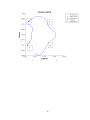
1) Flight #8
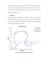
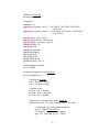
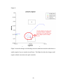
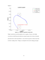
Flight #8 was the first successful flight to navigate four waypoints successfully. Figure
5.1 and Figure 5.2 contain the plot of latitude and longitude for this flight. In Figure 5.1,
the boxes around each waypoint represent the maximum allowable error used to declare
that the aircraft has made it to the waypoint. As soon as the aircraft position is within the
box, the next waypoint is loaded. The boxes used for this demonstration were drawn at
0.00025 degrees of latitude and 0.00025 degrees of longitude. This corresponds to
roughly 90 feet in latitude and 75 feet in longitude (estimated using 34 degrees latitude).
This means that the maximum distance the aircraft can be from the waypoint and still
declare that it has arrived is ~117 feet (in the corners).
21
Figure 5.1: Flight #8 Latitude/Longitude Plot
22
Figure 5.2: Flight #8 Map Plot
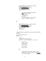
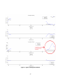
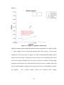
Plots of desired heading vs true heading and desired altitude vs true altitude along with
the servo inputs are shown in Figure 5.3. The altitude plot shows that the aircraft was
entering into an oscillatory state just prior to reaching the final waypoint. In addition, the
heading tracking algorithm caused the plane to overshoot the desired heading on multiple
occasions.
However, the simple navigation algorithms were sufficient enough to
complete
the
navigation
of
waypoints
23
for
the
small
aircraft.
Figure 5.3: Flight #8 Heading and Altitude data
24
Following flight #8, small adjustments to the control logic for the rudder and the elevator
were made. These adjustments added additional throw to the rudder and reduced the
throw of the elevator. This data was shown previously in Figure 4.4 and Figure 4.5 in the
software section of this report.
2) Flight #9
During flight #9, all four waypoints were reached successfully, however, this flight
demonstrated the ability of the system to spin the aircraft to reach a missed waypoint.
Figure 5.5 shows that the altitude and heading were much steadier than in flight #8 and
the large altitude oscillations were eliminated.
Figure 5.4: Flight #9 Latitude/Longitude Plot
25
Figure 5.5: Flight #9 Heading and Altitude data
26
3) Flight #10
No changes to the navigation software were made between flight #9 and flight #10.
Flight #10 completely demonstrated the FPGA navigation system by successfully flying
through each waypoint without having to loop back after missing one. High winds
existed during this flight (10~12 mph) which is evident in the oscillations in altitude
during sharper turns. Even so, the system was able to withstand these sharp losses in
altitude and recovers the lost altitude in less than 10 seconds.
Figure 5.6: Flight #10 Latitude/Longitude Plot
27
Figure 5.7: Flight #10 Heading and Altitude data
28
VI.
CONCLUSIONS
Using very simple control algorithms with assistance of a flight stabilization device the
navigation of the small aircraft using only a GPS receiver and FPGA board was
successful. Several other projects have been completed by others which accomplish
similar objectives ([6], [7], [8], and [9]). The differences between these projects and this
one are the integration of an FPGA board into the navigation processing and the custom
navigation algorithms running on the FPGA board.
There were several limitations
encountered during the execution of this project, including wind speed at the flying
location and quality of the infrared sensor calibration. GPS dropouts were the only issues
discovered during this project. Improvements to the control surface algorithms can be
improved with additional sensors.
1) Limitations
Wind speeds were a major limitation to this project. Because the aircraft was rather
small, it was susceptible to all wind.
Flight tests occurred in the high deserts of
California near Lancaster. In this area, the winds can reach 30 mph on a regular basis.
Take-offs and landings were difficult in winds any greater than ~10 mph. At these wind
speeds, the navigation algorithms were ineffective and could not turn the aircraft
sufficiently using only the rudder. Aileron inputs are required for wind speeds above 10
mph and therefore additional sensors are required.
The quality of the flight was highly dependent on the quality of calibration of the infrared
sensors. Before each flight, the sensors required calibration to set the level of heat
emitting from the ground compared to the temperature of the atmosphere. Each time the
29
calibration takes place, the device response with a calibration rating of 1 to 10 (10 being
the best). The aircraft with a calibration rating of 5 or less would get into a spin
immediately following the activation of the navigation system. The optimal calibration
rating was an 8 or better. With this rating the aircraft could maintain level flight even
with drastic rudder inputs.
2) Issues
Initial testing of the FPGA board controlling the servos had GPS dropouts in which the
GPS would lose signal with the GPS satellites. It was discovered that the servos draw a
significant amount of current when actuated and the GPS would momentarily lose power
causing it to reset. The addition of a second battery was required to create power
isolation from the servos and the DE0-nano FPGA board.
3) Improvements
Navigation algorithms could be improved by introducing additional sensors on the
aircraft. Replacing the infrared flight stabilization system with a more robust
accelerometer and gyroscope inertial navigation system (INS) would allow the user to
program specific turning geometries to allow the aircraft to turn faster and track better to
the desired heading. In addition, the attitude of the aircraft would be known which would
allow for better rudder, elevator, and aileron control logic.
30
REFERENCES
[1] Co-Pilot Infrared Flight Stabilization System User’s Guide (2003) [ONLINE]
Available: http://www.revolectrix.com/support_docs/item_1126.pdf
[2] DE0-Nano User Manual v1.9 (2013) [ONLINE] Available:
http://www.terasic.com.tw/cgi-bin/page/archive_download.pl?Language=English&
No=593&FID=75023fa36c9bf8639384f942e65a46f3
[3] U-blox 6 Receiver Description Including Protocol Specification (2013) [ONLINE]
Available:http://www.u-blox.com/images/downloads/Product_Docs/u-blox6_Receiver
DescriptionProtocolSpec_%28GPS.G6-SW-10018%29.pdf
[4] Embedded Peripherals IP User Guide (2011) [ONLINE] Available:
www.altera.com/literature/ug/ug_embedded_ip.pdf
[5] Serial Configuration (EPCS) Devices Datasheet (2014) [ONLINE] Available:
www.altera.com/literature/hb/cfg/cyc_c51014.pdf
[6] Haiyang Chao, Yongcan Cao, YangQuan Chen, Autopilots for Small Fixed-Wing
Unmanned Air Vehicles: A Survey, 2007
[7] Young-Eun Song and Kwang-Joon Yoon, Development of a Small Air Robot with
Fixed Wing and Semi-Autopilot System, 2007
[8] Xiaojing Du Dacheng Du Kang Wang, Position Accuracy Evaluation of GPS
Receiver under Small UAV Flight Environment, 2009
[9] David Erdos, and Steve E. Watkins, UAV Autopilot Integration and Testing, 2008
31
APPENDICES
Appendix A: GPS Message Definitions
32
33
Appendix B: Qsys Setup
NIOS II Processor
34
Onchip Memory
The on-chip memory must be large enough to contain the navigation code. Be sure to
adjust the “Total Memory Size” to accommodate the size of the code. Also, make sure
the data width matches that of the chip set on the FPGA board being used.
35
JTAG-UART
Use the default settings for this component. It will provide communications between the
computer and the FPGA chip for programming and debugging.
36
SYS-ID – Use default settings
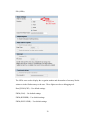
UART RS-232 (GPS)
For this project, the Neo-6m GPS module was programmed to operate at 38400 baud rate
and the basic settings seen above. Be sure to match these parameters to the GPS being
utilized.
37
EPCS Flash Controller
Be sure to check the active serial interface checkbox.
38
PIO (LEDs)
The LEDs were used to display the waypoint number and the number of memory blocks
written to in the flash memory to the user. These lights served as a debugging tool.
Read_PWM (CH5) – Use default settings
PWM (GAS) – Use default settings
PWM (RUDDER) – Use default settings
PWM (ELEVATOR) – Use default settings
39
Appendix C: PWM Generator VHDL Code
------------------------------------------ PWM Generator
-- Ben Criel
-- Updated: 3/31/14
-- CSUN Graduate Project
------------------------------------------ The purpose of this VHDL code is to generate PWM
-- signals based on user input.
-- Input Register: writedata
-- Output Register: readdata
-- Input: pwm_in = intput PWM signal from radio
-- Output: pwm_out = output PWM signal from FPGA
-- Based on three registers:
-- enable_register, clock_divide_register, and duty_cycle_register
-- When enabled, a PWM signal is created with
-- Period of count = clock_divide_register and
-- with duty cycle = duty_cycle_register
-- If disabled, pwm_out = pwm_in and the pwm generator is bypassed
----------------------------------------LIBRARY IEEE;
USE IEEE.STD_LOGIC_1164.all;
USE IEEE.std_logic_unsigned.all;
entity pwm is
PORT(
clk,resetn,CS,write,read : IN STD_LOGIC;
address : IN STD_LOGIC_VECTOR(1 DOWNTO 0);
writedata : IN STD_LOGIC_VECTOR(31 DOWNTO 0);
pwm_in : IN STD_LOGIC;
pwm_out : OUT STD_LOGIC;
readdata : OUT STD_LOGIC_VECTOR(31 DOWNTO 0));
END pwm;
ARCHITECTURE arch of pwm is
40
-- validity signals
SIGNAL valid_write : STD_LOGIC;
SIGNAL valid_read : STD_LOGIC;
-- select lines
SIGNAL clock_divide_register_select : STD_LOGIC;
SIGNAL duty_cycle_register_select : STD_LOGIC;
SIGNAL enable_register_select
: STD_LOGIC;
-- REGISTERS
SIGNAL enable_register : STD_LOGIC;
SIGNAL clock_divide_register : STD_LOGIC_VECTOR(31 DOWNTO 0);
SIGNAL duty_cycle_register : STD_LOGIC_VECTOR(31 DOWNTO 0);
BEGIN
--decode address
clock_divide_register_select <= NOT(address(1)) AND NOT(address(0));
duty_cycle_register_select <= NOT(address(1)) AND address(0);
enable_register_select <= address(1) AND NOT(address(0));
valid_write <= CS AND write;
valid_read <= CS AND read;
PROCESS(clk)
BEGIN
-- Update the clock_divide_register with writedata
IF(rising_edge(clk))THEN
IF(resetn = '0')THEN
clock_divide_register <= (others => '0'); -- clock divide reset
ELSIF(valid_write = '1' AND clock_divide_register_select = '1')THEN
clock_divide_register <= writedata;
END IF;
END IF;
-- Update the Duty_cycle_register with writedata
IF(rising_edge(clk))THEN
IF(resetn = '0')THEN
duty_cycle_register <= (others => '0'); -- duty cycle reset
ELSIF(valid_write = '1' AND duty_cycle_register_select = '1')THEN
duty_cycle_register <= writedata;
END IF;
41
END IF;
-- Update the enable_register with writedata
IF(rising_edge(clk))THEN
IF(resetn = '0')THEN
enable_register <= '0'; --enable reset
ELSIF(valid_write = '1' AND enable_register_select = '1')THEN
enable_register <= writedata(0);
END IF;
END IF;
END PROCESS;
--read current duty cycle or period of PWM signal
readdata <=
clock_divide_register WHEN((valid_read AND clock_divide_register_select) = '1')
ELSE
duty_cycle_register WHEN((valid_read AND duty_cycle_register_select) = '1') ELSE
(others => '0');
PROCESS(clk)
VARIABLE count : STD_LOGIC_VECTOR(31 DOWNTO 0);
BEGIN
IF(rising_edge(clk))THEN
IF(resetn = '0')THEN --reset outputs
count := (others => '0');
pwm_out <= '0';
ELSIF(enable_register = '1')THEN
IF(count < clock_divide_register)THEN -- count clock cycles
count := count + 1;
ELSE
count := (others => '0'); -- end of cycle... reset
END IF;
IF(count < duty_cycle_register)THEN
pwm_out <= '1'; --output high value
ELSE
pwm_out <= '0'; --output low value
END IF;
ELSE
pwm_out <= pwm_in; --bypass PWM generator
END IF;
END IF;
END PROCESS;
END arch;
42
Appendix D: PWM Measurement VHDL Code
------------------------------------------ PWM Measurement
-- Ben Criel
-- Updated: 3/31/14
-- CSUN Graduate Project
------------------------------------------ The purpose of this VHDL code is to measure PWM
-- signals.
-- Input Register: writedata
-- Output Register: readdata
-- Input: pwm_in = intput PWM signal from radio
-- Hardcoded is a clock count value of 925000.
-- This value represents the period of the PWM signal
-- to be measured. 925000 clock counts of a 50MHz
-- clock is 18.5ms. This is the measured period for
-- the PWM signals from the 6EXP radio/receiver.
-- The readdata register is filled with the number of
-- clock counts that occur while the PWM_in signal
-- is a value of '1'. This is updated every 925000 clock counts
----------------------------------------LIBRARY IEEE;
USE IEEE.STD_LOGIC_1164.all;
USE IEEE.std_logic_unsigned.all;
entity read_pwm is
PORT(
clk,resetn,CS,write,read : IN STD_LOGIC;
address : IN STD_LOGIC_VECTOR(1 DOWNTO 0);
writedata : IN STD_LOGIC_VECTOR(31 DOWNTO 0);
pwm_in : IN STD_LOGIC;
readdata : OUT STD_LOGIC_VECTOR(31 DOWNTO 0));
END read_pwm;
43
ARCHITECTURE arch of read_pwm is
SIGNAL valid_read : STD_LOGIC;
SIGNAL count_register : STD_LOGIC_VECTOR(31 DOWNTO 0);
BEGIN
valid_read <= CS AND read;
readdata <= count_register;
PROCESS(clk)
VARIABLE count : STD_LOGIC_VECTOR(31 DOWNTO 0);
VARIABLE samples : STD_LOGIC_VECTOR(31 DOWNTO 0);
BEGIN
IF(rising_edge(clk))THEN
samples := samples + 1;
IF(resetn = '0')THEN
count := (others => '0');
samples := (others => '0');
ELSIF(samples > 925000)THEN
count_register <= count;
count := (others => '0');
samples := (others => '0');
ELSIF(pwm_in = '1')THEN
count := count + 1;
END IF;
END IF;
END PROCESS;
END arch;
44
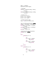
Appendix E: Navigation C Code
//////////////////////////////////////////////////////
// Small Aircraft GPS Navigation
// slowpoke.c
// Ben Criel
// Updated 3/31/14
//
// Functions:
// readGPS()
// INIT_FLASH()
// main()
//
// Under the main function the GPS is read and when an
// update occurs, the desired heading is calculated.
// Heading and Altitude errors are calculated, and
// the PWM registers are updated to attempt to correct
// the errors.
//
// The code drives the aircraft towards designated
// waypoints.
//
//
//////////////////////////////////////////////////////
#include "de0.h"
//servo period
#define period 1000000//20ms period
//center the servos
#define straight 75000
//maximum allowable waypoint error
#define del_limit 2500 //0.00025 deg or 75 feet
//GLOBAL VARIABLES
unsigned long iTow = 0;
signed long latitude = 346776360;
signed long longitude = -1182734800;
signed long altitude = 800000;
signed long heading = 90000;
//number of flash pages written to
unsigned long flashnum;
45
//define address in flash large enough
//not to overwrite program information
int epcsaddr = 0x140000;
//GPS update
int update;
//implement record on/off to not overwrite
//flash data on initial startup. This allows
//the data on flash to be read after each flight.
int record = 0;
////////////////////////////////////////////////
// readGPS function
// This function reads 8 bits from the GPS UART
// connection. Then based on a state machine
// outputs aircraft position information
// the bits are read in this order:
// Sync Char 1
// Sync Char 2
// Class
// ID
// Payload Length LSB
// Payload Length MSB
// Payload (number of bytes determined by “payload length”)
// Check Sum A
// Check Sum B
//
// Global variables are updated after successfully
// reading a full message.
////////////////////////////////////////////////
void readGPS()
{
unsigned int data[50];
int done=0;
unsigned long b=0,a=0;
int state=1,i=1;
unsigned int msg_length=0;
unsigned int msg_type=0;
unsigned int ck_a,ck_b;
unsigned int read;
46
unsigned int ROE;
unsigned int EOP;
unsigned int BRK;
unsigned int ERR;
done = 0;
while(done == 0)
{
b = IORD(GPS_BASE,2);
//printf("%lx\n",b);
read = b >> 7;
ROE = b >> 3;
EOP = b >> 12;
BRK = b >> 2;
ERR = b >> 8;
if(ERR & 1)
{
IOWR(GPS_BASE,2,0x00000000);
//printf("b : %4lx : reset\n",b);
}
if(read & 1)
{
a = IORD(GPS_BASE,0);
a = a & 0xFF;
//printf("%04lx ",a);
switch(state)
{
case 1:
i = 0;
if(a == 0xB5) state = 2; //UBX MSG #1
else state = 1; //bad message
break;
case 2:
if(a == 0x62) state = 3; //UBX MSG #2
else //bad message
{
state = 1;
done = 1;
}
break;
case 3:
47
if(a == 0x01) state = 4; //NAV Messages
else //bad message
{
state = 1;
done = 1;
}
break;
case 4:
if(a == 0x02) //LAT-LONG
{
msg_type = 1;
state = 5;
}
else if(a == 0x12) //Heading
{
msg_type = 2;
state = 5;
}
else //bad message
{
state = 1;
done = 1;
}
break;
case 5: //length1
msg_length = a;
state = 6;
break;
case 6: //length2
msg_length = msg_length + (a << 8);
state = 7;
break;
case 7: //payload
data[i] = a;
i = i+1;
if(i == msg_length)
break;
case 8: //checksum1
ck_a = a;
state = 9;
break;
48
state = 8;
case 9: //checksum2
ck_b = a;
state = 1;
switch(msg_type)
{
case 1:
//fix longitude to display negative values
if(data[7] > 0x80)
{
longitude = (data[4] + (data[5] << 8) + (data[6]
<< 16) + (data[7] << 24)) - 0xFFFFFFFF
+ 0x01;
}
else
{
longitude = 0xFFFFFFFF - (data[4] + (data[5] << 8)
+ (data[6] << 16) + (data[7] << 24)) + 0x01;
}
latitude = (data[8] + (data[9] << 8) + (data[10]
<< 16) + (data[11] << 24));
altitude = (data[12] + (data[13] << 8) + (data[14]
<< 16) + (data[15] << 24));
iTow = (data[0] + (data[1] << 8) + (data[2] << 16)
+ (data[3] << 24));
state = 1;
break;
case 2:
heading = (data[24] + (data[25] << 8) + (data[26]
<< 16) + (data[27] << 24));
update = 1;
done = 1;
break;
}
break;
}
}
else
{
update = 0;
}
49
}
}
////////////////////////////////////////////////
// INIT_FLASH function
// This function is called at the beginning of the main
// program to initialize the flash memory for storage
// of flight data information.
//
// Function clears enough room for 10000 data points
// of 14 parameters with lengths of 32 bits.
//
// global variable record is set to ‘1’ to begin recording.
////////////////////////////////////////////////
void INIT_FLASH()
{
alt_flash_dev *pFlash;
pFlash = alt_flash_open_dev(FLASH_NAME);
//Clear room for 10000 data points of 14 32-bit parameters
alt_erase_flash_block(pFlash,epcsaddr,0x88B80);
//Enable data recording
record = 1;
}
50
////////////////////////////////////////////////
// MAIN function
// This function is the main function for navigation
//
// First initialization of flash memory and PWM signals
// takes place. Waypoints are entered in this function.
// An outside for loop runs through each waypoint and a
// while loop inside the for loop runs until the current
// waypoint is reached. Inside the while loop the gps is
// read and the PWM signals are updated accordingly.
// When the last waypoint is reached. The program leaves
// the for loop and enters into an infinite while loop where
// the gps continues to be read and data continues to be
// stored to the flash memory.
////////////////////////////////////////////////
int main(void)
{
//Enable Flash Memory
alt_flash_dev *pFlash;
pFlash = alt_flash_open_dev(FLASH_NAME);
int j,k;
unsigned long lights=0;
//INITIALIZE SERVOS TO CENTER
/////////////////////////////////
IOWR(RUDDER_BASE,2,0x0); // disable
IOWR(RUDDER_BASE,0,period); // set period
IOWR(RUDDER_BASE,1,straight); // center servo
IOWR(RUDDER_BASE,2,0x1); // enable
IOWR(GAS_BASE,2,0x0); // disable
IOWR(GAS_BASE,0,period); // set period
IOWR(GAS_BASE,1,straight); // center servo
IOWR(GAS_BASE,2,0x1); // enable
IOWR(ELEVATOR_BASE,2,0x0); // disable
IOWR(ELEVATOR_BASE,0,period); // set period
IOWR(ELEVATOR_BASE,1,straight); // center servo
IOWR(ELEVATOR_BASE,2,0x1); // enable
/////////////////////////////////
//wait
usleep(1000000);
51
//number of waypoints
int numpoints;
//Waypoints
numpoints = 4;
signed long Waypoint_Lat[4] = { 346769870, 346792280, 346792650,
346767360};
signed long Waypoint_Lon[4] = {-1182704040,-1182704870,-1182725920,1182725360};
signed long Lat_f,Lon_f,Alt_f;
signed long del_Lat,del_Lon,del_Alt;
signed long prev_lat=10,prev_lon=10;
signed long Hdg_f=0;
signed long error;
signed long writedata;
signed long steering;
signed long pitch;
signed long speed;
unsigned long on_off;
signed long NAV_ON = 0;
//Assign temporary altitude
Alt_f = 850000;
//complete navigation for each waypoint
for(j=0;j<numpoints;j++)
{
//assign next waypoint
Lat_f = Waypoint_Lat[j];
Lon_f = Waypoint_Lon[j];
//calculate errors
del_Lat = Lat_f - latitude;
del_Lon = Lon_f - longitude;
del_Alt = Alt_f - altitude;
//check to see if aircraft is near current waypoint
while(abs(del_Lat) > del_limit || abs(del_Lon) > del_limit)
{
//read channel 5 for enable bit for navigation
on_off = IORD(CH5_BASE,0);
//if channel 5 is "up" turn on navigation
if(on_off < 55000 && on_off > 45000)
{
52
//enable PWM generator registers for navigation
IOWR(RUDDER_BASE,2,0x1);
IOWR(ELEVATOR_BASE,2,0x1);
IOWR(GAS_BASE,2,0x1);
if(NAV_ON == 0)
{
//use current altitude as desired altitude
//aka hold current altitude
Alt_f = altitude;
//navigation is on
NAV_ON = 1;
//if not recording data... start recording
if(record == 0) INIT_FLASH();
}
}
else
{
//disable PWM generators and enable pass-thru
IOWR(RUDDER_BASE,2,0x0);
IOWR(ELEVATOR_BASE,2,0x0);
IOWR(GAS_BASE,2,0x0);
//navigation off
NAV_ON = 0;
}
//READ CURRENT AIRCRAFT LOCATION DATA FROM GPS
readGPS();
//If good data read from GPS
if(update == 1)
{
update = 0;
// CHECK FOR GPS DROP-OUT
if((latitude == prev_lat) & (longitude == prev_lon))
{
//spin to left
steering = 100000;
//hold altitude
pitch = straight;
// 3/4 throttle
speed = 70000;
}
else
{
//update lights to show number of pages in flash
//that have been written to and the current waypoint
//the aircraft is flying to.
53
lights = j + flashnum;
IOWR(LEDS_BASE,0,lights);
// fix heading
if(heading > 18000000) heading = heading
- 36000000;
if(heading < -18000000) heading = heading
+ 36000000;
// Calculate errors
del_Lat = Lat_f - latitude;
del_Lon = Lon_f - longitude;
del_Alt = Alt_f - altitude;
// Calculate temporary angle
Hdg_f = abs(del_Lat*1000/del_Lon);
//piece-wise linear approximation to arctan
if(Hdg_f > 10000) Hdg_f = 9000000;
else if(Hdg_f > 3410) Hdg_f = 150*Hdg_f
+ 7100000;
else if(Hdg_f > 890) Hdg_f = 1000*Hdg_f
+ 4200000;
else Hdg_f = Hdg_f*5730;
//apply appropriate signage for quadrant
switch(del_Lon >= 0)
{
case 1:
switch(del_Lat >= 0)
{
//Q1
case 1: Hdg_f = 9000000
- Hdg_f;break;
//Q4
case 0: Hdg_f = 9000000
+ Hdg_f;break;
}
break;
case 0:
switch(del_Lat >= 0)
{
//Q2
case 1: Hdg_f = -9000000
+ Hdg_f;break;
//Q3
54
case 0: Hdg_f = -9000000
- Hdg_f;break;
}
break;
}
//fix desired heading
if(Hdg_f > 18000000) Hdg_f = Hdg_f - 36000000;
if(Hdg_f < -18000000) Hdg_f = Hdg_f + 36000000;
//calculate heading error
error = Hdg_f - heading;
//fix heading error
if(error > 18000000) error = error - 36000000;
if(error < -18000000) error = error + 36000000;
//Update rudder angle
steering = straight +
error*10/12000000*2500;
if(steering > 100000)steering=100000;
if(steering < 50000) steering=50000;
//Update elevator
pitch = straight +
del_Alt*10/75000*2500;
if(pitch > 100000) pitch = 100000;
if(pitch < 50000) pitch = 50000;
//Update speed
speed = 70000;
}
//UPDATE PWM SIGNALS
IOWR(RUDDER_BASE,1,steering);
IOWR(ELEVATOR_BASE,1,pitch);
IOWR(GAS_BASE,1,speed);
//STORE LAT LON FOR COMPARE
prev_lat = latitude;
prev_lon = longitude;
//write current location data to flash
if(record == 1)
{
for(k=0;k<13;k++)
55
{
switch(k)
{
case 0: writedata = iTow;break;
case 1: writedata = longitude;break;
case 2: writedata = latitude;break;
case 3: writedata = altitude;break;
case 4: writedata = heading;break;
case 5: writedata = Lon_f;break;
case 6: writedata = Lat_f;break;
case 7: writedata = Alt_f;break;
case 8: writedata = Hdg_f;break;
case 9: writedata = pitch;break;
case 10: writedata = steering;break;
case 11: writedata = speed;break;
case 12: writedata = NAV_ON;break;
}
if(address+4 > epcsaddr + 0x10000)
{
epcsaddr += 0x10000;
address = 0;
flashnum += 16;
}
alt_write_flash_block(pFlash,epcsaddr,
epcsaddr + address,&writedata,4);
address = address + 4;
}
}
}
}
}
//STOP
/////////////////////////////////
NAV_ON = 0;
IOWR(RUDDER_BASE,2,0x0);
IOWR(ELEVATOR_BASE,2,0x0);
IOWR(GAS_BASE,2,0x0);
//writeflash();
IOWR(LEDS_BASE,0,255);
//printf("done\n");
/////////////////////////////////
//Continue to record location data even though the final
//waypoint has been reached
56
while(1)
{
//READ CURRENT AIRCRAFT LOCATION DATA FROM GPS
readGPS();
if(update == 1)
{
if(record == 1)
{
//write current location data to flash
for(k=0;k<13;k++)
{
switch(k)
{
case 0: writedata = iTow;break;
case 1: writedata = longitude;break;
case 2: writedata = latitude;break;
case 3: writedata = altitude;break;
case 4: writedata = heading;break;
case 5: writedata = Lon_f;break;
case 6: writedata = Lat_f;break;
case 7: writedata = Alt_f;break;
case 8: writedata = Hdg_f;break;
case 9: writedata = pitch;break;
case 10: writedata = steering;break;
case 11: writedata = speed;break;
case 12: writedata = NAV_ON;break;
}
if(address+4 > epcsaddr + 0x10000)
{
epcsaddr += 0x10000;
address = 0;
flashnum += 16;
}
alt_write_flash_block(pFlash,epcsaddr,
epcsaddr + address,&writedata,4);
address = address + 4;
}
}
}
}
return 0;
57
}
Appendix F: C Code Header File
#include <stdio.h>
#include <stdlib.h>
#include <stdbool.h>
#include <io.h>
#include "alt_types.h"
#include "sys/alt_irq.h"
#include "system.h"
#include "sys/alt_stdio.h"
#include "alt_types.h"
#include "altera_avalon_spi_regs.h"
#include "altera_avalon_spi.h"
#include "altera_avalon_pio_regs.h"
#include "sys/alt_flash_dev.h"
#include "sys/alt_flash.h"
#include "altera_avalon_timer_regs.h"
58
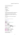
Appendix G: Early Flight Data
This appendix contains flight data from early flights. The information gained during data
review of these flights went towards developing changes to navigation and aircraft
control algorithms. More than 20 flight tests were completed. Several early flights
included quality of flight tests to determine the stability of the aircraft and to ensure the
flight stabilization Co-Pilot device was working properly. The next phase of flight
testing included using the FPGA for navigation, but storing data in SDRAM which would
be erased as soon as the board was powered off. This resulted in several flights using
FPGA navigation but without any recorded data. The following flight data shows the
flights in which data was retrieved from the FPGA board after switching data storage to
the flash memory.
Data was recorded for flights 1-4, but errors in the navigation
algorithm resulted in unsuccessful flight data and are therefore not shown.
59
Flight #5:
Figure G.1: Flight #5 Latitude/Longitude Data
Flight 5 resulted in changes to the heading correction which increased the rudder throw at
smaller angles of error to turn the aircraft faster. This flight also led to the change to add
negative altitude correction to the pitch controller.
60
Figure G.2: Flight #5 Heading and Altitude data
61
Flight #6:
Figure G.3: Flight #6 Longitude/Latitude Data
Flight 6 resulted in successful navigation of two waypoints. However, the altitude
correction was insufficient and resulted in no negative inputs to the elevator to bring the
plane back down to the desired altitude. Also, the final waypoint was almost missed due
to the slow turning aircraft. Changes were adopted to increase the turning speed again.
62
Figure G.4: Flight #6 Heading and Altitude data
63
Flight #7:
Figure G.5: Flight #7 Longitude/Latitude Data
Significant changes to the heading and altitude correction algorithms were made for flight
7. These changes were to increase the turning ability of the aircraft. If the aircraft
heading was off by more than 10 degrees, the FPGA commanded full rudder (left or
right) to turn the aircraft. Turning any aircraft results in loss of altitude unless small
corrections are made with the elevator to correct for this loss of altitude. For this flight,
the inputs to the elevator were either full elevator (up or down) or centered. When full
elevator and full rudder are applied at the same time, the result is a spiraling dive towards
the
ground.
The
Co-Pilot
system
64
could
not
overcome
these
inputs.
Figure G.6: Flight #7 Heading and Altitude data
65