1
SciFlex™ 140 NFF Operations Manual
SL-4-11-9000401-4, Copyright 2012 SciLog Inc.
SciLog Inc.
05/2012, Rev. 4
(This Page Intentionally Left Blank)
~2~
PRECAUTIONS:
READ this manual BEFORE
operating or servicing this
equipment.
FOLLOW these instructions
carefully.
SAVE this manual for future
reference.
DO NOT allow untrained
personnel to operate, clean,
inspect, service or tamper with
this equipment.
ALWAYS DISCONNECT this
equipment from the power source
before cleaning or performing
maintenance.
CALL SCILOG for parts, information and service.
~3~
PRÉCAUTIONS:
LISEZ ce manuel AVANT de faire
fonctionner ou d’entretenir cet
équipement.
SUIVEZ attentivement ces
instructions.
CONSERVEZ ce manuel pour
future référence.
NE LAISSEZ PAS du personnel non
qualifié utiliser, nettoyer, inspecter,
entretenir, réparer ou manipuler cet
équipement.
DÉBRANCHEZ TOUJOURS cet
équipement de la source de courant
avant de nettoyer ou
d’exécuter l’entretien.
APPELEZ SCILOG pour pièces
détachées, renseignements et
entretien.
~4~
Table of Contents
PRECAUTIONS: .............................................................................................................. 3
PRÉCAUTIONS: .............................................................................................................. 4
Table of Contents ........................................................................................................... 5
Safety Information:......................................................................................................... 6
Installation & Start-Up: .................................................................................................. 7
Maintenance & Cleaning: ............................................................................................... 7
Introduction: ................................................................................................................... 8
SciFlex 140-NFF Specifications: ................................................................................. 11
Part A: SciFlex™ Hardware: ....................................................................................... 12
1.0 Overview: ................................................................................................................ 12
2.0 Front Panel: Data Entry & Display: ...................................................................... 13
3.0 Interface Options: ................................................................................................... 13
4.0 Filtrate and or Feed Scale: .................................................................................... 14
5.0 Pressure Sensor Installation: ................................................................................ 15
6.0 System Feed Pump Head: ..................................................................................... 15
Part B: SciFlex NFF Software .................................................................................. 16
1.0 Home Screen: ......................................................................................................... 16
2.0 Setup Screens: ....................................................................................................... 18
3.0 Constant Rate Screen: ........................................................................................... 21
4.0 Constant Pressure Screen:.................................................................................... 22
5.0 RP Stat Screen: ...................................................................................................... 23
6.0 Run Screen: ............................................................................................................ 24
6.0 Alarm Screen: ......................................................................................................... 26
7.0 Trending Screen: .................................................................................................... 27
8.0 Manual Mode Screen:............................................................................................. 28
7.0 Data Collection: ...................................................................................................... 29
8.0 End User License Agreement: ............................................................................... 30
Appendix A: Watson Marlow 620RE4/R Pump Head Manual .................................... 33
Appendix B: Levitronix Puralev® 200 SU Manual ....................................................... 34
Appendix C: Viking Acculobe Manual ........................................................................ 35
~5~
Safety Information:
Be sure to read and observe the following requirements!
Before connecting the SciFlex to mains, make sure that the mains voltage
corresponds to the voltage rating shown on the nameplate.
Opening the SciFlex electronics enclosure cover exposes live parts.
Therefore, the cover must not be removed. If repair should be required,
return the SciFlex electronic enclosure to the factory.
If opening of the SciFlex electronics enclosure is inevitable, the system
must first be disconnected from all voltage sources.
Make sure that the mains plug has been pulled out.
Repair or adjustment of an opened SciFlex electronics enclosure under
voltage must be carried out only by a skilled person who is aware of the
hazard involved.
Whenever it is likely that the protection has been impaired, the SciFlex
must be made inoperative and secured against any unintended operation.
The protection is likely to be impaired if, for example:
The SciFlex shows visible damage
The SciFlex fails to perform as intended
After prolonged storage above 70C
After severe transport stresses
Before re-commissioning the SciFlex, a professional routine test according
to the SciFlex IQ/OQ Protocols must be performed.
~6~
Installation & Start-Up:
Installation of the SciFlex™ System must be carried out only by trained
personnel in accordance with the relevant regulations and this operations
manual.
Make sure that the technical specifications and input ratings of the SciFlex™ are
observed. See “SciFlex™ Specifications”.
The protection provided by this equipment may be impaired if the SciFlex™ is
used in a manner inconsistent with this manual or for purposes not specified by
the manufacturer.
Maintenance & Cleaning:
The SciFlex™ is practically maintenance free. The SciPres™ Disposable
Sensors used with the system come pre-calibrated from the factory and require
no maintenance.
To remove dust, dirt and stains, the outer surfaces of the SciFlex™ may be
wiped using a soft, non-fluffing cloth moistened with water. If required, you may
also use a mild detergent or 2-propanol.
The SciPres™ Disposable Sensors may be sanitized with 0.1 Molar NaOH, or 2propanol. They may be autoclaved up to twice, and newer units with the grey
rings around the cable connector may be gamma irradiated. Additional Sensors
may be ordered from SciLog when needed, available in 5 packs. SciPres ¾ “
TC: PN 080-696PSX-5.
Description of this Manual:
The following information is covered in this Manual:
Safety Requirements
Product Specifications
Hardware Description
NOTE:
Note calls attention to important information. Italics are used to further
emphasize certain information. Ignoring the given instructions may lead to
malfunction or damage of the instrument or other equipment and to
personal injury.
~7~
Introduction:
You will find the SciFlex™ System easy to use. The state-of-the-art hardware and
software design of the SciFlex™ allows you to control measure and document your
Normal Flow Filtration / Dispensing processes. With proper maintenance, the SciFlex™
NFF System will provide many years of excellent service and performance.
Please read the following instructions carefully!
Inspections: Refer to the separate unpacking document, and remove the SciFlex and
accessories carefully from the shipping container. Check the contents against the
purchase order to verify that all parts are included and undamaged.
Please do the inspection now, even if the SciFlex is not used immediately. Many carriers
must receive damage claims within seven days of delivery. Please retain all packing
material so unit may be shipped safely, if necessary.
SciLog Customer Service: If assistance is required, please contact us at:
SciLog Inc.
801 Deming Way (Shipping: 8446 Excelsior Dr.)
Madison, WI 53717
Phone: 800-955-1993 or 608-824-0500
Fax: 608-824-0509
SciLog Customer Service personnel will be able to serve you more efficiently if you have
the following information:
Serial number and model name of the equipment.
Installation procedure being used.
Concise list of symptoms.
List of operating procedures and conditions in use when problem arose.
Standards:
The SciFlex™ conforms to the following standards:
EN 61326-1:2006, Class B
EN 6100-3-2:2006
EN 6100-3-3:1995 +A1:2001 +A2:2006
EN 61010-1 Issued: 2001/03/01
UL 61010-1 Issued: 2004/07/12 Ed.2
And is certified to: CAN/CSA-C22.2 No 61010-1 Ed.2
~8~
Warranty Information:
SciLog LIMITED WARRANTY, LIMITATION OF LIABILITY & ACCEPTABLE USE
AGREEMENT
This Agreement is hereby entered into between You, the Buyer, and SciLog, Inc.
If you do not Agree to these terms, return the item to SciLog
1. LIMITED WARRANTY: SCILOG, INC. EXPRESSLY WARRANTS THE EQUIPMENT
MANUFACTURED BY IT ONLY AS SET FORTH HEREIN. SCILOG, INC. MAKES NO
OTHER WARRANTIES, EITHER EXPRESS OR IMPLIED (INCLUDING WITHOUT
LIMITATION WARRANTIES AS TO MERCHANTABILITY OR FITNESS FOR A
PARTICULAR PURPOSE). IN ADDITION, THE FOLLOWING SHALL CONSTITUTE
THE SOLE AND EXCLUSIVE REMEDIES OF BUYER FOR ANY BREACH BY SCILOG,
INC. OF ITS WARRANTY HEREUNDER.
a. PRODUCT WARRANTY – SciLog, Inc. warrants products it manufactures
against defects in materials and workmanship for one (1) year from the date of
shipment from SciLog, Inc. in normal use and service. If any products fail to
conform to this warranty within the first ninety (90) days of the warranty period,
SciLog, Inc. will, at its option, repair or replace such goods returned to SciLog. If
any products fail to conform to this warranty for the remainder of the warranty
period, SciLog, Inc. shall furnish necessary replacement parts free of charge.
b. PARTS WARRANTY -SciLog, Inc. warrants service parts against defects in
materials and workmanship for ninety (90) days from the date of shipment from
SciLog, Inc. in normal use and service. If any service parts fail to conform to this
warranty, SciLog, Inc. shall furnish necessary replacement parts free of charge.
c. WARRANTY LIMITATIONS -These warranties are subject to the following
conditions:
i. Product warranty shall only apply to the item as shipped by SciLog. Any
modifications to hardware, software, fluid line changes or any other
customer alteration which may affect the functionality of the product shall
not be covered by warranty.
ii. Upon discovery of product non-conformity, SciLog, Inc. will be given
prompt written notice with a detailed explanation of the alleged
deficiencies.
iii. The product or part must be properly installed, operated and maintained
in accordance with SciLog, Inc. specifications.
iv. The product or part must not be operated above rated load capacity or
subject to accident, alteration, misuse, or abuse.
v. The product must not have been repaired or serviced by anyone other
than SciLog, Inc. or one of its authorized dealers.
vi. SciLog, Inc. shall have a reasonable time to repair or replace the
defective product or part.
~9~
vii. The buyer is responsible for shipping the product or part to SciLog, Inc.
SciLog, Inc. is responsible for shipping the product back to the buyer.
2. INTELLECTUAL PROPERTY: The sale and delivery of the SciLog, Inc.’s equipment
and/or software to Buyer shall in no way transfer to Buyer any right of ownership in any
patents, copyrights, trademarks, technologies, designs, specifications, drawings, or other
intellectual property incorporated into the equipment and/or software.
3. DISCLAIMER OF DAMAGES: IN NO EVENT SHALL SCILOG, INC. BE LIABLE FOR
ANY TYPE OF SPECIAL CONSEQUENTIAL, INDIRECT, INCIDENTAL OR PENAL
DAMAGES, WHETHER SUCH DAMAGES ARISE OUT OF OR ARE A RESULT OF
BREACH OF CONTRACT, WARRANTY, TORT (INCLUDING NEGLIGENCE), STRICT
LIABILITY OR OTHERWISE. Such damages shall include but not be limited to loss of
profits or revenues, loss of use of the equipment or associated equipment, cost of
substitute equipment, damage to facilities, down time costs, increased production costs
or claims of Buyer's customers or contractors for such damages. Buyer agrees that in
the event of a transfer, assignment, or lease of the equipment sold hereunder Buyer
shall secure for the SciLog, Inc. the protection afforded to it in this paragraph.
4. LIMITATION OF LIABILITY: The SciLog, Inc. shall not be liable for any loss, claim,
expense or damage caused by, contributed to or arising out of the acts or omissions of
Buyer or third parties, whether negligent or otherwise. In no event shall the SciLog, Inc.'s
liability for any cause of action whatsoever exceed the replacement cost of the item
giving rise to the claim, whether based in contract, warranty, indemnity, or tort (including
negligence). Any suit arising hereunder must be commenced within one (1) year from
the date in which the cause of action accrues. Except as otherwise provided in the terms
of this Agreement SciLog, Inc. shall not indemnify any party for any reason.
5. NO RESPONSIBILITY FOR GRATUITOUS INFORMATION OR ASSISTANCE: If
SciLog, Inc. provides Buyer with assistance or advice which concerns any parts,
products, service supplied hereunder or any system or equipment in which any such
part, product or service may be installed and which is not required pursuant hereto, the
furnishing of such assistance or advice shall not subject SciLog, Inc. to any liability,
whether based in contract warranty, tort (including negligence) or otherwise.
6. INTERNATIONAL SALES / RESALE / EXPORT: Buyer EXPRESSLY agrees and
verifies that the purchased product(s) will not be transferred or exported to or purchased
on behalf of third parties and that Buyer is the final end-user of the product. Export or
transfer of any SciLog product without the express, written authorization of the SciLog,
Inc. is strictly prohibited and may violate US trade laws and regulations, thereby
subjecting the Buyer to civil and criminal liability.
7. REVISIONS TO THIS POLICY: From time to time SciLog, Inc. may revise the terms of
this Agreement. SciLog, Inc. will make its best efforts to inform customers of these
revisions. The most current revision of these terms may be accessed over the internet
by accessing the webpage located at: http://www.scilog.com/warranty
~ 10 ~
SciFlex 140-NFF Specifications:
Mechanical:
Dimensions: Length: 36 in. (91.4 cm); Width: 20 in. (51 cm); Height: 40 in. (102 cm).
Weight: 250 lb (114 Kg);
Enclosure:
Framework: Stainless Steel, Equipped with lockable 4” casters.
Control cabinet: Stainless Steel, with disconnect, on/off switch and E-Stop button.
Pump Head Options:
Watson Marlow 620RE4. Uses 12 or 17 mm BioPrene or Sta-Pure elemental tubing,
12 L/min. max. flow, 60 psi max.
Watson Marlow 620R Series, Continuous I/P tubing, #26, 83, 82 or 184, 30 psi max
Levitronix Puralev® 200 SU Pump Head system, 21 L/min. max at 36 psi. Has Single
Use replaceable pump head with 1/2” TC fittings.
Viking Acculobe 1:1 Rotary Lobe Pump Head, Tri-Wing design, 26 L/min. at 60 psi.
3/4" TC fittings, paired with a Micromotion F050 Coriolis Flow Meter for closed loop
pump rate control.
Pressure Sensors: Up to three SciPres Disposable Pressure Sensors, ¾” TC connections.
Polysulfone construction, 60 psi max., CIP, SIP, Autoclavable, Gamma Stable. P1 - located
in Filtrate, P2 and P3 available for filter train monitoring.
Electrical:
Power: 100/120 V~, Single Phase, 20 A Breaker, NEMA 5-20P plug. (208/240 V~, Single
Phase and 208 V~, Three Phase are available options)
Motor: Variable speed Lenze Servomotor, IP54 wash-down, continuous duty, 1 KW, 4096
INC Encoder for rpm feedback used with Watson Marlow heads. 1.6 KW unit is used with
the Viking Acculobe. Levitronix BSM 1.x motor, 24 VDC, 10,000 rpm max. is used with the
Levitronix Puralev® 200 SU head.
Filtrate and/or Feed Scale: SciLog WeighStation or other floor scale may be used
depending upon specific configuration.
Operating Range: 4 to 25 C.
Display, I/O:
10.4” Touch Screen Computer, On/Off switch and E-Stop button.
One network connection for use with an OPC client.
Software:
Main menu with five operational modes:
Constant Rate: Constant Rate Filtration user-definable alarms and end points.
Constant Pressure: Constant Pressure Filtration user-definable alarms and end points.
R/P Stat: Constant Rate / Constant Pressure Filtration that changes methods at a
defined pressure value, also with user-definable alarms and end points.
Manual: Manual set point of individual motors, no set point control.
Setup: Selection of user preferences, interface options, alarms and interlocks.
~ 11 ~
Data Collection :
The system contains an OPC server that may be connected to the customers OPC Data
Historian, such as OSI PI. An onboard CSV File is automatically populated on a USB
device attached to USB port 1 on the back of the touch panel interface. Retrieving the USB
should only be done with the unit switched off and power cord disconnected.
Part A: SciFlex™ Hardware:
1.0 Overview:
The SciFlex Model 140-NFF is a pilot plant-scale normal flow filtration system that enables
you to move, clarify, or sterilize solutions.
The SciFlex is designed to process volumes of material through a low shear peristaltic pump
and pressure sensor(s). The SciFlex-140 can include a SciLog Weigh Station for use with
Disposable Media bags as the Filtrate Vessel and or the Feed Vessel. An alternate Scale with
appropriately sized capacity and resolution can be used for your particular process.
Up to three pressures can be monitored with SciPres™ disposable Pressure Sensors. P1 is
used for measuring filter backpressure (plug-up) and filter trains are supported by the availability
of P2 and P3. The WeighStation or other electronic scale is connected to the SciFlex for
monitoring the quantitative collection of filtrate and its collection rate.
The SciFlex system provides ease of use and operational safety: Several user definable
end point conditions are continuously monitored and displayed. Global alarms as well as
physical interlocks are built into each system.
~ 12 ~
2.0 Front Panel: Data Entry & Display:
Emergency
Stop
Button
On / Off
Switch
The Front Panel has three components: A touch screen HMI, an On/Off switch, and an
Emergency Stop (E-Stop) Button.
The On/Off switch controls power to the screen and the bulk of the system. There is a master
On/Off switch on the cabinet door that shuts down all power.
The E-Stop button shuts down the motors and puts the system into a safe state without shutting
down the power. Useful if leaks or unexplained hi pressures occur.
The HMI is a touch screen panel and provides access to the SciFlex control software and all
modes and functions.
3.0 Interface Options:
Pressure: The SciFlex is equipped with three SciPres Disposable Pressure Sensors, installed
in the Feed, Retentate and Permeate lines. These are easily disconnected and replaced. They
use watertight cable connectors, and have ¾” TC fittings.
Ethernet: Used for connection to the SciFlex via a LAN for data collection. The unit can be
equipped with an Ethernet cable, and should be connected to the computer gathering the data
via a hub or switch. Contact SciLog for information on having this option installed.
~ 13 ~
4.0 Filtrate and or Feed Scale:
This SciFlex is typically paired with The SciLog WeighStation, a media bag holder with a 50 kg
capacity. This is typically used as the Filtrate scale, and can also be used as a Feed scale, or
both if desired. Other bench or floor scales, based upon purchased configuration, may also be
used.
~ 14 ~
5.0 Pressure Sensor Installation:
The SciPres Disposable Pressure Sensors are connected inline with the tubing and used in a flow through manner. The
SciPres Sensors have Polysulfone wetted surfaces that meet
all USP Class VI requirements.
The SciPres Disposable sensors are easy to change when
the need arises, and are readily available from SciLog in
packs of 5. They may be sanitized using several methods,
CIP with NaOH or alcohol, autoclaved up to twice, or gamma
irradiated. (Only those with grey rings around the connector
are gamma stable.)
6.0 System Feed Pump Head:
Currently, four options exist:
1. A Watson Marlow 620RE4 elemental tubing unit equipped with 12 mm or 17 mm BioPrene
or Sta-Pure tubing. Flows of up to 15 L/m are possible, with pressures of up to 60 psi.
2. A Watson Marlow 620R Continuous tubing unit equipped with I/P sized tubing is also an
option. Tubing sizes of #26, 73, 82 or 184 are possible, flows up to 12 L/m and pressures of
30 psi.
3. A Levitronix Puralev 200 SU motor/head system is an additional option. Max flow is 21 L/m
with max pressure of 36 psi.
4. A Viking Acculobe 1:1 Rotary Lobe Head, Tri-wing design head is the fourth option. Max
flow of 26 L/m, and max pressure of 60 psi. It is paired with a Micromotion F050 Coriolis
flow meter for closed loop control of the pump rate.
The flow rate range depends upon the unit installed, and is specified on the SETUP screen in
order to use the proper flow rate data.
~ 15 ~
Part B: SciFlex NFF Software
1.0 Home Screen:
The SciFlex has four operational modes screens, a run screen, alarms, trending and setup
screens as shown above.
NFF Modes:
This provides access to the three main Normal Flow Filtration Methods and their set points.
Recipes may also be created, saved, loaded, modified, and save again if desired.
Constant Rate (Feed rate) method where the feed rate is held constant until a pressure set
point is achieved,
Constant Pressure (Inlet) method where the feed rate is controlled to maintain a constant
filter backpressure until a low flow rate is achieved,
RP Stat method, where the two are combined. The system operates under Constant Rate
method and changes to Constant Pressure method at a pre-selected backpressure setting.
To create a recipe in these modes:
o Set the parameters listed on the Mode screen, enter a name for the recipe, and
click on the “save recipe” button. The name is appended with a time stamp.
To load a recipe:
o Click on the drop down box, tap on the recipe name, and then the “load recipe”
button. The selected recipe parameters will be loaded.
Manual Mode:
This mode allows the operator to set rate Feed Rate and run the system manually.
monitored values and alarms are available.
~ 16 ~
All
Run Screen:
A Run Screen is provided for all modes. Its explanation follows in a later section.
Home Screen Buttons:
Home: This brings the operator back to this Home screen, and is available
on all screens.
Alarms: Opens the Alarms screen, shows current Alarms and provides
access to Historical Alarms.
Trending: Provides access to the Live Trending Screen, explained later in
this manual.
Setup: Provides access to the Setup Screens that are explained next.
EULA: Shows the End User License Agreement which is shown near the
end of the manual.
Status Box:
This box displays the Current Mode, System Status and
Control Location. The system must be Idle to make most
parameter changes.
~ 17 ~
2.0 Setup Screens:
The “Setup” button on the Home screen takes the operator to the first Setup screen that allows
the setting of the Pump and Tubing in use, as well as enabling one or both scales.
The system must be “Idle” to change these settings. (Return to the “Run Screen” and tap
“Abort” to put the system in Idle if needed.)
Scale 1, Feed / Retentate, choose between Enabled and Disabled depending upon the
presence of a Feed Scale.
o The current scale value will be displayed, and if the gross weight is positive, the
scale may be manually tared.
Scale 2, Filtrate, Choose between Enabled and Disabled depending upon the presence of a
Feed Scale.
o The current scale value will be displayed, and if the gross weight is positive, the
scale may be manually tared.
Pump and Tubing, choose between the following, dependent upon that installed. The proper
calibration curve will be utilized.
o
o
Watson Marlow 620RE4, 17 mm tubing
Watson Marlow 620RE4, 12 mm tubing
o
o
Watson Marlow 620R, #82 tubing
Watson Marlow 700RBE, 19 mm tubing.
Prime Speed: Set the % of motor speed to use when the PRIME key is activated on the
RUN Screen.
~ 18 ~
Press the Aux Pressure Setup button, and the next Setup Screen is
displayed:
This screen allows enabling one or both auxiliary SciPres Sensors (P2 and P3), as well as the
setting of the maximum pressure alarm values. The system must be idle to change these
values.
Pressure Sensor 2 or 3:
Tap and choose from Disabled or Enabled. These are available for systems using filter
trains.
Tap the New Value window and enter a new maximum pressure value, then the Set button.
The Alarms Setup button on either of the two previous screens brings the
operator to the final Setup screen:
~ 19 ~
This Screen is used to set Alarm Limits for the Scales and the Filter Inlet SciPres Sensor, P1.
These Alarm Limits may be changed during any run if required. Tap on Home, Setup, and
Alarms Setup to access them, change the values as shown below.
Tap the New Value for the Feed Scale Minimum, enter a new value and tap “Set”.
o
The Feed Scale Minimum will pause the system when the Feed Vessel achieves the
minimum value, allowing the changing of the vessel for a new one.
Tap the New Value for the Filtrate Scale Maximum, enter a new value and tap “Set”.
o
The Filtrate Scale Maximum will pause the system when the Filtrate Vessel achieves
the set value, allowing the changing of the vessel for a new one.
Tap the New Value for the Filter Inlet Minimum, enter a new value and tap “Set”.
o
The Filter Inlet Minimum will pause the system when the inlet pressure (P1) reduces
below the minimum value, after exceeding it. This is typically used for leak detection.
Tap the New Value for the Filter Inlet Maximum, enter a new value and tap “Set”.
o
The Filter Inlet Maximum will pause the system when the inlet pressure (P1)
achieves the set value, allowing the changing of the Filter for a new one.
~ 20 ~
3.0 Constant Rate Screen:
This mode runs at a constant inlet flow rate until a maximum pressure (P1) value
is achieved, and then stops.
“Able to Set Parameters?” Must read “Yes” to change the values on this screen.
Set Points:
Tap the “Pump Flow Rate” value and a numerical entry will pop up. Enter the desired flow rate
in Liters / Minute and tap the check mark button.
End Points:
Like the Set Point above, tap on the values for Maximum Run Time, Maximum Inlet Filter
Pressure and Maximum Total Volume, enter and set the values.
Max. Run Time is in minutes and is a mandatory value.
Max. Inlet Filter Pressure is the value as measured by P1 in psi. This is a mandatory value.
Max. Total Volume is in Liters as calculated by the flow rate curve. It is crucial that the
correct pump and tubing is chosen in the Setup Screen.
Press the “Set Parameters” button to confirm the settings, and then the Run Screen button to
change to the Run Screen and begin the process.
~ 21 ~
4.0 Constant Pressure Screen:
This mode modulates the motor speed to run at a constant inlet pressure until a
minimum flow rate (low flow) value is achieved, and then stops.
“Able to Set Parameters?” Must read “Yes” to change the values on this screen.
Set Points:
Tap the “Pump Pressure” value and a numerical entry will pop up. Enter the desired pressure in
psi and tap the check mark button.
End Points:
Like the Set Point above, tap on the values for Maximum Run Time, Minimum Inlet Filter Flow
Rate and Maximum Total Volume, enter and set the values.
Max. Run Time is in minutes and is a mandatory value.
Min. Inlet Filter Flow Rate is the pump rate in Liters / Minute and acts as a Low Flow Alarm.
This is a mandatory value.
Max. Total Volume is in Liters as calculated by the flow rate curve. It is crucial that the
correct pump and tubing is chosen in the Setup Screen. This is a mandatory value.
Press the “Set Parameters” button to confirm the settings, and then the Run Screen button to
change to the Run Screen and begin the process.
~ 22 ~
5.0 RP Stat Screen:
This mode combines the others into one mode. The system runs at a set flow
rate until the max inlet pressure is achieved and then switches to run at a
constant inlet pressure until a minimum flow rate (low flow) value is achieved,
and then stops.
“Able to Set Parameters?” Must read “Yes” to change the values on this screen.
Set Points:
Tap the “Pump Flow Rate” value and a numerical entry will pop up. Enter the desired pressure
in psi and tap the check mark button.
Tap the Max. Inlet Filter Pressure value, enter the desired pressure and tap the check mark.
End Points:
Like the Set Point above, tap on the values for Minimum Inlet Filter Flow Rate, Maximum Run
Time, and Maximum Total Volume, enter and set the values.
Min. Inlet Filter Flow Rate is the pump rate in Liters / Minute, and acts as a Low Flow Alarm.
This is a mandatory value.
Max. Run Time is in minutes and is a mandatory value.
Max. Total Volume is in Liters as calculated by the flow rate curve. It is crucial that the
correct pump and tubing is chosen in the Setup Screen. This is a mandatory value.
Press the “Set Parameters” button to confirm the settings, and then the Run Screen button to
change to the Run Screen and begin the process.
~ 23 ~
6.0 Run Screen:
This screen is used for all operational modes.
The operational Mode and System Status are displayed at the top of the screen. The center
part of the screen displays the following:
VESSEL 1 displays the weight as measured by the Feed Scale if enabled.
VESSEL 2 displays the weight as measured by the Filtrate Scale if enabled.
PUMP (U1) displays the flow rate of the peristaltic pump.
PRESSURE (P1) displays the pressure measured by the inlet filter.
The column on the right of the screen shows additional information:
Recirc. Volume displays the processed volume according to the calibration curve.
Pressure P2 displays the pressure as measured by P2 if enabled.
Pressure P2 displays the pressure as measured by P3 if enabled.
Pump Mode repeats the system status shown at the top of the screen.
Run Time displays the elapsed time in seconds.
The buttons on this screen are explained on the next page.
~ 24 ~
The HOME button returns the operator to the Home screen, but does not
interrupt the process.
The ALARMS button will change to RED when an alarm occurs, and tapping
this button will take the operator to the Alarm Screen to view and
acknowledge the alarm. (If the alarm is not active, ie the pressure has
dropped below the alarm limit; the Historical Alarm button on the Alarm
Screen will list the Alarm. It must still be acknowledged to continue.)
Tap the RUN button to start the process.
Tap the PAUSE button to pause (interrupt without exiting) the process. Tap
the RUN button to continue.
Tap the ABORT button to end the process and exit the mode.
Press and hold the PRIME button to run the pump at a preset prime rate,
50% (Default).
~ 25 ~
6.0 Alarm Screen:
The Alarm Screen displays all active alarms, and provides for acknowledgement
of them.
Press the Historical Alarms button to review all alarms since the unit was
powered up. Press the HOME button to return to the Home screen.
~ 26 ~
7.0 Trending Screen:
Real Time Trending is available on this screen.
The Inlet Flow Rate is displayed and references scale A1.
Pressures P1, P2, and P3 are displayed and reference scale A2.
Feed Weight and Filtrate Weight are displayed if enabled, and reference scale A3.
~ 27 ~
8.0 Manual Mode Screen:
In the Manual Mode the SciFlex can be manually operated.
“Able to Set Parameters?” Must read “Yes” to change the values on this screen.
The flow rate of the main pump head can be set in L/min. Tap the value window and use the
numeric keypad that pops up to enter and set the rate.
Tap “Set Parameters” and then “Run Screen” as in the other modes.
During a Manual Run, the operator may return to this screen (by tapping Home and then
Manual) and change the flow rate “on the fly”.
The run screen will also display the monitored values as indicated by the scales, and SciPres
sensors.
~ 28 ~
7.0 Data Collection:
There are two types of Data Collection available:
1. A CSV file is automatically generated each time the “Run” button is pressed, and ends when
the “Abort” button is pressed or an End Point achieved.
o
This is stored only on a USB key installed on the
underside of the HMI in the bottom USB slot.
o
USE CAUTION: As high voltages can be present
in the cabinet!
o
Accessing the USB requires powering down the
system and opening the top of the cabinet. Do
not power the unit back up until a new one is
installed, and the cover is closed and locked.
o
The .CSV file is stored with the Date, Time Stamp, and Run Type information as part
of the file name.
o
The files list as follows:
20111218_101757_NFFCR.csv (12/18/2011, 10:17:57, NFF Constant Rate)
20111218_101827_NFFCP.csv (12/18/2011, 10:18:27, NFF Constant Pressure)
20111218_10199_NFFRPSTAT.csv (12/18/2011, 10:19:09, NFF RP Stat)
20111221_103014_ManualRun.csv (12/21/2011, 10:30:14, Manual)
o
The data contained in these files will automatically open with MS Excel. (some
formatting is needed to make all the data visible and with the proper number of
decimal places)
o
Example after minor formatting for a Manual run:
RunTime
0
9
18
27
37
46
P1
0.00
0.44
1.27
1.12
0.44
0.44
P2
0.00
0.02
0.02
0.02
0.02
0.02
P3 VolFlow CVol
0.00
0.0
0.0
0.00
5.0
0.5
0.00
10.2
1.6
0.00
12.5
3.7
0.00
5.0
4.6
0.00
5.0
5.4
Scale 1
0.0
0.0
0.0
0.0
0.0
0.0
Scale 2
0
0
0
0
0
0
Pump Mode
NA
Constant Rate
Constant Rate
Constant Rate
Constant Rate
Constant Rate
RPM
0
720
1491
1833
721
723
o
Run Time is in seconds, all other data in psi, Liters, Liters/Minute and Kg. RPM is
Motor Rpm, not pump head RPM.
o
Remember to replace the USB key with a new one to maintain the ability to collect
this type of data.
2. An OPC Server is built-in to the system. This allows the operator to connect to the system
with a network cable and use any OPC Client, i.e. Data Historian, to collect the data from
the system and graph it as need be. Many OPC Data Historians are available, and any of
them may be used to browse to the server and obtain the OPC tags.
o
The system’s default IP address information:
o
IP Address: 10.0.0.74
o
Contact SciLog if use of this option is desired and the required network cable was
not installed when purchased.
Subnet Mask: 255.255.255.0
~ 29 ~
8.0 End User License Agreement:
© Copyright 2011 SCILOG, Inc. - All Rights Reserved.
SCILOG, Inc. Binary Code License Agreement
For the SCILOG® SCIFLEX SOFTWARE VERSION 1.0
SCILOG, INC. ("SCILOG") IS WILLING TO LICENSE THE SOFTWARE IDENTIFIED BELOW
TO THE USER ONLY UPON THE CONDITION THAT THE USER ACCEPT ALL OF THE
TERMS CONTAINED IN THIS BINARY CODE LICENSE AGREEMENT AND ANY
SUPPLEMENTAL LICENSE TERMS (COLLECTIVELY "AGREEMENT").
PLEASE READ THE AGREEMENT CAREFULLY.
BY DOWNLOADING, INSTALLING, OR USING THIS SOFTWARE, THE USER ACCEPTS
THE TERMS OF THE AGREEMENT.
INDICATE ACCEPTANCE BY FIRST SELECTING THE CHECKBOX LABELED "Check This
Box To Agree To The Terms Above", THEN SELECT THE "I Agree" BUTTON AT THE
BOTTOM OF THIS FORM. IF THE USER IS NOT WILLING TO BE BOUND BY ALL THE
TERMS, THE USER WILL NOT BE PERMITTED TO USE THIS SOFTWARE.
1. DEFINITIONS.
"Software", “the Software”, “Software Product” means the SciLog SciFlex 300 Software
identified above in binary form, any other machine readable materials (including, but not
limited to, libraries, source files, header files, and data files), any updates or error
corrections provided by SCILOG, and any user manuals, programming guides and other
documentation provided to The User by SCILOG under this Agreement.
“The User” or “User” means you, the end user and of the Software. This definition also
includes any person who accesses the Software for any purpose.
2. GRANT OF LICENSE
Subject to the terms and conditions of this Agreement, including, but not limited to the
SCILOG SciFlex Software Technology Restrictions of Use (Section 3 below), SCILOG
grants The User a non-exclusive, non-transferable, limited license without license fees to
use the Software internally in its complete and unmodified form for the sole purpose of
running Programs.
Use of the Software for any other or additional purpose(s) shall constitute a violation of the
terms of the Grant of License.
3. RESTRICTIONS ON USE.
The Software is confidential and subject to US & International Copyright Laws. Title to
Software and all associated intellectual property rights is retained by SCILOG and/or its
licensors.
The User acknowledge that Licensed Software is not designed or intended for use in the
design, construction, operation or maintenance of any nuclear facility. SCILOG, INC.
DISCLAIMS ANY EXPRESS OR IMPLIED WARRANTY OF FITNESS FOR SUCH USES.
The User may not rename, edit or create any derivative works from the Software.
The User may not modify, decompile, or reverse engineer the Software except and only to
the extent that such activity is expressly permitted by applicable law notwithstanding this
limitation.
~ 30 ~
4. DISCLAIMER OF WARRANTY.
UNLESS SPECIFIED IN THIS AGREEMENT, ALL EXPRESS OR IMPLIED CONDITIONS,
REPRESENTATIONS AND WARRANTIES, INCLUDING ANY IMPLIED WARRANTY OF
MERCHANTABILITY, FITNESS FOR A PARTICULAR PURPOSE OR NONINFRINGEMENT ARE DISCLAIMED, EXCEPT TO THE EXTENT THAT THESE
DISCLAIMERS ARE HELD TO BE LEGALLY INVALID.
5. LIMITATION OF LIABILITY.
TO THE EXTENT NOT PROHIBITED BY LAW, IN NO EVENT WILL SCILOG OR ITS
LICENSORS BE LIABLE FOR ANY LOST REVENUE, PROFIT OR DATA, OR FOR
SPECIAL, INDIRECT, CONSEQUENTIAL, INCIDENTAL OR PUNITIVE DAMAGES,
HOWEVER CAUSED REGARDLESS OF THE THEORY OF LIABILITY, ARISING OUT OF
OR RELATED TO THE USE OF OR INABILITY TO USE SOFTWARE, EVEN IF SCILOG
HAS BEEN ADVISED OF THE POSSIBILITY OF SUCH DAMAGES.
In no event will SCILOG's liability to The User, whether in contract, tort (including
negligence), or otherwise, exceed the amount paid by The User for Software under this
Agreement.
The foregoing limitations will apply even if the above stated warranty fails of its essential
purpose. Some states do not allow the exclusion of incidental or consequential damages, so
some of the terms above may not be applicable to The User.
6. TERMINATION.
This Agreement is effective until terminated.
The User may terminate this Agreement at any time by destroying all copies of Software.
This Agreement will terminate immediately without notice from SCILOG if The User fail to
comply with any provision of this Agreement.
Either party may terminate this Agreement immediately should any Software become, or in
either party's opinion be likely to become, the subject of a claim of infringement of any
intellectual property right. Upon Termination, The User must destroy all copies of Software.
8. EXPORT REGULATIONS.
All Software and technical data delivered under this Agreement are subject to US export
control laws and may be subject to export or import regulations in other countries.
The User agree to comply strictly with all such laws and regulations and acknowledge that
The User have the responsibility to obtain such licenses to export, re-export, or import as
may be required after delivery to The User.
9. TRADEMARKS AND LOGOS.
The User acknowledge and agree as between The User and SCILOG that SCILOG owns
the SCILOG, SCILOG SWIRL, and SCIFLEX trademarks and any and all SCILOG,
SCIFLEX, SCILOG SWIRL-related trademarks, service marks, logos and other brand
designations ("SCILOG Marks"), and The User agree to comply with the SCILOG
Trademark and Logo Usage Requirements currently located at:
http://www.scilog.com/std_sale_terms.php And
http://www.scilog.com/legal.php
Any use The User make of the SCILOG Marks inures to SCILOG's benefit.
~ 31 ~
10. U.S. GOVERNMENT RESTRICTED RIGHTS.
If Software is being acquired by or on behalf of the U.S. Government or by a U.S.
Government prime contractor or subcontractor (at any tier), then the Government's rights in
Software and accompanying documentation will be only as set forth in this Agreement; this
is in accordance with 48 CFR 227.7201 through 227.7202-4 (for Department of Defense
(DOD) acquisitions) and with 48 CFR 2.101 and 12.212 (for non-DOD acquisitions).
11. GOVERNING LAW.
Any action related to this Agreement will be governed by Wisconsin law and controlling U.S.
Federal law. No choice of law rules of any jurisdiction will apply.
12. SEVERABILITY.
If any provision of this Agreement is held to be unenforceable, this Agreement will remain in
effect with the provision omitted, unless omission would frustrate the intent of the parties, in
which case this Agreement will immediately terminate.
13. INTEGRATION.
This Agreement is the entire agreement between The User and SCILOG relating to its
subject matter. This Agreement supersedes all prior or contemporaneous oral or written
communications, proposals, representations and warranties and prevails over any
conflicting or additional terms of any quote, order, acknowledgment, or other communication
between the parties relating to its subject matter during the term of this Agreement. No
modification of this Agreement will be binding, unless in writing and signed by an authorized
representative of each party.
14. FORCE MAJEURE.
SCILOG will not be liable for, or be considered to be in breach of or in default under this
Agreement on account of, any delay or failure to perform as may be required by this
Agreement as a result of any causes or conditions that are beyond SCILOG's reasonable
control and that such SCILOG is unable to overcome through the exercise of reasonable
diligence. If any force majeure event occurs, SCILOG will use commercially reasonable
efforts to minimize the impact, if any, of the event on The User.
15. ASSIGNABILITY.
The User may not assign this Agreement or the rights and obligations thereunder to any
third party except without the prior and express written approval and explicit consent of
SCILOG.
16. WAIVER.
No waiver by SCILOG of any default by The User shall be deemed as a waiver of prior or
subsequent default of the same of other provisions of this End User License Agreement.
~ 32 ~
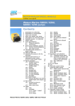
Appendix A: Watson Marlow 620RE4/R Pump Head Manual
~ 33 ~
620R-gb/2
620R
620RE, 620RE4 & 620R Key safety information
Before opening the pumphead guard please ensure that the following safety directions are
followed.
•
For close coupled drives, ensure that the pump is isolated from mains voltage.
•
Ensure that there is no pressure in the pipeline.
•
If a tube failure has occurred, ensure that any product in the pumphead has been allowed to drain through the controlled waste
to a suitable drain.
•
Ensure that protective clothing and eye protection is worn if hazardous products are being pumped.
620RE, 620RE4 & 620R Safe-guarding
•
Primary safety on 620 series pumps is provided by the tool-lockable pumphead guard. On electrically-powered cased 600
series pumps, secondary (backup) protection is provided in the form of an electrical interlock which stops the pump if the
pumphead guard is opened (and only for so long as the guard is opened). The electrical interlock on cased pumps should
never be used as primary protection. Always disconnect the mains power supply to the pump before opening the pumphead
guard.
•
Only primary protection through the tool-lockable guard is provided on pneumatically powered 620 series cased pumps. Only
primary protection through the tool lockable pumphead guard is provided on 620 series pumps fitted with industrial AC motors,
but an interface kit to allow mains power to be switched by the pumphead guard interlock is available as an extra-cost option.
620RE, 620RE4 & 620R Pumping conditions
Pressure and viscosity
•
All pressure values in this operating instruction, from which performance and life figures have been calculated relate to peak
pipeline pressures.
•
Although rated to 4 bar working pressure, this pump will generate in excess of 4 bar working pressure if pipeline restrictions
are in place. In instances where it is critical that a working pressure of 4 bar is not exceeded, pressure relief valves should be
installed in the pipeline.
•
For pumping duties of 2-4 bar pressure, only close coupled pumps should be used, fitted with 73 Shore hardness Marprene/
Bioprene or standard STA-PURE tube elements. “M” in the tube element’s product order code denotes suitability for high
pressure use.
•
When pumping duties of 0-2 bar pressure, use close coupled or cased pumps fitted with 64 Shore hardness elements or the
standard range of continuous peristaltic pump tubing.
•
Viscosity handling is maximised by using 73 Shore hardness Marprene/Bioprene or STA-PURE tube elements in the pumphead.
•
Ensure that there is always a minimum of one metre of smooth bore flexible tubing connected to the discharge port of the
pumphead. This will help minimise any impulse losses and pulsation in the pipeline. This is especially important with viscous
fluids and rigid pipework.
620RE, 620RE4 & 620R Pump installation
A correctly engineered installation will promote the best possible tube life, so please ensure that the following guidelines are
followed:
•
Avoid tight pipeline bends, pipe reducers and excessive lengths of smaller bore tubing than that in the pumphead, particularly
in pipelines on the suction side.
•
Ensure that connecting pipe work and fittings are suitably rated to handle the predicted pipeline pressure.
•
If rigid pipe work comes in close proximity to the pumphead, a drop out section of pipe work will simplify tube replacement.
•
Ensure that the controlled waste blanking plug is in position in the controlled waste port not in use. See below.
2
•
It is advisable to use controlled waste pipe work if pumping hazardous, aggressive or abrasive fluids or products which will
harden in contact with air.
•
When connecting waste pipe work to the controlled waste port using the coupling adaptor supplied, ensure that there is
adequate clearance underneath the pumphead. Waste pipe work should run to a suitable container or drain.
•
The leak detector installation procedure is included in the leak detector kit.
•
If unsure of an installation please contact your local Watson-Marlow Technical Support Office for further assistance.
620RE, 620RE4 & 620R General operation
Opening the pumphead guard
•
Unlock the guard with a 5mm Allen key or a screw driver.
•
Open the guard to its full extent. This creates the maximum clearance between the tube ports and guard to remove the tubing.
Engaging/disengaging the rollers
•
The extent of travel of the roller release levers is indicated below. Do not try and force the levers beyond their normal extent of
travel as this will damage the rotor.
•
To engage the rollers snap the roller release levers counter clockwise making sure that the rollers locked out against the
tubing. To disengage the rollers, snap the release levers clockwise to their disengaged position. For high pressure tubing
elements or four roller pumpheads, the 5mm Allen key can be used to aid leverage when engaging/disengaging the rollers
with the release levers.
Make sure that fingers are clear of the front face of the rotor hub when using the roller release
levers.
Pre-load checks
•
Before loading tubing, ensure that all rollers rotate freely, that the tube ports and location grooves are clean and that if in use,
the controlled waste pipe work is free of any obstructions.
Closing the pumphead guard and start-up
•
Ensure that the guard seal is clean, replacing it if necessary.
•
Ensure that the rollers are engaged and locked out against the tubing.
•
Close the guard and push it against the track until the latch engages.
•
Connect suitable pipe work to the pumphead using the appropriate connectors for the tube element.
Continuous tubing clamp location in 620R pumpheads
•
Select the appropriate tube clamp set for the tubing size to be used.
•
Locate the two “U” shaped track clamp halves into the pumphead ports (The “U” shape ensures correct loading).
•
Locate the corresponding guard clamp halves which have raised “T” locating sections, into the slots on the inner guard face
above and below the guard hinge. Push and slide into their locked position.
•
Closing the guard will align the two halves of the clamp around the tubing.
3
620RE & 620RE4 tube element loading
•
620RE element pumpheads are factory set to accept Watson-Marlow LoadSure tube elements. Pumping performance will be
adversely affected if LoadSure elements are not used.
•
Disengage rollers.
•
Locate one of the “D” shaped flanges into the lower port. (The “D” flange ensures that the element can only be loaded correctly).
•
Wrap the tube element around the disengaged rollers of the rotor.
•
Locate the second “D” shaped flange into the upper port.
•
Ensure the flat face of each “D” flange sits flush to the flange sealing face of the track.
•
Engage rollers.
•
Close the guard and push it against the track until the latch engages.
Tube element loading
620RE, 620RE4 & 620R Continuous tube loading
•
620R continuous tubing pumpheads are factory set to accept Watson-Marlow 600 series 3.2mm wall tubing. Pumping
performance will be adversely affected if Watson-Marlow tubing is not used.
•
Select the tube clamp set which is correct for the tubing size to be used.
•
Disengage rollers.
•
Locate one end of the tubing into the lower port “U” clamp and hold firmly in position.
•
Wrap the tubing tightly around the retracted rollers, making sure that there is no twisting through its length.
•
Locate the other end of the tubing into the upper port “U” clamp.
•
Hold both ends of the tubing in one hand maintaining tension around the retracted rollers.
•
Engage rollers.
•
Close the guard and push it against the track until the latch engages.
•
Ensure that continuous tubing is not loosely clamped at the pumphead ports.
•
Ensure that when the pump is re-started all of the rollers have re-engaged. A roller which has not re-engaged will “click”
continuously. No damage will occur if this happens but the roller should be re-engaged manually using the 5mm Allen key.
Please refer to the Troubleshooting section.
4
Continuous tube loading
620RE, 620RE4 & 620R Tube element or continuous tube removal
•
•
•
Unlock the guard and disengage the rollers.
Disconnect the tubing from the external pipeline.
Remove the tubing from the pumphead.
5
620RE, 620RE4 & 620R Maintenance
Scheduled maintenance
•
The stainless steel pumping rollers run on sealed bearings and do not require lubrication.
•
Remove the rotor and lubricate the follower rollers and roller engaging mechanisms with a molybdenum based grease. This
should be carried out every six months for intermittent duties and every three months for 24 hour duties.
•
If fluid is spilled inside the pumphead, flush the pumphead out with water and mild detergent as soon as possible. If specific
cleaning agents are required to clean the spillage, please consult Watson-Marlow Technical Support Office before proceeding,
in order to confirm chemical compatibility.
•
If the rotor needs to be removed, refer to the guidelines below.
Rotor removal and re-location
•
Remove the rotor cover and central locating bolt using a 5mm Allen key. Pull the rotor off the keyed shaft, remove the plastic key
and clean thoroughly. Do not use tools to lever the rear face of the rotor away from the inner face of the track, it should come off
by hand.
•
To replace the rotor, locate the key into the keyway and apply a thin layer of molybdenum grease over the shaft and key. Align the
keyway of the rotor to the shaft key and slide the rotor into position, ensuring that a positive “stop” is achieved and ensure that
the full length of the drive shaft is fitted into the rotor.
There is only one parallel keyway in the rotor hub which is clearly marked with a hole at one
end. If one of the remaining three unmarked slots is used as a keyway, it is likely that the rotor
hub will sustain irrevocable damage.
•
•
Do not force the rotor into position. The rotor will slide into place easily if correctly aligned.
Tighten the hexagonal locating bolt to a nominal torque of 10Nm using a 5mm Allen key. Replace the rotor cover.
When closing the guard, check it does not make contact with the rotor. If it does, then the rotor has been fitted incorrectly. Re-open
the guard, remove and refit the rotor, and close the guard.
6
Track removal (close coupled AC motor gearboxes)
•
Remove the rotor.
•
Disconnect the controlled waste pipework if attached.
•
Loosen the four track retaining screws using a “Number 2 Posi-Drive” screwdriver.
•
Disconnect the mains interlock if connected to a mains contactor.
•
Withdraw the track fully from the gearbox.
Track re-location (close coupled AC motor gearboxes)
•
Ensure that the track is clean.
•
Fit the track over the gearbox boss.
•
Align the track horizontally so that the location holes are aligned with the threaded gearbox holes.
•
Tighten the four track retaining screws using a “Number 2 Posi-Drive” screwdriver.
•
Re-connect the guard interlock controlled waste pipework if required.
620RE, 620RE4 & 620R CIP & SIP
General
•
Unlock the guard and disengage the rollers within the tube zone.
•
Close the guard and squeeze against the track until the latch clicks.
•
Observe a 1m safety area.
CIP
•
LoadSure tube elements and continuous tubing can be cleaned using CIP processes.
•
Ensure that the tubing material is chemically compatible with the cleaning agent that is to be used.
•
If cleaning agents are spilled over the pumphead, wash down immediately.
•
Ensure that controlled waste pipework is fitted to allow a safe release of cleaning agent in the event of a tube failure.
7
SIP
•
Only STA-PURE tube elements can be used in a steam in place sterilisation processes.
•
STA-PURE tubing elements can be sterilised to 3A Class two and FDA minimum recommended standard which is 121C
(250F) at 1 bar (14.5 psi) saturated steam for 30 minutes.
•
Monitor the process continuously.
•
If a tube failure occurs, shut down the process. Do not touch the pumphead until a 20 minute cooling period has been
observed.
•
Ensure a 20 minute acclimatisation period is observed before running the pump following SIP.
•
Ensure that controlled waste pipework is fitted to allow a safe release of steam in the event of a tube failure.
•
Ensure a 1m safety zone is maintained around the pumphead during SIP cycles.
Ensure that the pumphead door is closed and locked before SIP cleaning commences.
8
Pumphead spares
16
17
15
14 13
18
12
1
11
2
10 9
8
7
6
5
3
4
Number
Spare
Description
1
MRA0249A
Stainless steel roller for 4mm wall
MRA0250A
Stainless steel roller for 3.2mm wall
2
MR2012T
Stainless steel roller spindle
3
CX0148
Stainless steel cir-clip
4
TT0006
5mm Allen key
5
MR2032T
Key
6
MR2055M
Rotor cover
7
FN0581
Washer M6
8
MR2027T, MR2096T
Controlled waste port pipe work connector
9
FN0503
Rotor locating bolt
10
MR 2029T
Rotor spacer (cased drives only)
11
MRA0252A
Rotor assembly 2 roller element
MRA0253A
Rotor assembly 4 roller element
MRA0254A
Rotor assembly 2 roller continuous
MRA0255A
Rotor assembly 4 roller continuous
12
MR2007M
Release lever
13
MR2052C
Latch clip
14
MR2053B
Latch bolt
15
MRA0251A
Track assembly
16
MR2018T
Hinge pin
17
MR2002M
Guard
18
MR2028M
Controlled waste port blanking plug
SW0159
Interlock
FN0523
Close coupled track locating screws
FN0488
Cased drive track locating screws
9
Product use and decontamination declaration
In compliance with the UK Health & Safety at Work Act and the Control of Substances Hazardous to Health
Regulations you, the user are required to declare the substances which have been in contact with the product(s)
you are returning to Watson-Marlow or any of its subsidiaries or distributors. Failure to do so will cause delays in
servicing the product. Therefore, please complete this form to ensure that we have the information before
receipt of the product(s) being returned. A FURTHER COPY MUST BE ATTACHED TO THE OUTSIDE OF THE
PACKAGING CONTAINING THE PRODUCT(S). You, the user, are responsible for cleaning and decontaminating the product(s) before returning them.
Please complete a separate Decontamination Certificate for each pump returned.
RGA No: ......................
1
Company
Address
........................................
Postcode ........................................
Telephone
........................................
Fax Number ...................................
3.4 Cleaning fluid to be used if residue of chemical is found during
servicing;
2 Product
2.1 Serial Number ................................
(a) ..............................................................
2.2 Has the Product been used?
YES
(b) ……………………………………………
(c) ……………………………………………
NO
(d) ……………………………………………
If yes, please complete all the following
Sections
If no, please complete Section
5 only
3 Details of substances pumped
3.1 Chemical names:
4 I hereby confirm that the only substances(s) that the equipment
specified has pumped or come into contact with are those named, that the
information given is correct, and the carrier has been informed if the
consignment is of a hazardous nature.
(a) .......................................................
5 Signed ……………………………………………….. ......
(b) .......................................................
Name …………………………………………………
(c) .......................................................
Position ……………………………………………….
(d) .......................................................
Date …………………………………………………..
3.2 Precautions to be taken in
handling these substances:
(a) ........................................................
(b) ....................................................................................................... Note: To assist us in our servicing
please describe any fault condition
(c) ........................................................
you have witnessed.
(d) ........................................................
3.3 Action to be taken in the event of human contact:
(a) ………………………………………………………………….
(b) ………………………………………………………………….
(c) ………….………………………………………………………
(d) ………….………………………………………………………
Watson-Marlow Limited Falmouth Cornwall TR11 4RU England Tel: 01326 370370 Fax: 01326 376009
10
Standard Helical Inline Gearboxes
BIM 1012
Installation and Maintenance Instructions
USA
Retain These Safety Instructions For Future Use
CDN
INSPECTION OF UNIT
Thoroughly inspect the equipment for any shipping and handling damage before accepting shipment from the freight company. If any of the
goods called for in the bill of lading or express receipt are damaged or the quantity is short, do not accept until the freight or express agent
makes an appropriate notation on your freight bill or express receipt. If any concealed loss or damage is discovered later, notify your freight
carrier or express agent at once and request him to make an inspection. We will be very happy to assist you in collecting claims for loss or
damage during shipment; however, this willingness on our part does not remove the transportation company’s responsibility in reimbursing
you for collection of claims or replacement of material. Claims for loss or damage in shipment must not be deducted from the NORD Gear
invoice, nor should payment of the NORD Gear invoice be withheld awaiting adjustment of such claims, as the carrier guarantees safe
delivery.
If considerable damage has been incurred and the situation is urgent, contact the nearest NORD Gear Sales Office for assistance. Please
keep a written record of all communications.
RECORD NAMEPLATE DATA
Locate the gear reducer nameplate and record all nameplate data for future reference.
SK ________________________________________________________ S/N _________________________________
RATIO ______________ MAX TORQUE ____________________ RPM ______________ MTG. POS ______________
STORAGE
PROPER STORAGE UNTIL INSTALLED
Keep unit in a dry, temperature controlled area. If stored other
than said, long term storage methods must be applied to the unit
including complete fill with lubricant. Protect machined surfaces
and rotate shafts periodically. Prior to putting unit into service,
drain lubricant and refill to proper level as determined by the
mounting position.
BIM 1012/2005/03
PROPER HANDLING OF THE UNIT
Exercise care to prevent damage to the unit when moving. Lift
onIy at designed Iifting points. Do not attach other machinery and
lift by the unit lifting points. The lifting points are to be used to lift
the unit only. Insure that adequate safety measures are taken to
protect personneI during transportation. Protect the mounting
surface from damage.
Page 1 of 10
www.nord.com
INSTALLATION OF UNIT
To ensure Iong service and dependabIe performance, an encIosed gear drive must be rigidIy supported and the shafts accurateIy aIigned.
The foIIowing describes the minimum precautions required to accompIish this end.
FOUNDATION
The responsibiIity for the design and construction of the
foundation Iies with the user. The foundation must be adequate
to withstand normaI operating Ioads and possibIe overIoads whiIe
maintaining aIignment to attached system components under
such Ioads.
MOUNTING POSITION
UnIess a unit is specificaIIy ordered for incIined mounting, the
foundation must be IeveI and fIat. The Iubrication system may
not operate properIy if the unit is not mounted in the position for
which it is designed. It may be desirabIe to eIevate the
foundation to faciIitate oiI drainage.
CONCRETE FOUNDATION
If a concrete foundation is used, steeI mounting pads and boIts of
sufficient size to distribute the stress into the concrete shouId be
grouted into the foundation.
STEEL FOUNDATION
If a structuraI steeI foundation is used (i.e. wide fIange beams or
channeIs), a base pIate or soIe pIate of suitabIe thickness shouId
be used and shouId extend under the entire unit.
FOOT MOUNTED UNITS
Use shims under the feet of the unit to align the output shaft to the
driven equipment. Make sure that all feet are supported so that
the housing will not distort when it is bolted down. Improper
shimming will reduce the life of the unit and may cause failure.
Dowel pins may be installed to prevent misalignment and ensure
proper realignment if removed for service.
FLANGE MOUNTED UNITS
If a structuraI steeI foundation is used (i.e. wide fIange beams or
channeIs), a base pIate or soIe pIate of suitabIe thickness shouId
be used and shouId extend under the entire unit. If a buIk head
pIate is used it shouId be of proper strength to minimize buckIing
distortions.
FIange PiIot ‘AK’ or ‘AK1’ toIerance
Metric (mm)
> ∅ 50 ≤ ∅ 80 = +0.012/-0.007
> ∅ 80 ≤ ∅ 120 = +0.013/-0.009
> ∅ 120 ≤ ∅ 180 = +0.014/-0.011
> ∅ 180 ≤ ∅ 230 = +0.016/-0.013
> ∅ 230 ≤ ∅ 315 = +0.000-0.032
> ∅ 315 ≤ ∅ 400 = +0.000/-0.036
> ∅ 400 ≤ ∅ 500 = +0.000/-0.040
FITS
CIearance or interference fits for coupIing hubs shouId be in
accordance with ANSI/AGMA 9002-A86 or as follows.
Output and Input shaft Diameter toIerance
Metric (mm)
≤ ∅ 18 = +0.012/+0.001
> ∅ 18 ≤ ∅ 30 = +0.015/+0.002
> ∅ 30 ≤ ∅ 50 = +0.018/+0.002
> ∅ 50 ≤ ∅ 80 = +0.030/+0.011
> ∅ 80 ≤ ∅ 120 = +0.035/+0.013
> ∅ 120 ≤ ∅ 180 = +0.040/+0.015
Inch
≤ ∅ 1.750 = +0.0000/-0.0005
> ∅ 1.750 = +0.0000/-0.0010
Output and Input shaft DriII and tap shaft end
Metric (mm)
≤ ∅ 16 = M5
> ∅ 16 ≤ ∅ 21 = M6
> ∅ 21 ≤ ∅ 24 = M8
> ∅ 24 ≤ ∅ 30 = M10
> ∅ 30 ≤ ∅ 38 = M12
> ∅ 38 ≤ ∅ 50 = M16
> ∅ 50 ≤ ∅ 85 = M20
> ∅ 85 ≤ ∅ 130 = M24
Inch
≤ ∅ 0.438 = #10-24 x 0.4 deep
> ∅ 0.438 ≤ ∅ 0.813 = ¼-20 x 0.6 deep
> ∅ 0.813 ≤ ∅ 0.938 = 5/16-18 x 0.7 deep
> ∅ 0.938 ≤ ∅ 1.125 = 3/8-16 x 0.9 deep
> ∅ 1.125 ≤ ∅ 1.375 = 1/2-13 x 1.1 deep
> ∅ 1.375 ≤ ∅ 1.875 = 5/8-11 x 1.4 deep
> ∅ 1.875 ≤ ∅ 3.250 = 3/4-10 x 1.7 deep
> ∅ 3.250
= 1-8 x 2.2 deep
Outboard pinion and sprocket fits shouId be as recommended by
the pin sprockets with interference fits shouId be heated
according to the manufacturer’s recommendations, generaIIy
250°F to 300°F, (120°C to 150° C) before assembIing to the shaft.
Inch
> ∅ 1.969 ≤ ∅ 3.150 = +0.005/-0.0003
> ∅ 3.150 ≤ ∅ 4.724 = +0.005/-0.0004
> ∅ 4.724 ≤ ∅ 7.087 = +0.006/-0.0004
> ∅ 7.087 ≤ ∅ 9.055 = +0.006/-0.0005
> ∅ 9.055 ≤ ∅ 12.402 = +0.000/-0.0013
> ∅ 12.402 ≤ ∅ 15.748 = +0.000/-0.0014
> ∅ 15.748 ≤ ∅ 19.685 = +0.000/-0.0016
BOLT STRENGTH
BoIt size, strength and quantity shouId be verified to insure proper
torque reaction capacity whatever the mounting arrangement.
PRIME MOVER MOUNTING
AIign the prime mover to the reducer-input shaft using shims
under the feet. Make sure that the feet are supported. DoweI the
prime mover to its foundation.
SHAFT CONNECTIONS
When connecting shafts to either the input or output of the
reducer, consider the foIIowing instructions.
BIM 1012/2005/03
Page 2 of 10
www.nord.com
LOCATION
CoupIing hubs shouId be mounted fIush with the shaft ends,
unIess specificaIIy ordered for overhung mounting. Pinions,
sprockets and sheaves shouId be mounted as cIose as possibIe
to the unit housing to minimize bearing Ioads and shaft
defIections.
COUPLING ALIGNMENT
Shaft coupIings shouId be instaIIed according to the coupIing
manufacturer’s recommendations for gap, anguIar and paraIIeI
aIignment. In many instaIIations, it is necessary to aIIow for
thermaI and mechanicaI shaft movement when determining shaft
aIignment. The coupIing manufacturer’s recommendations
shouId be foIIowed.
5.
CHANGES IN PERFORMANCE SPECIFICATIONS
Owner has the responsibiIity to consult with NORD GEAR if such
items such as applied Ioads, operating speeds or other operating
conditions have changed.
WARNING:
LOCK OUT POWER before any maintenance is performed.
Make absolutely sure that no voltage is applied while work is
being done on the gearbox.
AXIAL DISPLACEMENT
The gap between shaft ends shouId be the same as the specified
coupIing gap unIess overhung mounting of the coupIing hub is
specified. The coupIing gap and shaft gap must be sufficient to
accommodate any anticipated thermaI or mechanicaI axiaI
movement.
ANGULAR ALIGNMENT
Insert a spacer or shim stock equaI to the required coupIing gap
between the coupIing hub faces and measure the cIearance using
feeIer gauges. Repeat this at the same depth at 90-degree
intervaIs to determine the amount of anguIar misaIignment.
PARALLEL ALIGNMENT
Mount a diaI indicator to one coupIing hub, and rotate this hub,
sweeping the outside diameter of the other hub. The paraIIeI
misaIignment is equaI to one-haIf of the totaI indicator reading.
Another method is to rest a straight edge squareIy on the outside
diameter of the hubs at 90-degree intervaIs and measure any
gaps with feeIer gauges. The maximum gap measurement is the
paraIIeI misaIignment.
CHECKING ALIGNMENT
After both anguIar and paraIIeI aIignments are within specified
Iimits, tighten aII foundation boIts secureIy and repeat the above
procedure to check aIignment. If any of the specified Iimits for
aIignment are exceeded, reaIign the coupIing.
SPROCKET OR SHEAVE ALIGNMENT
AIign the sheaves or sprockets square and paraIIeI by pIacing a
straight edge across their faces. AIignment of bushed sheaves
and sprockets shouId be checked after bushings have been
tightened. Check horizontaI shaft aIignment by pIacing a IeveI
verticaIIy against the face of the sheave or sprocket. Adjust beIt
or chain tension per the manufacturer’s specified procedure.
Ensure that driving equipment is running in the correct
direction before coupling to reducers with backstops
(designed to operate onIy in a specific direction) or
machinery designed to operate only in one direction.
START-UP
1.
2.
Ensure that switches, aIarms, heaters, coolers and other
safety and protection devices are instaIIed and operational
for their intended purpose.
Verify that the installed mounting position is the same as the
nametag mounting position. If not, adjust the oil level
accordingly and relocate the vent plug, fill plug and drain
plug according to the mounting position. See following.
AUTOVENT PLUG
The Autovent plug is brass in color and will be located at the
highest point on the gearbox. It operates like a check-valve to
allow the reducer to relieve internal pressure while preventing
lubricant contamination during cooling. A spring presses a ball or
plunger against a machined orifice until pressure exceeds 2 psi.
Above 2 psi the air is allowed to escape depressurizing the
gearcase. When internal pressure drops below 2 psi, the
autovent re-seals closing the unit to the outside environment.
After shutdown, the reducer cools along with the air inside the
reducer. The unit will temporarily maintain a slight vacuum until
normalization occurs. NORD Gear supplies an Autovent as a
standard feature.
OUTBOARD PINION ALIGNMENT
AIign the pinion by adjusting the gear tooth cIearance according
to the manufacturer’s recommendations and checking for
acceptabIe outboard pinion tooth contact. The foundation boIts
may have to be Ioosened and the unit moved sIightIy to obtain
this contact. When the unit is moved to correct tooth contact, the
prime mover shouId be reaIigned.
RECHECK ALIGNMENT
After a period of operation, recheck aIignment and adjust as
required.
1.
2.
3.
4.
The Autovent releases built-up air pressure from
inside the gearbox (Max. pressure 2 psi).
Properly install unit on a rigid foundation
•
adequateIy supported
•
secureIy boIted into pIace
•
IeveIed so as not to distort the gear case
Properly install couplings suitabIe for the application and
connected equipment.
Ensure accurate aIignment with other equipment.
Furnish and install adequate machinery guards as needed to
protect operating personneI and as required by the
appIicabIe standards of the OccupationaI Safety and HeaIth
Administration (OSHA), and by other appIicabIe safety
reguIations;
BIM 1012/2005/03
Page 3 of 10
www.nord.com
LUBRICANT
AII NORD reducers are shipped from the factory properIy fiIIed
with Iubricant and all plugs are installed according to the mounting
position given on the reducer nametag. Acceptable oil fill level is
within ½ inch of the bottom of the fill plug threads.
FILL LEVEL & DRAIN PLUGS
The drain plugs are metric socket head cap screws. They will be
located at the lowest part of the gearbox for ease of draining. The
fill level plug is a hex head cap screw. It will be located between
the Autovent and drain plug. Both types of plugs will have gaskets
included to prevent oil from leaking.
OPERATION AND MAINTENANCE CHECKLIST
1. Operate the equipment as it was intended to be operated
2. Do not overIoad.
3. Run at correct speed.
4. Maintain Iubricant in good condition and at proper IeveI.
5. Dispose of used Iubricant in accordance with appIicabIe
Iaws and reguIations.
6. AppIy proper maintenance to attached equipment at
prescribed intervaIs recommended by the manufacturer.
7. Perform periodic maintenance of the gear drive as
recommended by NORD.
Two types of plugs for maintenance
MAINTENANCE
Mineral lubricant should be changed every 10,000 service hours or after two years. For synthetic oils, the lube should be changed every
20,000 service hours or after four years. In case of extreme operating (e.g. high humidity, aggressive environment or large temperature
variations), shorter intervals between changes are recommended.
OIL SPECIFICATIONS
NORD supplies aII reducers fiIIed with oiI from the factory. Consult the sticker adjacent to the fill plug to determine the type of lubricant
installed at the factory. Standard lubricant is ISO VG220 mineral-based oil. However, some units have special lubricants designed to operate
in certain environments or to extend the service life of the lubricant. If in doubt about which lubricant is needed, contact NORD Gear.
STANDARD OIL – ISO VG220
Ambient Temperature
20 to 104°F (-5 to 40°C)
FormuIation
MineraI
TYPICAL OILS
Viscosity
ISO NLGI
Formulation
Service
Temperature
Range
Conventional 20°C to +50°C
Mineral
68F to +122°F
VG 460
Synthetic
-30°C to +80°C
PAO
-22°F to +176°F
Conventional
0°C to +30°C
Mineral
32°F to +86°F
VG 320
Synthetic
-35°C to +80°C
PAO
-31°F to +176°F
Conventional
-5°C to +40°C
Mineral
+20°F to +104°F
VG 220
Synthetic
-34°C to +80°C
PAO
-30°F to +176°F
Conventional -15°C to +25°C
VG 150
Mineral
5°F to +77°F
&
Synthetic
-37°C to +10°C
VG 100
PAO
-35°F to +50°F
Conventional -15°C to +25°C
Mineral
5°F to +77F
VG 68
Synthetic
-40°C to +10°C
PAO
-40°F to +50F
Synthetic
-40°C to +10°C
VG 32
PAO
-40°F to +50°F
PAO = Poly Alpha Olefin
BIM 1012/2005/03
Shell
Mobilgear
634
Mobil
SHC 634
Mobilgear
632
Mobil
SHC 632
Mobilgear
630
Mobil
SHC 630
Mobilgear
629
Mobil
SHC 629
Mobilgear
626
Mobil
SHC 626
Mobil
SHC 624
Omala
460
Omala
460 HD
Omala
320
Omala
320 HD
Omala
220
Omala
220 HD
Omala
100
Omala
150 HD
Omala
68
Castrol
7EP
Isolube
EP 460
6EP
Isolube
EP 460
5EP
Isolube
EP 220
4EP
Isolube
EP 150
2EP
Klüberoil
GEM 1-460
Klübersynth
EG 4-460
Klüberoil
GEM 1-320
Klübersynth
EG 4-320
Klüberoil
GEM 1-220
Klübersynth
EG 4-220
Klüberoil
GEM 1-150
Klübersynth
EG 4-150
Klüberoil
GEM 1-68
Energol
Tribol
GR-XP 460 1100/460
Tribol
N/A
1510/460
Energol
Tribol
GR-XP 320 1100/320
Tribol
N/A
1510/320
Energol
Tribol
GR-XP 220 1100/220
Tribol
N/A
1510/220
Energol
Tribol
GR-XP 100 1100/100
N/A
N/A
Energol
GR-XP 68
Tribol
1100/68
N/A
Isolube
EP 68
N/A
N/A
N/A
N/A
N/A
Klüber-Summit
HySyn FG-32
N/A
N/A
Page 4 of 10
www.nord.com
SPECIAL PURPOSE LUBRICANTS
Ambient Temperature
20 to 104°F (-5 to 40°C)
20 to 104°F (-5 to 40°C)
5 to 125°F (-20 to 50°C)
-30 to 140°F (-35 to 60°C)
-30 to 140°F (-35 to 60°C)
FormuIation
Food Grade Oil - Synthetic
Food Grade Oil - Synthetic
FIuid Grease
FIuid Grease - Synthetic
FIuid Grease - Synthetic
Manufacturer
Chevron
OilJAX
MobiI
MobiI
SheII
Oil Brand Name
FM ISO 220
MagnapIate 85W140-FG
MobiIux EP023
MobiIith SHC 007
Albida LC
Manufacturer
SheII
LubripIate
Grease Brand Name
AerosheII 6
SFL1
STANDARD BEARING GREASE – NLGI 2EP Lithium
Ambient Temperature
-20 to 140°F (-30 to 60°C)
FormuIation
MineraI
OPTIONAL BEARING GREASES
Ambient Temperature
-40 to 230°F (-40 to 110°C)
-40 to 230°F (-40 to 110°C)
FormuIation
Synthetic
Food Grade - Synthetic
MOUNTING POSITIONS
These charts detail the mounting positions for horizontal and vertical mounting. For mounting orientations other than shown consult NORD
Gear.
B3
B3 / B5
B5
V1
V3
V1 / V5
B5b
B8 / B5
B5a
B5c
V5
B8
BIM 1012/2005/03
B6
V6
V3 / V6
B7
Page 5 of 10
www.nord.com
LUBRICANT CAPACITY
Each reducer has the oil level and oil quantity adjusted according to the mounting position shown in the tables. When replacing the oil, consult
the tables below to determine the proper amount of oil to be installed according to the reducer size and mounting position. Note that this is
approximate and the final level will be adjusted when the reducer is installed. Acceptable oil fill level is within ½ inch of the bottom of the fill
plug threads.
LUBRICATION CAPACITY – STANDARD LINE
Horizontal position
Vertical position
Horizontal position
Vertical position
Mounting position
double reduction
triple reduction
B3, B5, B5a, B8, B6, B7
V1, V3, V5, V6
B3, B5, B5a, B8, B6, B7
V1, V3, V5, V6
quarts
0.11
0.16
SK 0
liters
0.10
0.15
quarts
0.26
0.42
quarts
0.63
0.69
SK 01
SK 010
liters
0.25
0.40
liters
0.60
0.65
quarts
0.54
0.74
quarts
1.37
1.48
SK 20
SK 200
liters
0.51
0.70
liters
1.30
1.40
quarts
0.74
1.06
quarts
1.48
1.58
SK 25
SK 250
liters
0.70
1.00
liters
1.40
1.50
quarts
0.85
1.48
quarts
1.48
1.58
SK 30
SK 300
liters
0.80
1.40
liters
1.40
1.50
quarts
1.06
1.69
quarts
1.58
1.67
SK 33
SK 330
liters
1.00
1.60
liters
1.50
1.58
Note: Filling quantities are approximate figures. Oil level must be checked according to oil level plug after final installation.
Acceptable oil fill level is within ½ inch of the bottom of the fill plug threads For mounting angles not shown, consult factory.
The mounting position of the gearbox dictates the location of the Autovent. Below is a table and illustrations to show where the Autovent
should be located per the specified mounting position. The Autovent must be at the highest location of the gearbox.
Mounting
Position
Autovent
Location
B3, B5, B3/B5
1
B8, B5a, B8/B5a
4
B6
3
B7
5
V3, V6, V3/V6
4
V1, V5, V1/V5
2
BIM 1012/2005/03
Page 6 of 10
www.nord.com
PARTS LIST
I
II
RECOMMENDED SPARE PARTS
Bearings – all
Gaskets – all
Shims – all
Seals – all
Seal Plugs – all
IMPORTANT!
When ordering parts, it is necessary to have the NORD SERIAL NUMBER from the unit
the parts are for. The serial number will dictate the correct parts for that particular unit.
The gearbox nameplate will have the serial number on it.
BIM 1012/2005/03
Page 7 of 10
1
2
3
5
5a
6
7
8
9
10
11
12
14
15
16
17
18
19
20
21
22
23
24
25
26
27
30
31
32
52
53
54
55
56
57
58
59
60
61
62
63
64
65
66
68
69
70
71
74
Output shaft
Key
Shaft seal
Output shaft bearing, normal
Output shaft bearing, reinforced
Output shaft bearing
Seal
Vent screw
Shim
Driven gear
Key
Circlip
Driving pinion
Gear case
Pinion shaft bearing
Driven pinion
Key
Driving gear
Seal
Plug
Gear case cover
Pinion shaft bearing
Shim
Hexagon bolt
Washer
Spiral pin
Seal
Shim
Seal
Spiral pin
Spiral pin
Intermediate shaft, gearcut
Hexagon bolt
Washer
Seal
Seal
Plug
Intermediate shaft, plain
Grooved ball bearing
Grooved ball bearing
Key
Shim
Driving gear
Driving pinion
Gear case 3rd.-red.
Gear case cover
Hexagon bolt
Washer
Seal
900
901
902
904
905
906
907
908
909
910
911
914
916
918
924
925
929
932
938
939
940
941
942
943
947
948
949
950
Rotor with shaft, plain
Rotor with shaft, gearcut
End shield A
Shaft seal
Bearing A
Bearing shim
Terminal box frame
Terminal box cover
Terminal box frame gasket
Terminal box cover gasket
Terminal board
cable entry gland
Stator case
Key
Collar bolt
Hexagonal nut
Bearing B
End shield B
Second motor shaft end
Fan
Fan cover
Key
Circlip
Key
Circlip
Circlip
Oval flat-head bolt
Oval flat-head bolt
www.nord.com
PARTS LIST
BIM 1012/2005/03
Page 8 of 10
34
35
38
40
41
42
42a
43
44
45
46
47
48
49
Socket head bolt
Shim
Key
Input bearing housing
Grooved ball bearing
Grooved ball bearing, normal
Grooved ball bearing, reinforced
Shaft seal
Key
Circlip
Circlip
Circlip
Input shaft gearcut
Input shaft, plain
80
Input shaft
81
83
85
86
87
88
90
92
95
103
106
Circlip
Circlip
IEC Adaptor
Input shaft bearing
Shaft seal
Input shaft gearcut
Clutch pinion shaft
Shim
Oil flinger
Coupling
Set screw
www.nord.com
NOTES
BIM 1012/2005/03
Page 9 of 10
www.nord.com
TROUBLE SHOOTING
PROBLEM WITH THE REDUCER
Overloading
POSSIBLE CAUSES
Load exceeds the capacity of the
reducer
Insufficient lubrication
Runs Hot
Improper lubrication
Excessive lubrication
Wrong lubrication
Loose foundation bolts
Runs Noisy
Worn RV Disc
Failure of Bearings
Insufficient Lubricant
Output Shaft
Does Not Turn
Internal parts are broken
Weak mounting structure
Loose hold down bolts
Overloading unit may result in
damage to disc
May be due to lack of lubricant
Overload
Level of lubricant in the reducer not
properly maintained.
Overloading of reducer can cause
damage.
Key missing or sheared off on input
shaft.
Coupling loose or disconnected.
Worn Seals
Caused by dirt or grit entering seal.
Overfilled reducer.
Oil Leakage
Autovent clogged.
Improper mounting position, such as
wall or ceiling mount of horizontal
reducer.
BIM 1012/2005/03
Page 10 of 10
SUGGESTED REMEDY
Check rated capacity of reducer, replace
with unit of sufficient capacity or reduce
load
Check lubricant level and adjust up to
recommended levels
Check lubricant level and adjust down to
recommended levels
Flush out and refill with correct lubricant as
recommended
Inspect mounting of reducer. Tighten loose
bolts and/ or reinforce mounting and
structure
Tighten bolts
Disassemble and replace disc. Recheck
rated capacity of reducer.
Replace bearing. Clean and flush reducer
and fill with recommended lubricant.
Check rated capacity of reducer.
Check lubricant level and adjust to factory
recommended level.
Replace broken parts. Check rated capacity
of reducer.
Replace key.
Properly align reducer and coupling.
Tighten coupling.
Replace seals. Autovent may be clogged.
Replace or clean.
Check lubricant level and adjust to
recommended level.
Clean or replace, being sure to prevent any
dirt from falling into the reducer.
Check mounting position. Name tag & verify
with mounting chart in manual.
www.nord.com
Appendix B: Levitronix Puralev® 200 SU Manual
~ 34 ~
®
Levitronix Bearingless Pumps
www.levitronix.com
BPS-200
2.6 bar
21 liters/min
(37.7 psi)
(5.5 gallons/min)
USER MANUAL
This manual contains information necessary for the safe and proper use of the BPS-200.
Included are specifications for the standard configurations of the pump system and
instructions regarding its use, installation, operation, adjustment, inspection and maintenance. For special configurations of the pump system refer to accompanying information.
Please familiarize yourself with the contents of the manual to ensure the safe and effective
use of this product. After reading this manual, please store the manual where the personnel
responsible for operating the pump system can readily refer to it at any time.
PL-4012-00, Rev01,DCO# 09-188
User Manual for BPS-200
www.levitronix.com
Table of Contents
1
SAFETY PRECAUTIONS ......................................................................................................................... 3
2
SPECIFICATIONS..................................................................................................................................... 4
2.1
System Overview and General Specification .................................................................................... 4
3
HYDRAULIC SPECIFICATIONS .............................................................................................................. 7
3.1.1
Pressure-Flow Curves ............................................................................................................... 7
3.2
General Environmental Conditions.................................................................................................... 7
3.3
Basic Dimensions of Main Components............................................................................................ 8
4
ENGINEERING INFORMATION ............................................................................................................. 10
4.1
Sealing and Material Concept ......................................................................................................... 10
4.2
Power Consumption ........................................................................................................................ 11
4.3
Temperature Monitoring .................................................................................................................. 11
4.4
Thermal Management...................................................................................................................... 12
4.4.1
Motor Temperature .................................................................................................................. 12
4.4.2
Controller Temperature............................................................................................................ 14
5
INSTALLATION ...................................................................................................................................... 15
5.1
Electrical Installation of Controller ................................................................................................... 15
5.1.1
Overview .................................................................................................................................. 15
5.1.2
General Installation Instructions .............................................................................................. 17
5.1.3
Electrical Installation of Controller LPC-200.1 for Standalone Operation ............................... 18
5.1.4
Electrical Installation of Controller LPC-200.1 for Extended Operation................................... 18
5.1.5
Installation of PLC Interface for Extended Controller LPC-200.2 ............................................ 19
5.2
Mechanical Installation of the Pump/Motor...................................................................................... 21
5.3
Mechanical Installation of the Controller.......................................................................................... 21
6
OPERATION ........................................................................................................................................... 22
6.1
System Operation with LPC-200.1 (Stand-Alone Controller) .......................................................... 22
6.1.1
State Diagram of LPC-200.1.................................................................................................... 22
6.1.2
Standalone Operation (Button Control Mode) ......................................................................... 23
6.1.3
Extended Operation (“Analog Control Mode”) ......................................................................... 23
6.1.4
Errors Display on the Integrated Panel.................................................................................... 24
6.2
System Operation with Controller LPC-200.2 (PLC version) .......................................................... 25
6.2.1
State Diagram of the PLC Interface......................................................................................... 25
7
INSPECTION AND MAINTENANCE ...................................................................................................... 27
7.1
Replacement Interval of the Impeller............................................................................................... 27
7.2
Impeller Replacement Procedure .................................................................................................... 27
7.2.1
Preparation .............................................................................................................................. 27
7.2.2
Instructions for Replacement ................................................................................................... 28
8
TROUBLESHOOTING ............................................................................................................................ 29
8.1
Troubleshooting for Operation with Controller LPC-200.1 .............................................................. 29
8.2
Troubleshooting for Operation with Controller LPC-200.2 .............................................................. 29
8.3
Troubleshooting with Service Software ........................................................................................... 29
9
TECHNICAL SUPPORT.......................................................................................................................... 30
10 APPENDIX .............................................................................................................................................. 31
10.1 Regulatory Status ............................................................................................................................ 31
10.1.1
CE Marking .............................................................................................................................. 31
10.2 Symbols and Signal Words.............................................................................................................. 32
PL-4012-00, Rev01, DCO# 09-188
2
User Manual for BPS-200
www.levitronix.com
1 Safety Precautions
CAUTION
Do not under any circumstances open the controller or motor.
Levitronix does not assume responsibility for any damage,
which occurs under such circumstances.
CAUTION
High magnetic field strength of pump impeller.
The pump system contains a rotor magnet with high field
strength. This may alter or damage the calibration of sensitive
electronic devices and measuring instruments in the immediate
surroundings.
Keep at a safe distance from computers, monitors and all
magnetic data storage media (e.g. disks, credit cards, audio
and video tapes etc.)
! WARNING
Hazardous voltage may be present.
In case of the usage of an inadequate AC/DC power supply,
mains voltages may be present (even if the system is designed
for up to 24-48VDC).
The controller must be grounded and placed in a spill protected
environment. Do not under any circumstances open the
powered controller. The usage of galvanic separated AC/DC
supply is highly recommended.
! WARNING
High magnetic field strength of pump impeller.
The pump system contains a rotor magnet with high field
strength. Pacemakers may be influenced and magnetic forces
may lead to contusions.
Keep distance to pacemakers and handle impeller with care.
! WARNING
TOXIC CHEMICALS may be present.
When using the system to pump chemicals skin contact and
toxic gases may be hazardous to your health.
Wear safety gloves and other appropriate safety equipment.
PL-4012-00, Rev01, DCO# 09-188
3
User Manual for BPS-200
www.levitronix.com
2 Specifications
2.1 System Overview and General Specification
Figure 3 shows the mayor components of the BPS-200 pump system. Two basic system configurations are
available. The stand-alone configuration (Figure 1), consists of a controller with an integrated user panel to
set the speed manually and a reduced PLC for speed setting with an analoge signal. The extended version
(Figure 2) consists of a controller with extended integrated PLC functions. This allows setting the speed by
an external signal and enables precise flow or pressure control together with a flow or pressure sensor
3a
8a
1
4
2
Figure 1: Standard system configuration for standalone operation
(Speed setting with integrated user panel)
3b
8b
1
4
2
Figure 2: Standard system configuration for extended operation
(Pressure or flow control with external sensor)
PL-4012-00, Rev01, DCO# 09-188
4
User Manual for BPS-200
www.levitronix.com
3b
6
4
7b
3a
6c
5
1
6b
2
7a
6a
6d
Figure 3: Pump system BPS-200 with standard components
Pos.
1
2a
2b
3a
Component
Pump Head
Motor
Motor
Standalone
Controller
(User Panel)
Article Name
LPP-200.1
BSM-1.3
BSM-1.4
Article #
100-90281
100-10004
100-10005
Characteristics
Value / Feature
Impeller
Pump Casing
Sealing Ring
PFA
PTFE
Kalrez® perfluoroelastomer
Fittings
Flaretek ½”
Max. Diff.-Pressure
Max. Flow
Max. Viscosity
2.6 bar / 37.7 psi
21 liters/min / 5.5 gallons/min
50 cP
Max. Static Pressure
(mounted on motor)
0
0
8 bar / 116 psi @ 25 C / 77 F liquid temp.
3.9 bar / 57 psi @ 90 0C / 194 0F liquid temp.
Max. Liquid Temp.
90 0C / 194 0F
Housing
ETFE coated Aluminum
waterproofed (IP67)
Max. Speed
10000 rpm
Thermal Protection
Internal temp. sensor with max temperature = 90°C (194°F)
Cable / Connectors
1x 2m cables with FEP jacket / circular IP-67 (needs Pos. 4)
Cable / Connectors
1x 5m cables with FEP jacket / D-SUB
(direct connection to controller, no adaptor cable needed)
Electrical Power /
Voltage
200 W / 24 - 48V DC
100-30008
LPC-200.1
(Controller with
Enable
connector incl. in
100-90335)
Panel to set speed with automatic storage on internal EEPROM
Interfaces for
Standalone Controller
Accessories
3b
Extended
Controller
(PLC and USB)
100-30009
LPC-200.2
(Controller with
PLC connector
incl. in
100-90336)
1
Interfaces for
Extended Controller
PLC with
1x analog input („Speed“)
1x digital input („Enable“
1x digital output („Status“)
4 - 20 mA
0 - 24 V (optocoupler)
0 - 24 V (relais)
PLC connector (Pos. 7a) is incl. with controller in article package
100-90336
PLC with
- up to 4 digital inputs
- up to 4 digital outputs
- up to 2 analog inputs
- up to 2 analog inputs
- up to 2 analog outputs
0 - 24V (optocoupler)
0 - 24 V (relais)
4 - 20mA
0 – 10 V
0–5V
USB interface (for service and system monitoring)
Accessories
PLC connector (Pos. 7b) is incl. with controller in article package
100-90336
Table 1: Specification of standard components
1: Kalrez® is a registered trademark of DuPont Dow Elastomers
PL-4012-00, Rev01, DCO# 09-188
5
User Manual for BPS-200
www.levitronix.com
Pos.
4
5
6
Component
Article Name
Article #
Characteristics
Value / Feature
Extension
Adaptor
Cable
MCA-1.2-05 (0.5m)
MCA-1.2-30 (3m)
MCA-1.2-50 (5m)
MCA-1.2-70 (7m)
MCA-1.2-100 (10m)
190-10147
190-10092
190-10128
190-10148
190-10149
Jacket and Connectors
FEP-jacket and circular Hummel to D-SUB connector
Material
PVDF
Connection Port
NPT ¼”
Cooling Medium
Compressed air or N2
Air Pressure
~ 0.5bar (7.2 psi)
Material
PVDF
Impeller LPI-200.1 (6a)
PFA
O-Ring (6b)
O-Ring, Kalrez, 50.52 x 1.78
Pump Casing Screws (6c)
6 pieces, PVDF, M4x15
Exchange Tool IET-1.1 (6d)
POM-C
Voltage / Power Output
24VDC / 300W
Voltage Input
85-265 VAC (automatic detection)
Certification
TUV / UL / Semi F47 (208 AC input)
Voltage / Power Output
48 VDC / 300W
Voltage Input
85-265 VAC (automatic detection)
Certification
TUV / UL / Semi F47 (208 AC input)
Air Cooling
Module
ACM-1.1
Mounting Base
Plate
190-10003
MBP-1.1
190-10004
7
(7a+7b+
7c+7d)
8a
8b
Impeller
Exchange Kit
AC/DC
Power Supply
AC/DC
Power Supply
IEK-200.1
100-90517
SWS300-24 (Lambda)
SWS300-48 (Lambda)
100-40007
100-40008
Table 2: Specification of accessories
System Name
Article #
Pumphead
Motor
Controller
Note
BPS-200.1
100-90191
LPP-200.1
BSM-1.3
LPC-200.1
BPS-200.2
100-90192
LPP-200.1
BSM-1.3
LPC-200.2
Adaptor/Extension cable (0.5 - 10m) have to be ordered as
separate article according to Table 2
BPS-200.3
100-90193
LPP-200.1
BSM-1.4
LPC-200.1
BPS-200.4
100-90194
LPP-200.1
BSM-1.4
LPC-200.2
Direct connection between motor and controller. No adaptor cable
necessary
Table 3: Standard system configurations
PL-4012-00, Rev01, DCO# 09-188
6
User Manual for BPS-200
www.levitronix.com
3 Hydraulic Specifications
3.1.1 Pressure-Flow Curves
0.0
1.0
2.0
[gallons/min]
3.0
4.0
5.0
6.0
3.0
Specific gravity = 1 g/cm
40
Viscosity = 0.7 cP
Liquid Temp.: 40C
10000 rpm
2.5
3
Speed Limit for 24V ≈ 9500 rpm
Speed Limit for 48V = 10000 rpm
2.0
30
9000 rpm
[bar]
[psi]
Supply Voltage: 48 VDC
1.5
20
Supply Voltage: 24 VDC
8000 rpm
1.0
10
0.5
7000 rpm
6000 rpm
5000 rpm
0.0
0.0
2.5
5.0
7.5
10.0
12.5
15.0
17.5
20.0
22.5
0
25.0
[liters/min]
Figure 4: Pressure/flow rate curves
(Measured with pumphead LPP-200.1)
3.2 General Environmental Conditions
Indoor
Usage
(motor with pump head can be placed outdoor)
Altitude
Up to 2000 m
Operating ambient temperature
0 to 40 0C
Storage ambient temperature
-20 to 80 0C
Operating humidity range
(relative humidity)
15 – 95% (non condensing)
Storage humidity range
(relative humidity)
15 – 95% (non condensing)
DC supply fluctuations
± 10% of nominal voltage
Transient over-voltages typically present
on the mains supply
Pollution degree
Surge immunity according to EN 61000-4-5
(tested with AC/DC power supply TSL 120-124 for 24VDC
and TIS 600-148 for 48 VDC)
2
Table 4: Environmental conditions for pump system
PL-4012-00, Rev01, DCO# 09-188
7
User Manual for BPS-200
www.levitronix.com
3.3 Basic Dimensions of Main Components
Figure 5: Basic dimensions (in mm and [inch]) of motor BSM-1.x with pump head LPP-200.1
(for other configurations refer to according drawings)
PL-4012-00, Rev01, DCO# 09-188
8
User Manual for BPS-200
www.levitronix.com
Alternative for
mounting DIN
rail clips
Figure 6: Basic dimensions (in mm) of controller LPC-200.2
(Same basic dimensions for LPC-200.1)
PL-4012-00, Rev01, DCO# 09-188
9
User Manual for BPS-200
www.levitronix.com
4 Engineering Information
4.1 Sealing and Material Concept
3
1
2
5
9
6
4
7
8
Figure 7: Sealing and material concept
Item
System
Component
No
Pump head
LPP-200.1
Motor BSM-1.3
Description
Materials
1
Pump casing (lid and bottom)
PTFE
2
Static sealing O-ring of pump casing
Kalrez
®
3
6 screws for pump casing
PVDF
4
Impeller LPI-200.1
PFA
5
Rotor magnet
NdFe (rare-earth material)
6
4 screws for pump/motor mounting
PEEK
7
Sealing O-ring for motor housing
FPM (= FKM)
8
Cable bushing
FPM, cable jacket is FEP
9
Motor housing
ETFE coating, waterproof (IP-67)
Coils and electromagnetic circuit potted with
an epoxy compound (UL94 V0).
Table 5: Materials used in the BSM-1.3 motor and LPP-200.1 pump head
(For other configurations refer to according specifications and drawings)
PL-4012-00, Rev01, DCO# 09-188
10
User Manual for BPS-200
www.levitronix.com
4.2 Power Consumption
0.0
1.0
2.0
200
[gallons/min]
3.0
4.0
5.0
10000 rpm
6.0
— Supply = 24 VDC
- - - Supply = 48 VDC
9000 rpm
175
8000 rpm
7000 rpm
150
[Watts]
125
100
6000 rpm
75
5000 rpm
50
Specific gravity = 1 g/cm
25
3
Viscosity = ~ 0.7 cP
Liquid Temp.: 40C
0
0.0
2.5
5.0
7.5
10.0
12.5
15.0
17.5
20.0
22.5
25.0
[liters/min]
Figure 8: Electrical power consumption
(Controller LPC-200.x with pump head LPP-200.1 and motor BSM-1.x)
4.3 Temperature Monitoring
To avoid overheating of the system, the controller and motor temperatures are monitored. If the controller
temperature exceeds 70°C (158°F) or the motor temperature 90°C (194°F) for a duration of more than 10
minutes, the system goes into an error state and the pump stops. At 80°C (176 F) controller temperature or
100°C (212°F) motor temperature, the system stops immediately.
Start
Temperature
Monitoring
Start
Temperature
Monitoring
WARNING
YES
Temperature
> 70°C ?
NO
WARNING
YES
YES
ERROR
YES
YES
Temperature
higher than 70°C
for more than 10
minutes?
Temperature
> 80°C ?
ERROR
YES
Temperature
higher than 90°C
for more than 10
minutes?
NO
NO
Figure 9: Controller temp. monitoring
PL-4012-00, Rev01, DCO# 09-188
NO
YES
NO
ERROR
Temperature
> 90°C ?
ERROR
YES
Temperature
> 100°C ?
NO
Figure 10: Motor temperature monitoring
11
User Manual for BPS-200
www.levitronix.com
4.4 Thermal Management
4.4.1 Motor Temperature
The motor temperature depends on the ambient and liquid temperature, as well as on the hydraulic
operation point. Figure 11, Figure 12 and Figure 14 illustrate the temperature characteristics of the motor
depending on these parameters. For higher liquid temperatures and hydraulic operating points active cooling
is recommended for example with the air cooling module ACM-1.1 (see Figure 13, Table 1).
0.0
95
1.0
[gallons/min]
2.0
3.0
4.0
6.0
7000 rpm
8000 rpm
10000 rpm
Absolute Temp. Limit
5.0
197
85
177
6000 rpm
9000 rpm
75
0
157
[ C]
Recommended
Operational Limit
65
[F]
137
55
117
45
— Supply = 24 VDC
- - - Supply = 48 VDC
Ambient Temp = 25 C
Liquid Temp. = 25 C
35
Specific gravity = 1 g/cm
Viscosity = 0.7 cP
25
0.0
2.5
5.0
7.5
10.0
12.5
15.0
17.5
20.0
97
3
22.5
77
25.0
[liters/min]
Figure 11: Temperature curves for the BSM-1.x motor @ 25 C liquid temperature
(Pumping with pump head LPP-200.1, temperature is measured inside of the motor, contact temperature
of surface is below this temperature)
0.0
1.0
2.0
9000 rpm
95
[gallons/min]
3.0
4.0
8000 rpm
5.0
6.0
6000 rpm
7000 rpm
197
Absolute Temp. Limit
85
177
5000 rpm
75
157
65
Recommended Operational Limit
0
[ C]
4000 rpm
[F]
137
55
117
45
Ambient Temp = 25 C
Liquid Temp. = 70 C
— Supply = 24 VDC
- - - Supply = 48 VDC
35
Specific gravity = 1 g/cm
Viscosity = 0.7 cP
3
25
0.0
2.5
5.0
7.5
10.0
12.5
15.0
17.5
20.0
22.5
97
77
25.0
[liters/min]
Figure 12: Temperature curves for the BSM-1.x motor @ 70 C liquid temperature
(Pumping with pump head LPP-200.1, temperature is measured inside of the motor,
contact temperature is below this temperature)
PL-4012-00, Rev01, DCO# 09-188
12
User Manual for BPS-200
www.levitronix.com
0.0
95
1.0
2.0
[gallons/min]
3.0
4.0
5.0
6.0
Absolute Temp. Limit
197
85
— Supply = 24 VDC
- - - Supply = 48 VDC
75
177
Recommended Operational Limit
10000 rpm
65
9000 rpm
157
8000 rpm
7000 rpm
0
[F]
6000 rpm
[ C]
55
137
Ambient Temp = 25 C
Liquid Temp. = 90 C
Specific gravity = 1 g/cm3
Viscosity = 0.7 cP
45
35
117
97
Air cooling with ACM-1.1
0.5 bar, ~20 C air
25
0.0
2.5
5.0
7.5
10.0
12.5
15.0
17.5
20.0
77
25.0
22.5
[liters/min]
Figure 13: Temperature curves of motor BSM-1.x with air cooling module ACM-1.1
0
0
(Pump head LPP-200.1, liquid. temp = 90 C, Air Cooling Module ACM-1.1 with 0.5 bar air at 20 C)
77
95
87
97
107
117
127
[F]
137
147
157
167
177
187
Absolute Temp Limit
197
85
177
y = 0.49x + 51.821
75
Ambient Temp = 25 C
Specific gravity = 1 g/cm3
Viscosity = 0.7 cP
0
[ C]
65
No active cooling:
Temperature Gradient = 0.49
(Liquid vs motor temperature)
55
157
[F]
137
117
45
Active cooling with ACM-1.1 0.5 bar:
Temperature Gradient = 0.28
(Liquid vs motor temperature)
y = 0.28x + 28.853
35
97
25
77
25
30
35
40
45
50
55
60
65
70
75
80
85
90
0
Liquid Temperature in [ C]
Figure 14: Influence of liquid temperature on motor temperature
(Measurement at 7000 rpm 11 lpm but gradiants are representative for other operational points)
The above curves are measurements of the motor temperature at certain liquid and ambient temperatures.
Equation (Eq. 1) shows how to calculate the motor temperature for other liquid and ambient temperatures
based on these curves.
PL-4012-00, Rev01, DCO# 09-188
13
User Manual for BPS-200
www.levitronix.com
TM (TL , TA ) ≈ TM (TL = 250 C , TA = 250 C ) + (TL − 250 C ) ⋅
14444244443
see Figure 12
tg LM
{
+ (TA − 250 C )
see Figure 15
(Eq. 1)
TM
= Motor temperature
TL
= Liquid temperature
TA
=
tg LM
= Temperature gradient liquid/motor
Ambient temperature
In order to account for thermal variations (like ambient temperature, closed chemical cabinets or corners
without ventilations) and to not significantly reduce the MTBF of the motor it is recommended to keep about
20 0C safety distance to the absolute thermal limit of the motor (90 0C) when designing the thermal concept
of the pump system.
4.4.2 Controller Temperature
Depending on the ambient temperature and the placement of the controller additional cooling may be
required (see Figure 15). To improve cooling of the controller, place the device into a moving air stream. If
the controller is mounted in a compact area or adjacent to additional heat sources (e.g. a 2nd controller)
ensure that there is sufficient ventilation.
0.0
1.0
2.0
[gallons/min]
3.0
4.0
5.0
6.0
75
Absolute Temp. Limit
157
65
Ambient temp. = 25 C
— Supply = 24 VDC
- - - Supply = 48 VDC
0
[ C]
Specific gravity = 1 g/cm
Viscosity = 0.7 cP
3
137
55
[F]
8000 rpm
9000 rpm
10000 rpm
117
45
8000 rpm
6000 rpm
9000 rpm
35
7000 rpm
25
0.0
2.5
5.0
7.5
10.0
12.5
15.0
17.5
20.0
22.5
97
77
25.0
[liters/min]
Figure 15: Temperature curves of controller LPC-200 vs. flow and speed
(for pumping with pump head LPP-200.1 and motor BSM-1.x)
The above curves are measurements of the controller temperature at 250C ambient. Equation (Eq. 2) shows
how to calculate the controller temperature for at other ambient temperatures based on this curve.
TC (TA ) ≈ TC (TA = 250 C ) + (TA − 250 C )
144244
3
see Figure 16
PL-4012-00, Rev01, DCO# 09-188
TC
TA
= Controller temperature
= Ambient temperature
(Eq. 2)
14
User Manual for BPS-200
www.levitronix.com
5 Installation
5.1 Electrical Installation of Controller
5.1.1 Overview
The LPC-200 controllers have signal processor controlled power converters with four switched inverters for
the drive and the bearing coils of the motor. The signal processor allows precise control of pump speed and
impeller position. Figure 16 shows the interfaces of the LPC-200.1 controller with stand-alone and minimal
PLC functions and Figure 17 the interfaces of the LPC-200.2 controller with extended PLC functions and
USB interface for communication.
8
7
9
2
10
4
3
1
6
5
Figure 16: Overview of the controller LPC-200.1 for standalone operation
1
2
Interface (as labeled)
Description
“MOTOR”
- Position, field and temperature sensor signals from motor
- Drive and bearing currents of the motor
1 Digital Input
- Galvanic isolation with optocoupler
- Switching voltage / current: minimal 10 V / 7 mA,
Typical 24 V / 16 mA, maximal 30 V / 20 mA, (Possible is 5V)
- Input resistance: RIN = 2.2 kΩ
1 Digital Output
- Galvanic isolation with relay
- Relay: 1A / 30VDC, 0.3A / 125 VAC
1 Analoge Input
- Analog current input: 4 – 20 mA
- 450 Ohm shunt input
“USER INTERFACE”
3
“POWER INPUT”
DC power input -> 24V
4
“Power on” Green LED
LED is on if supply voltage of signal electronics is present.
5
“Power Output off”
Red LED
Red LED is off if the switched output stage of the controller is enabled. If the LED is on, the
bearing and drive coils of the motor carry no current.
6
“RESET” Button
Reset button of the controller stage. The button is sunk mounted and can be activated for
example with a small screw driver.
7
2-Digit Display “Speed”
Rotational speed display in 100rpm
8
“UP” Button
Button for speed increasing and enabling of levitation
9
“DOWN” Button
Button for speed decreasing and disabling of levitation
10
“Firmware” Label
Firmware version and revision number
Table 6: Description of interfaces of LPC-200.1 controller
PL-4012-00, Rev01, DCO# 09-188
15
User Manual for BPS-200
www.levitronix.com
2
3
5
4
1
7
6
Figure 17: Overview of the controller LPC-200.2 for extended operation
1
2
Interface (as labeled)
Description
“MOTOR”
- Position, field and temperature sensor signals from motor
- Drive and bearing currents of the motor
“USER INTERFACE”
2 Analog Input
- Analog current input: 4 – 20 mA
- 450 Ohm shunt input
2 Analog Input
- Analog voltage input 0 – 10 V
- Direct connection, no galvanic isolation
- 7.8 kΩ input resistance
2 Analog Output
- Analog voltage output: 0 – 10 V
- Direct connection, no galvanic isolation
- Max. output current: 2mA
4 Digital Input
- Galvanic isolation with optocoupler
- Switching voltage / current: minimal 10 V / 7 mA,
Typical 24 V / 16 mA, maximal 30 V / 20 mA
- Input resistance: RIN = 2.2 kΩ
4 Digital Output
- Galvanic isolation with relay
- Relay: 1A / 30VDC, 0.3A / 125 VAC
3
“USB”
USB interface
4
“POWER INPUT”
DC power input -> 24V
5
“Power on” Green LED
LED is on if supply voltage of signal electronics is present.
6
“Power Output off”
Red LED
LED is off if the switched output stage of the controller is enabled. If the LED is on,
the bearing and drive coils of the motor carry no current.
7
“RESET” Button
Reset button of the controller stage
Table 7: Description of interfaces of LPC-200.2 controller
PL-4012-00, Rev01, DCO# 09-188
16
User Manual for BPS-200
www.levitronix.com
5.1.2 General Installation Instructions
! WARNING
Hazardous voltage may be present.
Always isolate the electrical power supply before making or
changing connections to the unit.
In case of the usage of an inadequate AC/DC power supply,
mains voltages may be present (even if the system is designed
for 24 - 48VDC).
! WARNING
Hazardous voltage may be present.
The controller housing must be properly grounded. Use one of
the DIN-rail screws on the back side of the controller housing.
Do not use different and longer screws, which may result in
short-circuit within the controller.
1. The controller casing must be grounded. The screws of the DIN-rail brackets can be used for
grounding.
2. Connect the motor connector to the controller.
3. Connect the controller type specific connectors: see Section 5.1.3 for standalone operation with
the LPC-200.1, Section 5.1.4 for extended operation with LPC-200.1 and Section 5.1.5 for
extended operation with LPC-200.2
4. Depending on the required hydraulic operational point (see Figure 4), the pump system requires
24V or 48 DC supply voltage at a maximum power of 200 W. At a lower performance power
supplies with smaller power or bigger supplies to supply several pump systems simultaneously
may be used. Consult Figure 8 to get the power consumption depending on the flow. Contact
Levitronix for consulting and support on the power supply solution.
5. Connect the DC supply wires to the power input connector of the controller. Make sure that the
polarity is correct (see Figure 16 and Figure 17) and that AC/DC power supply is off.
6. To secure the connectors, tighten all retaining screws.
PL-4012-00, Rev01, DCO# 09-188
17
User Manual for BPS-200
www.levitronix.com
5.1.3 Electrical Installation of Controller LPC-200.1 for Standalone Operation
For standalone operation the LPC-200.1 is disabled when power is turned on. It can be enabled manually by
using the “UP” button on the display. However, if the controller shall be enabled automatically, when power is
applied the “ENABLE” pin on the “USER INTERFACE” connector (see Table 8) has to be active (typically
24V).
5.1.4 Electrical Installation of Controller LPC-200.1 for Extended Operation
If the LPC-200.1 shall to be controlled with external signals the “USER INTERFACE” can be used with the
PIN designations described in Table 8.
Pin Name
Connector
Pin Number
Analog In, (Signal)
5
Ground Analog In
6
Digital In, (Signal)
3
Ground Digital In
4
Digital Out
1
Ground Digital Out
2
Designation
Levels
Note
Reference
Speed
4..20 mA = 0..10000 rpm
-> Speed Limit = 6000 rpm ≅ 13.6 mA
-> Cut-off (min.) speed = 300 rpm
Direct connection, no protection.
Galvanic isolation on the user
side is required.
Enable
24 V
0V
Status
Relay closed ⇒ active, system on
Relay open ⇒ not active, system off
⇒ active
⇒ not active
Is needed to enable the system
with an external signal.
This signal indicates if the
system is active.
Table 8: Description of „USER INTERFACE“ connector
(Description is for standard firmware C2.25, for other configurations refer to alternate firmware documentation)
Figure 18:
„ENABLE“ connector
- Delivered with controllers
- Supplier: PTR Messtechnik GmbH, Germany
- Connector Type: AK1550/06-3.5
6
1
Figure 19: Mounted “USER INTERFACE” connector and Pin numbering
PL-4012-00, Rev01, DCO# 09-188
18
User Manual for BPS-200
www.levitronix.com
5.1.5 Installation of PLC Interface for Extended Controller LPC-200.2
To operate the pump system with a PLC, a minimum set of two digital inputs and one analog input is needed.
The digital and analog outputs can be used to monitor the pump status and operating parameters.
CAUTION
The analog inputs and outputs are not galvanic isolated from
the controller electronics. To avoid ground loops and malfunctions, use floating analog signals.
1. Detach the PLC connector from the controller
2. Connect the designated wires of a cable the pins of the detached connector according to
Table 9. Assignment and functions of the I/Os can be changed with the controller firmware
version (refer to according firmware documentation).
3. Connect the PLC connector (Figure 20) to the controller.
Figure 20: PLC connector
- Delivered with controller LPC-600.2
- Supplier: Weidmüller
- Connector Type: B2L 3.5/28 SN SW
2
28
1
27
Figure 21: Mounted PLC connector and Pin numbering
PL-4012-00, Rev01, DCO# 09-188
19
User Manual for BPS-200
www.levitronix.com
Connector
Pin Number
Pin Name
Analog In1, (Signal)
Ground Analog In1
Analog In2, (Signal)
Designation
Levels
Ref Value
4..20 mA = 0..10000 rpm (speed mode)
-> Speed Limit = 9000 rpm ≅ 18.4mA
-> Cut-off (min.) speed = 300 rpm
18
17
20
Ground Analog In2
19
Analog In3, (Signal)
22
(Current Input)
Actual Process
Control Value
Ground Analog In3
21
4..20 mA = 0..100% (process mode)
- Grounds are internally
connected
4..20 mA = 0..100%
- Direct connection, no
protection.
Galvanic isolation on the user
side is required.
(Current Input)
Ref Value
Note
0..10 V = 0..10000 rpm
-> Speed Limit = 9000 rpm ≅ 9 V
-> Cut-off (min.) speed = 300 rpm
(Voltage Input)
0..10 V mA = 0..100% (process mode)
- Default input settings:
Current inputs selected.
Voltage input can be selected
with EEPROM–editor in Service
Software (consult detailed
firmware specification D6.48 and
Service Software Manual with
Doc.# PL-2034-00)
Analog In4, (Signal)
24
Ground Analog In4
23
Analog Out1, (Signal)
26
Actual Speed
0..5 V = 0..10000 rpm
Analog Out2, (Signal)
28
Actual Process
Control Value
0..5 V = 0..100%
--
--
Reset
24 V
0V
⇒ active
⇒ not active
24 V
0V
⇒ active
⇒ not active
Enable
24 V
0V
⇒ active, system on
⇒ not active, system off
Not used
--
--
Status
Relay closed ⇒ active, system on
Relay open ⇒ not active, system off
This signal indicates the state of
the pump system.
Error
Relay closed ⇒ not active, system on
Relay open ⇒ active, system off
When active, the system drives
the impeller to zero rpm and
shuts down. With a reset pulse
the system can be re-initialized.
Warning
Relay closed ⇒ not active, system o.k.
Relay open ⇒ active, system not o.k.
The warning signal indicates if a
system fault has been detected.
The warning signal indicates a
system fault but the system does
not shut down
Trend Warning
Relay closed ⇒ warning active
Relay open ⇒ warning not active
Default setting: Relay closed if
trend warning is active. Can be
changed in EEPROM with
Service Software
Com. Ground Analog Out
Digital In1, (Signal)
25, 27
Actual Process
Control Value
(Voltage Input)
2
Ground Digital In1
1
Digital In2, (Signal)
4
Process mode
Ground Digital In2
3
Digital In3, (Signal)
6
Ground Digital In3
5
Digital In4, (Signal)
8
Ground Digital In4
7
Digital Out1
10
Ground Digital Out1
9
Digital Out2
12
Ground Digital Out2
11
Digital Out3
14
Ground Digital Out3
13
Digital Out4
16
Ground Digital Out4
Table 9:
15
0..10 V = 0..100 %
Direct connection, no protection.
Galvanic isolation on the user
side is required.
Resets error state
Switches between process mode
and speed mode
The Enable signal switches the
pump system on and off.
Signals of the PLC connector for standard firmware C2.48
(For other configurations of PLC Inputs and Outputs refer to alternate firmware documentation.)
PL-4012-00, Rev01, DCO# 09-188
20
User Manual for BPS-200
www.levitronix.com
5.2 Mechanical Installation of the Pump/Motor
• The motor can be fixed with four screws on the motor bottom (see Figure 5)
• As an alternative a the Mounting Base Plate MBP-1.1 (see Table 3 and Table 2) can be used to
mount and fix the motor.
• The motor can either be mounted in horizontal or vertical position
5.3 Mechanical Installation of the Controller
! WARNING
Hazardous voltage may be present.
In order to avoiding fluid spills shorting mains or other voltages
within the controller, place the controller in a spill protected
environment (for example protected electronic cabinets).
If explosive flammable gases are present, place the controller in
an explosion-proof cabinet.
CAUTION
Make sure the controller is mounted in a position that allows free
air circulation around the controller. A minimum distance of 10cm
(4”) to other objects above or below the controller casing is
recommended.
• Use the Din-Rail bracket to mount the controller.
• If no forced air-cooling is used, mount the controller in upright position.
• The Din-Rail brackets can also be mounted on the controller back side according to Figure 6
CAUTION
Use only 3,5 x 6,5mm self-tapping screw for the fixation of the
Din-Rail brackets. The controller may be damaged if other type or
too long screws types are used!
PL-4012-00, Rev01, DCO# 09-188
21
User Manual for BPS-200
www.levitronix.com
6 Operation
6.1 System Operation with LPC-200.1 (Stand-Alone Controller)
6.1.1 State Diagram of LPC-200.1
The controller LPC-200.1 allows stand-alone operation with manual speed setting (“Button Control Mode”) as
well as extended operation with analoge speed setting (Analoge Control Mode). Figure 22 shows the state
diagram which can be controlled with the manual buttons and the signals on the “USER INTERFACE”
connector. The operation mode can be choosen by pressing the “UP” and “DOWN” buttons simultaneously
during 5 seconds. For the standard firmware C2.25 default setting ex factory is “Button Control Mode”.
Reset Button
Power On
Factory default setting
ButtonControl saved
in EEPROM
AnalogControl saved
in EEPROM
OFF
ButtonControl
!
Error
OFF
AnalogControl
Press both
for 5 sec
Enable
input = 24V
System Error
Enable
input = 0V
Enable
input = 0V
Enable
input = 24V
If Speed
@ 0 RPM
!
Press up
for 1 sec
Error
Ref. Speed
UP
Press up
for 2 sec
Press down
for 1 sec
ON
(Speed Mode)
ButtonControl
Ref. Speed
DOWN
Ref.-Speed set
to stored value*
Press down
for 2 sec
ON
(Speed Mode)
AnalogControl
Press both
for 5 sec
Button Control Mode
Ref.-Speed set by
analog input
Analog Control Mode
!
Error
!
Error
Figure 22: State diagram for operation with LPC-200.1 controller
(Description is for firmware C2.25 with revision > 00, for other configurations refer to alternate firmware documentation)
PL-4012-00, Rev01, DCO# 09-188
22
User Manual for BPS-200
www.levitronix.com
6.1.2 Standalone Operation (Button Control Mode)
When applying power the system defaults into the “Button Control Mode” and goes into the
status “OFF ButtonControl” according to Figure 22. Levitation is disabled and the display
indicates “OF”.
Levitation can be enable by pressing the “UP” button during 1 second (display shortly indicates
“ON”) or by activating (typically 24V) the “ENABLE” pin on the “USER INTERFACE” connector
(see Table 8). The system goes then into the status “ON Button Control” and is running at the
speed which is stored in the EEPROM.
The speed can be changed by pressing accordingly the “UP” and “DOWN” buttons.
As long as the digits on the display are blinking the set speed is shown. As soon as blinking
stops the actual speed is shown and the set-speed is stored in the EEPROM of the controller
after about 2 seconds.
The system can be disabled by pressing the “DOWN” button until 0 rpm is achieved. Pressing
further 1 second the “DOWN” button the system disables levitation and shows “OF” on the
display. The system can also be disabled by deactivating (0 V) the “ENABLE” pin on the “USER
INTERFACE” connector (see Table 8). Before disabling the system the speed is automatically
reduced to 0 rpm and the impeller is properly touched down without grinding the wall.
In case of an error the “RESET” button (see Table 6) can be used to restart the system or the
power can be switch off and on.
In case of an error the codes described in Table 10 are displayed (blinking between “Er” and the
according code number).
6.1.3 Extended Operation (“Analog Control Mode”)
In order to be able to control the pump with external signals (PLC) the mode “Analoge Control
Mode” has to be set with the display buttons. The “UP” and “Down” buttons have to be pressed
simultaneously during 5 seconds. The display should feedback the change by blinking between
the stored speed value and “An”. The choosen mode is then stored in the EEPROM of the
controller.
The system and levitation can be enabled/disabled with the digital input on the “USER
INTERFACE” connector (see Table 8). When disabling the running system the speed is
automatically reduced to 0 rpm and the impeller is properly touched down without grinding the
wall.
The speed can be set with an analoge signal on the “USER INTERFACE” connector according
to Table 8. It is strongly recommended to use galvanic separated signal values
For monitoring purposes a digital output on the “USER INTERFACE” connector (see Table 8)
indicates an error. In case of an error the codes described in Table 10 are displayed (blinking
between “An” and the according code number)
PL-4012-00, Rev01, DCO# 09-188
23
User Manual for BPS-200
www.levitronix.com
6.1.4 Errors Display on the Integrated Panel
Error
Source
Errors
Error Code
on Display
Motor
No Motor
Er 01
Motor
Motor cable (power wires) not connected to controller
Er 02
Motor
Motor cable (sensor wires) not connected to controller
Er 03
Motor
No Rotor
Er 04
Controller
Short circuit
Er 05
Controller
Over current in the bearing coils
Er 06
Controller
Over current in the drive coils
Er 07
DC-Link voltage out of range
Controller
- Voltage range for monitoring: 18 – 54 VDC
- If the voltage is out of range the system starts to reduce the speed. When reaching 0 rpm
and the voltage is still out of range an Error is generated.
Er 08
Controller
Communication problems EEPROM Controller
Er 09
Motor
Communication problems EEPROM Motor
0
Er 10
0
Controller
Controller temp. over 80 C or more than 10 minutes above 70 C
Er 11
Motor
Motor temp. over 100 0C or more than 10 minutes above 90 0C
Er 12
Dry running of pump circuit:
Pump
-> Pump keeps running on reduced speed (5000 rpm)
-> The system accelerates to the original speed value when the pump is refilled with liquid.
-> Note that the speed is only reduced during dry running if the pump speed was ≥ 6000 rpm.
Blinking
dots on
display
Table 10: Errors and warnings with indication on display of LPC-200.1
- In case of an error the system can only be restarted with a reset or a power supply restart
- Standard firmware is C2.25
- For other configurations of error codes refer to alternate controller or firmware documentation
PL-4012-00, Rev01, DCO# 09-188
24
User Manual for BPS-200
www.levitronix.com
6.2 System Operation with Controller LPC-200.2 (PLC version)
6.2.1 State Diagram of the PLC Interface
Power On
OFF
Reset: active
Status : not active
Enable: active
Reset: not active
Enable: not active
ON
Enable: not active
ERROR
(Speed Control Mode)
Internal Error
Status : Active
Error : not active
Process Mode:
not active
Status : not active
Error : active
Process Mode:
active
ON
(Process Control
Mode)
Internal Error
Status : Active
Error : not active
Figure 23: PLC interface state diagram for standard firmware C2.48
(For other configurations refer to alternate firmware documentation)
PL-4012-00, Rev01, DCO# 09-188
25
User Manual for BPS-200
www.levitronix.com
State “Off”:
The pump system is switched off and the motor has no power. In this state, Levitronix Service Software has
full control.
State “ON” (speed control mode):
The pump system is switched ON and the impeller is rotating with the referenced speed. The motor has
electrical power when in this state.
State “ON” (process control mode):
The pump system is switched ON and the impeller speed is controlled in order to get the referenced
flow/pressure. The motor has electrical power when in this state.
State “Error”:
If an error according to Table 11. occurs in the pump system, the system defaults to the Error state. The
designated digital output on the PLC Interface is activated. The pump system is switched OFF. By activating
the “Reset” input the system gets back to the “Off” state.
Error Source
Errors
Effect on Designated
Digital Output of the PLC
Motor
No rotor
Error = relay open
Motor
Temperature over 100°C
Error = relay open
Motor
Temp. was higher than 90°C for more than 10 minutes.
Error = relay open
Motor
Temperature more than 90°C
Warning = relay open
Motor
No motor temperature signal
Warning = relay open
Motor
Motor power cable not connected with controller
Error = relay open
Motor
Motor sensor cable not connected with controller
Error = relay open
Controller
Over-current
Error = relay open
Controller
Power channel interrupted
Error = relay open
Controller
Temperature over 80°C
Error = relay open
Controller
Temp. was higher than 70°C for more than 10 minutes.
Error = relay open
DC link (supply voltage) out of range (< 18 or > 54 V DC)
Controller
Controller
If the voltage is out of range the system starts to reduce the speed and a
warning is generated. When reaching 0 rpm and the voltage is still out of
range the system is disabled and an error is generated. In case the
voltage is again within the range during speed reduction the system
switches to normal operation and no Error is generated.
Temperature over 70°C
Error = relay open
Warning = relay open
Dry Running Detection
Controller
-> Pump keeps running on reduced speed (5000 rpm)
-> The system accelerates to the set speed value when the pump is
refilled with liquid
-> Note that the speed is only reduced during dry running if the pump
speed was ≥ 6000 rpm
Warning = relay open
Table 11: Errors and warnings with indication on PLC interface for standard firmware C2.48
(For other configurations refer to alternate firmware documentation)
PL-4012-00, Rev01, DCO# 09-188
26
User Manual for BPS-200
www.levitronix.com
7 Inspection and Maintenance
7.1 Replacement Interval of the Impeller
The impeller has a limited lifetime depending on the chemical type, concentration and temperature of the
fluid which is pumped. Therefore a preventive periodical exchange of the impeller is recommended. Contact
the Levitronix Technical Service Department (see Section 7.2) for further information on replacement times.
7.2 Impeller Replacement Procedure
7.2.1 Preparation
Before starting the impeller replacement procedure
the parts and tools illustrated in Figure 24 and
Figure 25 should be prepared. Impeller exchange
kits, which contain this parts and tools are
available at Levitronix (see Table 2). Please verify
that you have the right types of impellers, O-rings
and screws.
Pump Casing Screws
Pump Casing Lid
! WARNING
The impeller could splash TOXIC or CORROSIVE
CHEMICALS because of the strong magnetic forces.
Flush the pump housing before opening it.
! WARNING
Impeller
O-Ring
Pump Casing Bottom
HARMFULL CHEMICALS may be present.
Skin contact and toxic gases may be hazardous to
your health. Wear safety gloves and other appropriate
safety equipment.
MagLev Motor
! CAUTION
Figure 24: Explosion view of pumphead with motor
Pump Casing Screws
Exchange Tool
The rotating impeller could cause injury. Do not run
the pump system when opening the pump head.
CAUTION
O-Ring
Impeller
Figure 25: Components for impeller replacement
The following warnings and cautions should be
read carefully before starting the replacement of
the impeller.
PL-4012-00, Rev01, DCO# 09-188
Pay attention to the magnetic forces when handling
the impeller. The attraction of magnetic parts and
particles should be avoided in order to keep the
impeller and the pump head clean and free of
contamination.
27
User Manual for BPS-200
www.levitronix.com
7.2.2 Instructions for Replacement
1. Power down the pump system and remove the
AC power. If necessary, allow the housing to
cool down to a workable.
2. Unscrew the top of the pump head and remove
it along with the sealing ring.
6. If necessary, remove the existing O-Ring and
gently press the new O-Ring into the lid of the
pump casing.
CAUTION
Use the correct O-Ring type for your process. If
necessary, consult the Levitronix Technical Service Department.
Do NOT twist or roll the O-Ring as this may
cause leaking to occur.
7. Press the lid with the O-ring flush into the
bottom of the pump casing.
3. Remove the impeller with the Impeller
Exchange Tool. Hook the claws of the Impeller
Exchange Tool into two opposing orifices of
the impeller.
4. Inspect the wet area of the pump head
carefully. In case of material damage, also
replace the pump casing.
5. Place the new impeller into the pump casing
using the Impeller Exchange Tool.
8. Carefully tighten the 6 PVDF screws. The
screws should not be used to press the lid with
the O-ring into the bottom of the pump casing.
Do not apply too much torque. The torque
specifications are:
Maximum torque for pump screws
PVDF M4: 12 Ncm
9. Start up the system and check if the impeller is
rotating properly and the pump head doesn’t
leak.
10.If the pump head leaks, check and make sure
the lid and the O-Ring are properly pressed
into the bottom of the pump casing. It may be
necessary to change the O-Ring if it has been
damaged.
PL-4012-00, Rev01, DCO# 09-188
28
User Manual for BPS-200
www.levitronix.com
8 Troubleshooting
8.1 Troubleshooting for Operation with Controller LPC-200.1
For troubleshooting and failure analysis with the stand-alone controller LPC-200.1 the following procedure is
recommended:
Check the status of the LEDs. The specific LEDs are described in Table 6
Use the ERROR codes on the display. The specific error codes are described in Table 10
A digital output on the “USER INTERFACE” connector (“Status”) indicates if the system is active.
However, the source of an error cannot be identified by this signal
8.2 Troubleshooting for Operation with Controller LPC-200.2
The integrated PLC provides a Warning and an Error signals according to Table 11. However, the source of
error cannot be identified by these signals.
For more detailed analysis the Levitronix® Service Software can be used with a PC and a USB interface to
the controller.
8.3 Troubleshooting with Service Software
The Levitronix® Service Software allows communication with the pump system in connection with a PC and a
USB interface. The software can be used for performing detailed troubleshooting. For usage of the Service
Software refer to the Service Software User Manual (Document #: PL-2034-00), which is available in the
download section on the Levitronix Web-page or contact the Levitronix® Technical Service Department (see
under Section 9).
Note: the Service Software can not be used with the standalone controller LPC-200.1.
PL-4012-00, Rev01, DCO# 09-188
29
User Manual for BPS-200
www.levitronix.com
9 Technical Support
For troubleshooting, support and detailed technical information contact Levitronix® Technical Service
Department:
Levitronix®
Technical Service Department
Technoparkstr. 1
CH-8005 Zurich
Switzerland
Phone for US:
Phone for outside US:
E-Mail:
PL-4012-00, Rev01, DCO# 09-188
888-569 07 18
+1 888-569 07 18
[email protected]
30
User Manual for BPS-200
www.levitronix.com
10 Appendix
10.1 Regulatory Status
10.1.1 CE Marking
The Bearingless Pump System BPS-200, in his various configurations, is in conformity with the essential
requirements of the EMC Directive 2004/108/EC and the Machinery Directive 2006/42/EC. The following
particular harmonized standards of the EMC Directive 2004/108/EC are tested and confirmed at a certified
laboratory (Hochschule für Technik, Switzerland, Test Laboratory, CH-8005 Zurich, Switzerland, Swiss
Certification No.: STS 404):
EN55011
EN61000-4-2
EN61000-4-3
EN61000-4-4
EN61000-4-5
EN61000-4-6
ENV 50204
EN61000-6-2
EN61000-6-4
Limits and methods of measurement of electromagnetic disturbance characteristic of industrial,
scientific and medical (ISM) radiofrequency equipment.
ESD
Radiated RF Immunity
Fast transient / Burst
Surge
Immunity to conducted disturbances, induced by RF
Radiated RF Immunity
Generic standards, Immunity for industrial environments
Generic standards, Emission standard for industrial environments
The following particular standards of the Machinery Directive are followed for the design, validation and risk
assessment:
EN809
EN12162
EN1050
Pumps for Fluids: basic requirements are followed.
Procedure for hydrostatic pressure testing in fluid pumps: max. pressure testing.
Safety for machinery – principles for risk assessments.
PL-4012-00, Rev01, DCO# 09-188
31
User Manual for BPS-200
www.levitronix.com
10.2 Symbols and Signal Words
Symbol /
Signal Word
Description
Type
Source
DANGER
Indication of an imminently hazardous situation that, if
not avoided, will result in death or severe injury.
Limited to the most extreme situation
Signal word
SEMI S1-0701
WARNING
Indication of a potentially hazardous situation which, if
not avoided, could result in death or severe injury.
Signal word
SEMI S1-0701
Signal word
SEMI S1-0701
Safety alert for “Warning” and “Caution”
Safety alert
SEMI S1-0701
Safety alert for “Danger”
Safety alert
SEMI S1-0701
Refer to manual
ISO 3864
Toxic material, poison
Hazard identification
IEC 61310
Corrosive material, corrosion
Hazard identification
IEC 61310
Cut/sever hand, sharp object
Hazard identification
ANSI Z535.3
Strong magnetic field
Hazard identification
SEMI S1-0701
Danger: electricity, electrical hazard
Hazard identification
IEC 61310,
ISO 3864
Wear safety gloves
Hazard avoidance
Mandatory action
IEC 61310
Wear face shield
Hazard avoidance
Mandatory action
SEMI S1-0701
Unplug power line
Hazard avoidance
Mandatory action
SEMI S1-0701
No pacemakers
Hazard avoidance
Prohipition
SEMI S1-0701
CAUTION
Indication of potentially hazardous situations which, if
not avoided, could result in moderate or minor injury.
Also alert against unsafe practice.
Without safety alert indication of hazardous situation
which, if not avoided, could result in property damage.
!
!
Caution (refer to accompanying documents)
(is used on article labels for reference to manual)
Table 12: Safety symbols and signal words
PL-4012-00, Rev01, DCO# 09-188
32
Appendix C: Viking Acculobe Manual
~ 35 ~
INSTALLATION, OPERATION
AND
MAINTENANCE MANUAL
FOR THE
Page 1
Johnson Pump (UK) Ltd. ? A unit of IDEX Corporation
Highfield Industrial Estate, Edison Road
Eastbourne, East Sussex, BN23 6PT, England
Phone: Natl (01323) 509211 – Intl +44 1323 509211
Fax:
Natl (01323) 507306 – Intl +44 1323 507306
E-Mail: [email protected]
Issue B – Draft 05/09/02
Page 2
INSTALLATION , OPERATION AND MAINTENANCE MANUAL
FOR T HE ACCULOBE PUMP
1.0
Safety Information _________________________________________________4
2.0
Introduction _______________________________________________________6
2.1
General ___________________________________________________________6
2.2
Johnson Pump (UK) Ltd Distributors _________________________________6
2.3
Receipt and Storage ________________________________________________6
2.4
Cleaning. _________________________________________________________6
3.0
General ____________________________________________________________7
3.1
System Design and Installation. _______________________________________9
3.2
Installations with CIP Systems ______________________________________11
3.3
Start Up Procedure. _______________________________________________12
3.4
Shutdown Procedure. ______________________________________________12
4.0
Product Seal Fitting and Removal ______________________________________13
5.0
Seal Assembly. ____________________________________________________15
5.1
Rotary Faces _____________________________________________________15
5.2
Single Mechanical Seal. ____________________________________________16
5.3
Single Flushed Mechanical Seal. _____________________________________18
6.13
Seal Arrangement (Exploded) _______________________________________20
7.0
Technical Data ____________________________________________________21
7.1
Clearance Chart __________________________________________________21
7.2
Torque Settings ___________________________________________________22
7.3
Lubricants._______________________________________________________22
7.4
Tool List _________________________________________________________23
7.5
Pump Data _______________________________________________________23
7.8
Acculobe Installation Dimensions ____________________________________24
7.9
Trouble Shooting. _________________________________________________29
7.10
Service History. ___________________________________________________30
7.11
Notes ____________________________________________________________31
Page 3
1.0
Safety Information
INCORRECT INSTALLATION, OPERATION OR MAINTENANCE OF EQUIPMENT MAY
CAUSE SEVERE PERSONAL INJURY AND/OR EQUIPMENT DAMAGE AND MAY
INVALIDATE THE WARRANTY.
THIS INFORMATION MUST BE READ FULLY BEFORE COMMENCING INSTAL LATION,
OPERATION OR MAINTENANCE AND MUST BE KEPT WITH THE PUMP. SUITABLY
TRAINED OR QUALIFIED PERSONS MUST UNDERTAKE ALL INSTALLATION AND
MAINTENANCE ONLY.
Safety instructions given in this
manual non-compliance with which
would affect safety are identified by
the symbol
Safety instructions, which shall be
considered for reasons of safe
operation of the pump or pump unit
and/or protection of the pump or pump
unit itself, are marked:
WARNING
DANGER
DO NOT OPERATE PUMP IF:
-
THE FRONT COVER IS NOT INSTALLED CORRECTLY.
ANY GUARDS ARE MISSING OR INCORRECTLY INSTALLED.
THE SUCTION OR DISCHARGE PIPEWORK IS NOT CONNECTED.
DO NOT PLACE FINGERS ETC INTO THE PUMPING CHAMBER OR ITS
CONNECTION PORTS OR INTO ANY PART OF THE GEARBOX IF THERE IS
ANY POSSIBILITY OF THE PUMP SHAFTS BEING ROTATED. SEVERE INJURY
WILL OCCUR.
DO NOT exceed the rated pressure, speed, and temperature, or change the
system/duty parameters from those for which the pump was originally supplied,
without confirming its suitability for the new duty.
Installation and operation of the pump must always comply with health and safety
regulations.
WARNING
A device must be incorporated into the system or drive to prevent the pump
exceeding its stated duty pressure. It must be suitable for both directions of pump
rotation where applicable. Do not allow pump to operate with a closed/blocked
discharge unless a pressure relief device is incorporated.
The mounting of the pump or pump unit should be solid and stable. Pump orientation
must be considered in relation to drainage requirements. Once mounted, shaft drive
elements must be checked for correct alignment. Rotate pump shaft by at least one
full revolution to ensure smoothness of operation. Incorrect alignment will produce
excessive loading and will create high temperatures and increased noise emissions.
Page 4
The installation must allow safe routine maintenance and inspection (check for
leakage, monitor pressures, etc) and provide adequate ventilation necessary to
prevent overheating.
WARNING
Before operating the pump, ensure that it and all parts of the system to which it is
connected are clean and free from debris and that all valves in the suction and
discharge pipelines are fully opened. Ensure that all pipework connecting to the
pump is fully supported and aligned with its relevant connections. Misalignment
and/or excess loads will cause severe pump damage.
WARNING
Ensure that pump rotation is correct for the desired direction of flow.
WARNING
Do not install the pump into a system where it will run dry (i.e. without a supply of
pumped media) unless it is equipped with a flushed shaft seal arrangement complete
with a fully operational flushing system.
WARNING
Install pressure gauges/sensors next to the pump suction and discharge connections
to monitor pressures.
Caution must be taken when lifting the pump. Suitable lifting devices should be used
as appropriate. If pump is baseplate mounted, the base plate must be used for all
lifting purposes, not any part of the pump. If slings are used for lifting, they must be
safely and securely attached. For weights of bare shaft pumps refer to pump
installation dimensions section.
DO NOT attempt any maintenance or disassembly of the pump or pump unit without
first ensuring that:
The pump is fully isolated from the power source (electric, hydraulic,
pneumatic).
The pumping chamber and any shaft seal support system, front cover barrier
support system, and rotorcase port barrier support system are de-pressurised
and purged.
Any temperature control devices (jackets, heat-tracing, etc) are fully isolated,
that they are de-pressurised and purged, and components allowed to reach a
safe handling temperature.
DO NOT loosen or undo the front cover, any connections to the pump, shaft seal
housings, barrier support systems, temperature control devices, or other
components, until sure that such action will not allow the unsafe escape of any
pressurised media.
Avoid any contact with hot parts of pumps and/or drives, which may cause injury.
Certain operating conditions, temperature control devices (jackets, heat-tracing, etc),
bad installation, or poor maintenance can all promote high temperatures on pumps
and/or drives.
WARNING
When cleaning, either manually or by CIP method, the operator must ensure that a
suitable procedure is used in accordance with the system requirements. For CIP
cleaning requirements, refer to section 3.3.2. The exterior of the pump should be
cleaned periodically.
Page 5
2.0
Introduction
2.1
General
Acculobe rotary lobe pump is manufactured by Johnson Pump (UK) Ltd. a subsidiary
of Viking Pump Inc., Cedar Falls, USA, (a unit of the IDEX Corporation) herein after
referred to as ‘JPUK’.
This manual includes all the necessary information for the Acculobe pump and
should be read prior to commencing installation, operation or maintenance.
When asking for assistance please quote the pump model and serial number. This
information can be obtained from the pump nameplate, which is located on the top of
the pump gearbox body.
If it is proposed to modify the system or change the characteristics of the product to
be pumped from that for which the pump was originally selected, Johnson Pump
(UK) or their authorised distributor should be consulted.
2.2
Johnson Pump (UK) Ltd Distributors
Johnson Pump (UK) distributes their products internationally via a network of
authorised distributors. Throughout this manual where reference is made to Johnson
Pump (UK), any authorised distributor will also provide service and assistance.
Should you require any additional information regarding the Acculobe pump contact
Johnson Pump (UK) or their local authorised distributor.
2.3
Receipt and Storage
On receipt of the pump, immediately examine for any signs of visible damage. If any
damage is noted, contact Johnson Pump (UK) and clearly mark upon the carriers’
paperwork that the goods have been received in a damaged condition, with brief
description of damage.
If the pump is not required for immediate installation then it should be stored within a
suitable environment.
2.4
Cleaning.
The product seals are mounted directly behind the rotors and are designed
and positioned to minimize product entrapment and maximize the effects of
cleaning.
It is recommended that the exterior of the pump is cleaned periodically.
Page 6
3.0
General
C
B
A
D
E
F
The pumping action of the rotary lobe pump principle is generated by the contrarotation of two pumping elements (rotors) within a chamber (rotorcase). The rotors
are located on shafts, which in turn are held within the pump body. The shaft
assemblies comprise of the support bearings and the timing gears. The timing gears
transfer the drive from the driven shaft to the lay shaft, synchronising the rotors such
that they rotate without contact with each other.
As the rotors pass the suction port, (see ‘A’), the cavity generated increases creating
a pressure decrease, which induces the media to be pumped to flow into the
rotorcase (‘B’).
The pumped media is carried around the rotorcase by the rotors; (‘C’ and ‘D’) to the
discharge side of the pump (‘E’). Here the cavity decreases and the pumped medium
is discharged from the rotorcase (‘F’).
The maximum pressure and speed operating parameters are shown below. In
practice these may be limited due to the nature of the product to be pumped and/or
Page 7
design of the system in which the pump is to be installed. Consult Johnson Pump
(UK) Ltd or your local distributor for assistance.
Pressure
Rating
Displacement
Maximum
Speed
Port Size
Maximum
Temperature
Maximum
Viscosity
bar
psi
L/rev
US gal /
rev
Rotor rpm
mm
inches
?C
?F
cPs
ssu
12
174
0.02
0.00528
1750
12 & 19
½” & ¾”
150
300
150,000
682,500
WARNING
If the system or product characteristics are to be changed from the original
application for which the pump was selected, the factory or their authorized
distributor should be consulted to ensure the pump is suitable for the new
application.
The pump should not be subjected to sudden temperature changes to avoid the risk
of damage from sudden expansion/contraction of components. Care should be taken
when selecting pumps for handling liquids containing abrasive particles as these may
cause wear of pump head components. Contact the factory or their authorized
distributor for advice or assistance.
Model Designation: AL05
Standard Construction:
??
??
??
??
??
??
??
??
316L St. Steel Wetted Parts (0.6 ?M Surface Finish).
Multi-Lobe (5 Lobe) Rotors
1/8” Male BSP Flush Connections
¾” Tri-Clamp Connections
Foot Mounted
FDA EPDM Elastomers
Silicon Carbide Seal Faces
Sealed For Life Grease Lubrication
Should any additional information be required, contact the factory or their authorized
distributor quoting the pump model and serial number as stated on the nameplate
fastened to the exterior of the pump.
Should this be damaged or missing, the serial number is also stamped on the
gearbox endplate.
Page 8
3.1
System Design and Installation.
When incorporating any pump into a system it is considered good practice to minimize piping
runs and the number of pipe fittings (tees, unions, bends etc.) and restrictions. Particular
care should be taken in designing the suction line, which should be as short and straight as
possible with a minimum of pipe fittings to minimize restricting product flow to the pump. The
following should be considered at the design stage of any system:
?? Be sure ample room is provided around the pump to allow for:
?? Access to the pump and drive for routine inspection and maintenance, i.e. to
remove pump front cover and rotors.
?? Ventilation of the drive to prevent over heating.
?? The exterior of the pump unit may exceed 68?C (154?F), appropriate measures must
be taken to warn or protect operators.
WARNING
?? The pump must not be used to support piping. All piping to and from the pump unit
must be independently supported. Failure to observe this may distort the pump head
components or assembly and cause serious consequential damage to the pump.
?? Valves should be provided adjacent to the pump suction and discharge connections
to allow the pump to be isolated from the system for routine inspection and
maintenance.
Rotary lobe pumps are of the positive displacement type and therefore an overload
protection device must be provided. This can take the form of:
?? An in-line pressure relief system, i.e. external to the pump.
?? Incorporation of a torque-limiting device in the drive system.
WARNING
It is recommended that all piping and associated equipment from the tank to the
discharge point is thoroughly cleaned before installation of the pump to avoid the
possibility of debris entering the pump and causing damage.
WARNING
Pressure gauges should be installed adjacent to the pump suction and discharge
connections such that system pressures can be monitored. These gauges will
provide a clear indication of changes in operating conditions and where a relief valve
is incorporated in the system, will be necessary for setting and checking the
functioning of the valve.
WARNING
It is imperative that the suction condition at the pump inlet meets the Net Positive
Suction Head Required (NPSHr) by the pump. Failure to observe this could cause
cavitation, resulting in noisy operation, reduction in flow rate and mechanical damage
to the pump and associated equipment.
WARNING
The Net Positive Suction Head Available (NPSHa) from the system must always
exceed the Net Positive Suction Head Required (NPSHr) by the pump. Observing the
following general guidelines should ensure the best possible suction condition is
created.
?? Suction piping is at least the same diameter as the pump connections.
Page 9
?? The length of suction piping is kept to the absolute minimum.
?? The minimum number of bends, tees and pipework restrictions are used.
?? Calculations to determine system NPSHa are carried out for the worst condition
see below.
Should advice on pump or system NPSH characteristics be required contact the
factory or their authorized distributor.
For Suction Lift
Or Vacuum
Conditions.
For Conditions
With Positive
Suction Head.
Suction
Head
Atmospheric
Pressure
NPSH
Available
Suction Lift
Or Vacuum
Suction Line
Friction Loss
10.0 Meters (32.8 Feet) Water Column
NPSH
Available
Suction Line
Friction Loss
Vapour
Pressure
Vapour
Pressure
Atmospheric
Vacuum
Page 10
Where motor mounted options are to be installed follow manufactures recommended
guidelines. However, when installing a pump complete with base and drive the following
guidelines must be observed:
?? The preferred drive arrangement for any rotary lobe pump is in-line direct coupled.
?? Flexible couplings must always be incorporated and correctly aligned within the limits
recommended by the coupling manufacturer. To check coupling alignment rotate the
shaft by at least one full revolution and ensure that the shaft rotates smoothly.
Couplings of a non-flexible design must never be used.
?? Couplings must always be enclosed in a suitable guard to prevent contact with
rotating parts that could result in personal injury. Guards should be of suitable
material, and of sufficiently rigid design to prevent contact with rotating parts under
normal operating conditions.
?? When installing pump sets in flammable or explosive environments, or for handling
flammable or explosive materials, special consideration must be given not only to the
safety aspects of the drive unit enclosure but also to the materials used for both the
coupling and the guard to eliminate the risk of explosion.
?? Baseplates must be secured to a flat level surface such that distortion and
misalignment are avoided. Once baseplates are fastened in position the drive
alignment must be re-checked.
?? When using electric motor drives, ensure that the electrical supply is compatible with
the drive and controls and that the method of wiring is correct for the type of starting
required by the motor i.e. Direct On Line, or other similar method. Ensure all
components are correctly grounded.
3.2
Installations with CIP Systems
The Acculobe is has been designed to be cleaned effectively by the CIP procedures
recommended for in place cleaning of process equipment. It is recommended that a
differential pressure of 2 to 3 bar (30 to 45 psi) be developed across the pump head
during cleaning in order to develop the necessary fluid velocities required for
thorough cleaning.
Page 11
3.3
Start Up Procedure.
WARNING
Check that all piping and associated equipment are clean and free from debris and
that all pipe connections are secure and leak free.
WARNING
For pumps installed with flushed product seals check that all auxiliary services are in
place and connected and provide sufficient flow and pressure for flushing purposes.
WARNING
WARNING
WARNING
If an external relief valve is incorporated in the system check that it is set correctly.
For start up purposes it is considered good practice to set the relief valve lower than
the system design pressure. On completion of start up the relief valve should be
reset to the required setting for the application. The required setting should never
exceed the lower of either the pumps maximum pressure rating or the system design
pressure.
Ensure both suction and discharge valves are fully open, and pipework is free from
all obstructions. Acculobe pumps are of the positive displacement type and should
therefore never be operated against a closed valve as this would result in pressure
overload, resulting in damage to the pump and possibly the system.
Ensure product is available in the tank before starting pump. This is very important
for pumps installed with unflushed product seals, as these sealing arrangements
must never be allowed to run dry.
Before beginning operation it is considered good practice to momentarily start/stop
the pump to check the direction of rotation and ensure that the pump is free of
obstructions. Once this has been carried out, begin operation keeping a visual check
on suction and discharge pressure gauges and monitor pump temperature and
power absorbed where possible.
3.4
Shutdown Procedure.
When shutting the pump down close both the suction and discharge valves and
ensure that the necessary safety precautions are taken:
The prime mover power source has been isolated.
If Installed, flushed product seal auxiliary services have been isolated and
depressurized.
Pump head and piping have been drained and purged.
Page 12
4.0
Product Seal Fitting and Removal
General Procedures for Installing Seals.
Mechanical seals are precision-engineered assemblies incorporating finely lapped
seal faces and seats. They must therefore be handled with care and will not give
optimum performance unless installed carefully and according to instructions
Where mechanical seals are to be reused ensure that seal components are kept in
their appropriate sets. Do not mix old and new seal faces on the same seal.
Remove any sharp corners and burs that may damage and elastomers such as orings or lip seals.
Ensure that all seal component fitting bores and housings are toughly cleaned before
instillation.
The seal faces are undamaged and the o-rings are not cut, swollen, or cracked.
Lip seals and o-rings within the seal assemblies should be lightly lubricated with an
elastomers compatible, food grade lubricant. Ensure there is not an excessive
amount of lubricant especially around the seal face area.
Ensure seals seats are mounted squarely.
Ensure when installing seals with brittle faces such as silicon carbide that extra care
is taken.
Do not use any excessive force to install a mechanical seal. If it is difficult to position
and assemble the seal then something is wrong.
If you drop or damage a seal, Do not install it before an inspection has been carried
out.
WARNING
Do not run any seal options dry.
Page 13
Terminology
a) "Quench"
-
To provide a liquid barrier, which is not, induced to flow through the seal area
by any external means.
b) "Flush"
To provide a liquid barrier that is induced to flow through the seal area by an
external means.
‘Quench’ or ‘Flush’ Media
WARNING
The media used for quenching or flushing a seal area must be fully compatible with
the pumped media, and the relevant materials of construction of the pump.
Special consideration must be given to the temperature limitations of the media to
ensure that no hazards are created, e.g. risk of fire or explosion.
This seal arrangement requires a supply of media to the outboard side of the
mechanical seal to quench or flush the seal area. The nature of the pumped media
and the specific duty conditions will determine whether a 'quench' or 'flush' is
required.
A quench provides a static head. The media vessel should be mounted a minimum of
1.5 feet above the pump, preferably directly above the seal area. The interconnecting
pipework should be as straight as possible, avoiding horizontal runs, and with the
minimum number of bends and restrictions.
For a suitable flush, the media must be supplied at a flow rate of three liters per
minute per shaft seal (0.8 US Gal per min).
WARNING
Note: The limiting 'flush' or 'quench' pressure in any application is 0.5 bar (7
psi).
Page 14
5.0
Seal Assembly.
5.1
Rotary Faces
4.01.01
1.01
4.01.02
Item No
Description
Material
Quantity
4.01.01
Rotary Seal Face L-Cup
EPDM / VITON
2
4.01.02
Rotary Seal Face
SILICON CARBIDE
2
1.01
Multilobe Rotor
316S11 St Steel
2
?? Lubricate with Water and install the rotary seal face (4.01.02) into the L-Cup
(4.01.01).
?? Install the L-Cup (4.01.01) and seal face (4.01.02) into the Rotor (1.01).
Pressing both, the L-cup (4.01.01) and the Rotary face (4.01.02) firmly into
the rotor bore, Making sure not to damage the seal face in any way.
Page 15
5.2
Single Mechanical Seal.
Item Number
Description
Material
Quantity
4.01.03
Static Face
Silicon Carbide
2
4.01.04
O-ring (BS121)
EPDM / VITON
4
4.01.05
Housing
316 S11 St. Steel
2
4.01.06
Wave Spring
St. Steel
2
4.01.07 *
Slinger O-ring (BS221)
EPDM / VITON
2
4.01.08
M8 Dog Point Grub Screw
316 St. Steel
2
4.01.09 *
1/8 BSPT Hex Plug
316 St. Steel
2
*- Not Shown
?? Install Slinger O-Ring (4.01.07) onto the shaft ensuring the o-ring is all the way up the
shaft and against the pump body bore face. This is also visible through the slots in
the sides of the pump body.
?? Install external o-rings (4.01.04).
?? Install the seal housing into the pump assembly. Aligning the flush holes with the
tappings in the pump body.
Page 16
?? Install the locking grub screw (4.01.08) such that the point of the grub screw is
locking the seal housing in position.
WARNING
?? Undo the locking grub screw (4.01.08) by one complete turn. This is to ensure no
side loading is placed on the housing or seal face resulting in seal leakage.
?? Install the primary o-ring (4.01.04) onto the Static Seal (4.01.03).
?? Install the static seal face (4.01.03) aligning the slots in the seal face with the antirotation pins in the seal housing.
?? Install the rotor and rotary seal face assembly.
Page 17
5.3
Single Flushed Mechanical Seal.
Item Number
Description
Material
Quantity
4.01.03
Static Face
Silicon Carbide
2
4.01.04
O-ring (BS121)
EPDM VITON
4
4.01.05
Housing
316 S11 St. Steel
2
4.01.06
Wave Spring
St. Steel
2
4.01.07*
Slinger O-ring (BS221)
EPDM / VITON
2
4.01.10
O-ring (BS118)
EPDM / VITON
2
4.01.11
Flush / Locking Adapter
316 St. Steel
2
4.01.12 *
Flush / Locking Adapter O-Ring (BS012)
EPDM / VITON
2
*- Not Shown
?? Install Slinger O-Ring (4.01.07) onto the shaft ensuring the o-ring is all the way up the
shaft and against the pump body bore face. This is also visible through the slots in
the sides of the pump body.
?? Install external o-rings (4.01.04) and internal o-ring (4.01.10) to the Seal housing
(4.01.05)
?? Install the seal housing into the pump assembly. Aligning the flush holes with the
tappings in the pump body.
Page 18
?? Install the flush locking adapter o-ring (4.01.12) onto the adapter (4.01.11).
?? Install the flush locking adapter (4.01.12) such that the end of the component is
locking the seal housing in position.
?? Install the primary o-ring (4.01.04) onto the Static Seal (4.01.03).
?? Install the static seal face (4.01.03) aligning the slots in the seal face with the antirotation pins in the seal housing.
?? Install the rotor and rotary seal face assembly.
Page 19
6.13
4.01.01
Seal Arrangement (Exploded)
4.01.03
4.01.06
4.01.04
4.01.02
4.01.04
4.01.05
Item Number
4.01.01
4.01.02
4.01.03
4.01.04
4.01.05
4.01.06
4.01.07 *
4.01.08 *
4.01.09 *
Description
Cup Rubber
Rotary Face
Static Face
O-ring (BS121)
Housing
Wave Spring
Slinger O-ring (BS221)
M8 Dog Point Grub Screw
1/8 BSPT Hex Plug
Material
EPDM / VITON
Silicon Carbide
Silicon Carbide
EPDM / VITON
316 S11 St. Steel
St. Steel
EPDM / VITON
316 St. Steel
316 St. Steel
Number Off
2
2
2
2
2
2
2
2
2
Note: - For Single flush seal add items
Item Number
4.01.10 *
4.01.11 *
4.01.12 *
Description
O-ring (BS118)
Flush / Locking Adapter
O-ring (BS012)
Note: - * = Not Shown
Page 20
Material
EPDM / VITON
316 S11 St. Steel
EPDM / VITON
Number Off
2
2
2
7.0
Technical Data
7.1
Clearance Chart
D
C
A
B
Metric (Millimetres)
Front ‘A’
0.090 – 0.150
Rear ‘B’
0.090 – 0.150
Sides ‘C’
0.090 – 0.200
Rear ‘B’
0.0035 – 0.0059
Sides ‘C’
0.0035 – 0.0079
Mesh ‘D’
0.120 – 0.250
Imperial (Inches)
Front ‘A’
0.0035 – 0.0059
Page 21
Mesh ‘D’
0.0047 – 0.0100
7.2
Item
Torque Settings
Description
Position
1.02
Rotor Retainer
Rotor / Shaft
Quantity / Pump
Part No.
Torque – NM (ft lbs)
2
K13-2051-01M
24 (18)
2.01
Socket Head Cap Screw
Front Cover / Pump Body
Quantity / Pump
Size
Torque – NM (ft lbs)
8
M8 x 20
39 (29)
Seal Locking Adapter
(Flush Only)
Pump Body / Seal
Housing
Quantity / Pump
Size
Torque – NM (ft lbs)
2
1/8” BSP
16 (12)
Socket Head Cap Screw
Foot / Pump Body
Quantity / Pump
Size
Torque – NM (ft lbs)
3
M6 x 16
16 (12)
4.01.13
7.02
7.3
Lubricants.
The recommended lubricant for use in the Acculobe is lithium based, extreme
pressure grease intended for ‘sealed for life’ units. Suitable for operating
temperatures between –30°C and 120°C (-22°F to 266°F) and a base viscosity in the
region of 200 cSt at 40°C (104°F).
The unit is shipped with ‘Shell Retinax CS00’ type. Refer to manufacturers
recommended operating conditions concerning limitations, servicing and application.
In case of doubt, please consult the factory for details.
In any mounting attitude only 55 ml (1.86 US fl oz) is required to fill the gear cavity
and suitably lubricate the bearings. During the filling operation, lubricant should be
directed at the front bearings to ensure good circulation and coverage in this area.
Care should be taken not to overfill the gearbox.
Page 22
7.4
Tool List
Listed below are tools required for the maintenance of the Acculobe pump.
7.5
Type
Size or Range
Rotor Retainer Tool
Supplied
Seal Removal Tool
Supplied
Hexagon (Allen) Keys
4 mm, 5 mm, 6 mm
Depth Micrometer
0 - 25 mm
Feeler Gauge Set
-
Rolling Torque Meter
0 – 25 NM (18.5 ft lbs)
Torque Wench
0 - 65 NM (48 ft lbs)
Pump Data
Pump Weight with Foot Mount: 9.75 kg (21.5 lbs)
Pump Weight for Drop in Style TBA kg (XXX lbs)
Pump Weight with IEC Motor Adaptor: TBA kg (XXX lbs)
Pump Weight with Nema Motor Adapter: TBA kg (XXX lbs)
Page 23
Acculobe Installation Dimensions
FOOT MOUNT 'DROP IN' NOTES:
1) RAISE PUMP BY 1.575 MM [0.062] &
LEFT / RIGHT BY 1.575 MM [0.062].
2) NO MOVEMENT REQUIRED.
Fill with lubricant as recommended.
Serial No:
Max. Pressure( B a r:)
STANDARD FOOT MOUNTED
INSTALLATION DIMENSIONS
3) RAISE PUMP BY 3.15 MM [0.124].
JOHNSON PUMP (UK) LTD
A Unit of Idex Corporation
EASTBOURNE,ENGLAND
Phone: + 44 (1323) 509211
Fax: + 44 (1323) 507306
(12 " & 3 4" OD PORTS)
(SEE NOTE 1)
7.8
OUTLET
INLET
(SEE NOTE 1)
TOP
SHAFT DRIVE
(SEE NOTE 2)
Page 24
BOTTOM
SHAFT DRIVE
(SEE NOTE 3)
`
Fill with lubricant as recommended.
Serial No:
Max. Pressure(Bar) :
STANDARD BULK HEAD MOUNTED
INSTALLATION DIMENSIONS
JOHNSON PUMP (UK) LTD
A Unit of Idex Corporation
EASTBOURNE,ENGLAND
Phone: + 44 (1323) 509211
Fax:
+ 44 (1323) 507306
(12 " & 3 4" OD PORTS)
OUTLET
INLET
Page 25
Fill with lubricant as recommended.
Serial No:
Max.Pressure (Bar)
:
'DROP IN' BULK HEAD MOUNTED
INSTALLATION DIMENSIONS
(12 " &
3
4"
JOHNSON PUMP (UK) LTD
A Unit of Idex Corporation
EASTBOURNE, ENGLAND
Phone: + 44 (1323) 509211
Fax: + 44 (1323) 507306
OD PORTS)
IMPORTANT
ENDPLATE FLANGE & BOLT PCD
OFFSET FROM PUMP CENTRE
BY 1.575 [0.062]
OUTLET
INLET
Page 26
IEC MOTOR MOUNTED ASSY
INSTALLATION DIMENSIONS
Fill with lubricant as recommended.
Serial No:
Max. Pressure(Bar) :
JOHNSON PUMP (UK) LTD
A Unit of Idex Corporation
EASTBOURNE,ENGLAND
Phone:+44(1323)509211
Fax: + 44 (1323) 507306
(3:1 REDUCTION RATIO)
(1 2 " & 3 4" OD PORTS)
OUTLET
INLET
Page 27
NEMA MOTOR MOUNTED ASSY
INSTALLATION DIMENSIONS
Fill with lubricant as recommended.
Serial No:
Max.Pressure (Bar)
:
JOHNSON PUMP (UK) LTD
A Unit of Idex Corporation
EASTBOURNE,ENGLAND
Phone: + 44 (1323) 509211
Fax:
+ 44 (1323) 507306
(3:1 REDUCTION RATIO)
(1 2 " &
3
4"
OD PORTS)
OUTLET
INLET
Page 28
STAGE 2
STAGE 1
INSTALL NEMA MOTOR &
FLANGE ASSEMBLY ONTO
PUMP BODY ASSEMBLY
INSTALL FLANGE ADAPTER
TO NEMA MOTOR
STALLS O N START UP
SEIZURE
NOISE / VIBRATION
EXCESSIVE SEAL WEAR
EXCESSIVE ROTOR WEAR
MOTOR O VERHEATS
PUMP O VERHEATS
UNDER CAPACITY
Trouble Shooting.
IRREGULAR FLOW
NO FLOW
7.9
ACTION
Causes
INCORRECT DIRECTION OF ROTATION .
REVERSE MOTOR .
PUMP NOT PRIMED .
EXPEL GAS FROM SUCTION LINE / PUMP CHAMBER & PRIME.
INSUFFICIENT NPSH AVAILABLE.
PRODUCT V APORIZING IN SUCTION LINE.
INCREASE SUCTION LINE & STATIC SUCTION HEAD DIAMETER .
SIMPLIFY SUCTION LINE & REDUCE LENGTH . REDUCE PUMP
SPEED & PRODUCT TEMPERATURE.
A IR ENTERING SUCTION LINE.
REMAKE PIPEWORK JOINTS.
GAS IN SUCTION LINE.
EXPEL GAS FROM SUCTION LINE / PUMP CHAMBER .
INSUFFICIENT STATIC SUCTION HEAD .
RAISE PRODUCT LEVEL TO INCREASE STATIC SUCTION HEAD .
PRODUCT V ISCOSITY TOO HIGH .
DECREASE PUMP SPEED / INCREASE PRODUCT TEMPERATURE.
PRODUCT V ISCOSITY TOO LOW .
INCREASE PUMP SPEED / INCREASE PRODUCT TEMPERATURE.
PRODUCT TEMPERATURE TOO HIGH .
COOL PRODUCT / PUMPING CHAMBER .
PRODUCT TEMPERATURE TOO LOW .
HEAT PRODUCT / PUMPING CHAMBER .
UNEXPECTED SOLIDS IN PRODUCT
CLEAN SY STEM / FIT STRAINER ON SUCTION SIDE OF PUMP.
DISCHARGE PRESSURE TOO HIGH
CHECK FOR BLOCKAGES / SIMPLIFY DISCHARGE LINE.
ROTORCASE STRAINED BY PIPEWORK.
CHECK PIPE A LIGNMENT / SUPPORT PIPEWORK.
PUMP SPEED TOO HIGH
DECREASE PUMP SPEED .
PUMP SPEED TOO LOW
INCREASE PUMP SPEED
SEAL FLUSH INADEQUATE
INCREASE SEAL FLUSH TO REQUIRED PRESSURE / FLOW .
BEARING / TIMING GEAR WEAR
REPLACE WORN COMPONENTS.
Page 29
7.10
Service History.
Serial No:
DATE
COMMENTS
Page 30
7.11
Notes
The information contained in this document is correct at the time of issue, but may be
subject to change without prior notice.
Page 31