1
DONE/PROG (D/P)
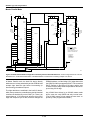
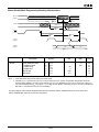
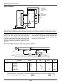
DONE is an open-drain output, configurable with or without an internal pull-up resistor. At the completion of configuration, the LCA circuitry becomes active in a synchronous order; DONE goes active High one cycle after the
IOB outputs go active.
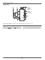
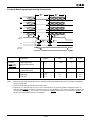
Once configuration is done, a High-to-Low transition of
this pin will cause an initialization of the LCA and start a
reconfiguration.
M0/RTRIG
As Mode 0, this input and M1, M2 are sampled before the
start of configuration to establish the configuration mode to
be used.
A Low-to-High input transition, after configuration is complete, acts as a Read Trigger and initiates a Readback of
configuration and storage-element data clocked by CCLK.
By selecting the appropriate Readback option when generating the bitstream, this operation may be limited to a
single Readback, or be inhibited altogether.
M1/RDATA
As Mode 1, this input and M0, M2 are sampled before the
start of configuration to establish the configuration mode to
be used. If Readback is never used, M1 can be tied directly
to ground or VCC. If Readback is ever used, M1 must use
a 5-kΩ resistor to ground or VCC, to accommodate the
RDATA output.
As an active Low Read Data, after configuration is complete, this pin is the output of the Readback data.
User I/O Pins that can have special functions.
M2
During configuration, this input has a weak pull-up resistor.
Together with M0 and M1, it is sampled before the start of
configuration to establish the configuration mode to be
used. After configuration, this pin is a user-programmable
I/O pin.
XTL1
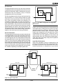
This user I/O pin can be used to operate as the output of
an amplifier driving an external crystal and bias circuitry.
XTL2
This user I/O pin can be used as the input of an amplifier
connected to an external crystal and bias circuitry. The I/
O Block is left unconfigured. The oscillator configuration is
activated by routing a net from the oscillator buffer symbol
output and by the MakeBits program.
CS0, CS1, CS2, WRT
These four inputs represent a set of signals, three active
Low and one active High, that are used to control
configuration-data entry in the Peripheral mode.
Simultaneous assertion of all four inputs generates a
Write to the internal data buffer. The removal of any
assertion clocks in the D0-D7 data. In Master mode,these
pins become part of the parallel configuration byte, D4, D3,
D2, D1. After configuration, these pins are userprogrammable I/O pins.
RCLK
During Master mode configuration RCLK represents a
“read” of an external dynamic memory device (normally
not used). After configuration, this is a user-programmable
I/O pin.
D0–D7
This set of eight pins represents the parallel configuration
input for the parallel Master mode. After configuration is
complete they are user programmed I/O pins.
A0–A15
During Master Parallel mode, these 16 pins present an
address output for a configuration EPROM. After configuration, they are user-programmable I/O pins.
DIN
During Slave or Master Serial configuration, this pin is
used as a serial-data input. In the Master or Peripheral
configuration, this is the Data 0 input. After configuration,
this is a user-programmable I/O pin.
HDC
During configuration, this output is held at a High level to
indicate that configuration is not yet complete. After configuration, this pin is a user-programmable I/O pin.
DOUT
During configuration this pin is used to output serialconfiguration data to the DIN pin of a daisy-chained slave.
After configuration, this is a user-programmable I/O pin.
LDC
During Configuration, this output is held at a Low level to
indicate that the configuration is not yet complete. After
configuration, this pin is a user-programmable I/O pin.
LDC is particularly useful in Master mode as a Low enable
for an EPROM, but it must then be programmed as a High
after configuration.
Unrestricted User I/O Pins.
I/O
An I/O pin may be programmed by the user to be an Input
or an Output pin following configuration. All unrestricted I/
O pins, plus the special pins mentioned on the following
page, have a weak pull-up resistor of 40 to 100 kΩ that
becomes active as soon as the device powers up, and
stays active until the end of configuration.
2-213