1
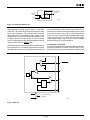
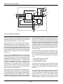
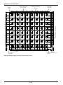
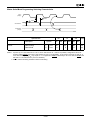
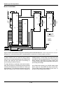
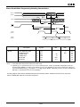
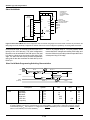
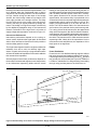
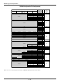
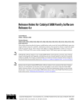
Master Parallel Mode Programming Switching Characteristics
A0-A15
(output)
1 TARC
D0-D7
2 TRAC
Byte n + 1
4 TRCD
3 TDRC
RCLK
(output)
6 TRCL
5 TRCH
CCLK
(output)
DOUT
(output)
D6
D7
Byte n - 1
Description
RCLK
From address invalid
To address valid
To data setup
To data hold
RCLK high
RCLK low
Symbol
1
2
3
4
5
6
TARC
TRAC
TDRC
TRCD
TRCH
TRCL
X5408
Min
Max
Units
0
200
ns
ns
ns
ns
ns
µs
60
0
600
4.0
Note: 1. CCLK and DOUT timing are the same as for slave mode.
2. At power-up, VCC must rise from 2.0 V to VCC min in less than 25 ms. If this is not possible, configuration can be delayed by holding RESET Low until VCC has reached 4.0 V (2.5 V for XC2000L). A very long VCC rise time of >100 ms, or
a non-monotonically rising VCC may require a >1-µs High level on RESET, followed by a >6-µs Low level on RESET and
D/P after VCC has reached 4.0 V (2.5 V for XC2000L).
This timing diagram shows that the EPROM requirements are extremely relaxed: EPROM access time can be longer than
4000 ns, EPROM data output has no hold time requirement
2-203