1
LCA internal timing generator (2 to 6 µs). Note that the
Clear time-out for a master-mode reprogram or abort does
not have the 4 times delay of the Initialization state. If a
daisy chain is used, an external RESET is required, long
enough to guarantee clearing all non-master mode devices. For XC2000-series LCA devices, this is accomplished with an external time delay.
• Input thresholds
• Readback disable
• DONE pull-up resistor
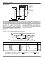
In some applications the system power supply might have
momentary failures which can leave the LCA control logic
in an invalid state. There are two methods to recover from
this state. The first is to cycle the VCC supply to less than
0.1 V and re-apply valid VCC. The second is to provide the
LCA device with simultaneous Low levels of at least 6 µs
on RESET and DONE/PROG pins after the RESET pin
has been High following a return to valid VCC. This guarantees that the LCA device will return to the Clear state.
Either of these methods may be needed in the event of an
incomplete voltage interruption. They are not needed for a
normal application of power from an off condition.
Input Thresholds
During configuration, all input thresholds are TTL level.
After configuration, input thresholds are established
as specified, either TTL or CMOS. The PWRDWN input
threshold is an exception; it is always a CMOS level input.
The TTL threshold option requires additional power for
threshold shifting.
Battery Backup
Because the control store of the Logic Cell Array is a
CMOS static memory, its cells require only a very low
standby current for data retention. In some systems, this
low data-retention current characteristic facilitates preserving configurations in the event of a primary power loss.
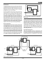
The Logic Cell Array has built in power-down logic which,
when activated, clears all internal flip-flops and latches,
but retains the configuration. All outputs are placed in the
high-impedance state, and all input levels are ignored. The
internal logic considers all inputs to be ones (High). Configuration is not possible during power down.
Power-down data retention is possible with a simple battery-backup circuit because the power requirement is
extremely low. For retention at 2.0 V, the required current
is typically on the order of 500 nA. Screening to this
parameter is available. To force the Logic Cell Array into
the power-down state, the user must pull the PWRDWN
pin Low and continue to supply a retention voltage to the
VCC pins of the package. When normal power is restored,
VCC is elevated to its normal operating voltage and
PWRDWN is returned to a High. The Logic Cell Array
resumes operation with the same internal sequence that
occurs at the conclusion of configuration. Internal I/O and
logic block storage elements will be reset, the outputs will
become enabled and then the DONE/PROG pin will be
released. No configuration programming is involved.
Special Configuration Functions
In addition to the normal user logic functions and interconnect, the configuration data include control for several
special functions:
Each of these functions is controlled by a portion of the
configuration program generated by the XACT Development System.
Readback
After a Logic Cell Array has been programmed, the configuration program may be read back from the device.
Readback may be used for verification of configuration,
and as a method of determining the state of internal logic
nodes during debugging. Three Readback options are
provided: on command, only once, and never.
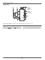
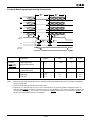
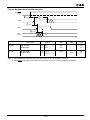
An initiation of Readback is produced by a Low-to-High
transition of the M0 / RTRIG (Read Trigger) pin. The CCLK
input must then be driven by external logic to read back the
configuration data. The first three Low-to-High CCLK
transitions clock out dummy data. The subsequent Lowto-High CCLK transitions shift the data frame information
out on the M1/RDATA (Read Data) pin. Note that the logic
polarity is always inverted, a zero in Configuration becomes a one in Readback, and vice versa. Note also that
each Readback frame has one Start bit (read back as a
one) but, unlike in Configuration, each Readback frame
has only one Stop bit (read back as a zero). The third
leading dummy bit mentioned above can be considered
the Start bit of the first frame.
All data frames must be read back to complete the process
and return the Mode Select and CCLK pins to their normal
functions. Readback data includes the state of all internal
storage elements. This information is used by the XACT
development system In-Circuit Debugger to provide visibility into the internal operation of the logic while the
system is operating. To read back a uniform time sample
of all storage elements, it may be necessary to inhibit the
system clock.
DONE Pull-up
The DONE / PROG pin is an open drain I/O that indicates
programming status. As an input, it initiates a reprogram
operation. An optional internal pull-up resistor may be
enabled.
The following seven pages describe the four configuration
modes in detail.
2-199