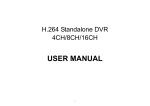
1
LevelOne
PLI-3410
200Mbps HomePlug AV Wireless Combo Adapter
User Manual
V1.0
Safety Warnings
1. Do not use the adapter in high humidity or high temperature environment.
2. Do not open or repair the case yourself.
3. Avoid using this product and all its accessories outdoor.
4. Place the adapter on a stable surface.
5. Only “HomePlug AV” compliant PowerLine Communication (PLC) adapter for remote access
is necessary.
6. Plug your LevelOne HomePlug AV device directly to the AC outlet on the wall. It is best to
avoid using extension power cable as it may possess noise filter or surge protector functions
that may cause interference that may impact the performance of the device.
Table of Contents
CHAPTER 1: PRODUCT ............................................................................................................................................................. 4
Introduction .......................................................................................................................................................................... 4
Features ................................................................................................................................................................................. 6
Specifications ...................................................................................................................................................................... 7
CHAPTER 2: INSTALLING THE ADAPTER ............................................................................................................................ 8
Language Setting ................................................................................................................................................................ 8
Package Content ................................................................................................................................................................. 8
Device Overview ................................................................................................................................................................ 10
Hardware Installation ....................................................................................................................................................... 12
Connecting the HomePlug Adapter .............................................................................................................................. 14
WPS configuration. ........................................................................................................................................................... 15
Networking Setup .............................................................................................................................................................. 16
Quick Start (Setup PowerLine Network)...................................................................................................................... 17
CHAPTER 3: BASIC NETWORK INSTALLATION .............................................................................................................. 20
Network Configuration ..................................................................................................................................................... 21
Configuring with your Web Browser ............................................................................................................................ 25
CHAPTER 3: UTILITY INSTALLATION ................................................................................................................................. 26
Utility Installation .............................................................................................................................................................. 27
Utility Configuration ......................................................................................................................................................... 35
Main Tab .............................................................................................................................................................................. 36
Privacy Tab ......................................................................................................................................................................... 40
QoS Tab ............................................................................................................................................................................... 41
Diagnostic Tab ................................................................................................................................................................... 42
About Tab ............................................................................................................................................................................ 44
CHAPTER 4: UI CONFIGURATION ........................................................................................................................................ 45
Status ................................................................................................................................................................................... 46
Statistic ................................................................................................................................................................................ 47
Internet Setting .................................................................................................................................................................. 48
Wireless Settings .............................................................................................................................................................. 50
Wireless Security/Encryption Settings ........................................................................................................................ 53
Advanced Wireless Settings .......................................................................................................................................... 56
Wi-Fi Protected Setup ...................................................................................................................................................... 57
Administration ................................................................................................................................................................... 65
Firmware Upgrade............................................................................................................................................................. 66
Settings Management ...................................................................................................................................................... 67
CHAPTER 5: TROUBLESHOOTING....................................................................................................................................... 68
Appendix: Product Support & Contact ........................................................................................................................ 69
Chapter 1: Product
Introduction
Thank you for purchasing PLI-3410 200Mbps HomePlug AV Wireless Combo
Adapter. Your new device is an unit that extends your wireless coverage through
power lines.
Compliant with the latest HomePlug AV standards, which support data speeds of up to
200Mbps, PLI-3410 can be used to bridge Ethernet devices such as modems, routers,
PCs, set-top- boxes, and game consoles, allowing users to share network access via
existing in-home power cabling.
What's unique is that the device has an extra built -in 802.11n Access Point, enabling
users to enjoy mobility, high-speed wireless connection and better coverage with no
more dead zones. Just plug PLI-3410 into any wall power socket, and you can easily
set up a secure wireless network by pressing the Wi -Fi Protected Setup (WPS) button.
Thus, the adapter can extend your wireless coverage through power lines for
multimedia applications such as online games, IPTV and audio streaming from room
to room.
• Extended Wireless Coverage
With an integrated 11n Wireless Access Point, the adapter can bridge wireless connections
of up to 6 times the speed and 6 times the wireless coverage of an 802.11b / g network device. It
supports a data rates up to 300Mbps and is also compatible with 802.11b / g equipment.
• Noise-immune Transmission
Unlike others, the device supports superior and noise-immune data transmission over in-home
electrical power lines. Even at the moment your family turns on an electronic device or turns off a
light, you won’t experience any interruption to latency-sensitive applications such as multimedia or
video being shared with your family in another room.
• 802.11g / 802.11n Wireless AP with WPA / WPS Support
With an integrated 802.11g / 802.11n Wireless Access Point, the device The supported features
of Wireless Protected Access (WPA-PSK/ WPA2-PSK) and Wireless Encryption Protocol (WEP)
enhance the security level of data protection and access control via Wireless LAN. The device also
supports the Wi-Fi Protected Setup (WPS) standard, allowing users to establish a secure wireless
network by simply pushing a button.
4
• Quality of Service (QoS) over PowerLine
Quality of Service control guarantees the transmission quality by automatically prioritizing data.
PLI-3410 automatically recognizes the bandwidth needs of voice and video applications. QoS
prioritizes the data to guarantee optimal transmission quality. TV and video images are received
and displayed with absolute smoothness. QoS also guarantees clear, instant transmission of voice
data, even when other applications are running on the network at the same time. QoS makes your
network a pleasure to use.
• Rich Management Interfaces
It supports flexible management interfaces with LAN, WLAN and PowerLine. Users can use WEB
GUI through the above interfaces to configure and manage the device.
• Web based GUI
It supports web based GUI for configuration and management. It is user-friendly.
• Firmware Upgradeable
Device can be upgraded to the latest firmware through the WEB based GUI.
5
Features
• Provides physical layer data rate of up to 200Mbps over existing in-home power lines
• Extended wireless coverage of up to 3 times the range of 802.11g products
• WPS (Wi-Fi Protected Setup) for easy setup
• Auto channel select
• Utilizes power line technology that takes advantage of the unused bandwidth of the electrical
wiring in your home
• Utilizes Quality of Service control
• Supports Triple Play applications such as IPTV, VoIP and high-speed Internet access
• Supports 10/100 BaseT Ethernet
• Compliant with the HomePlug PowerLine Alliance industry specifications
• Ideal for residential users
6
Specifications
Protocol
TDMA, CSMA/CA
Standard
Ethernet specification: IEEE 802.3, IEEE 802.3x, IEEE 802.3u,
Auto MDI/MDIX
Transmission Speed
200Mbps
Modulation
Supports OFDM - 1155 carriers,1024 / 256 / 64 / 16 / 8 QAM,
QPSK, BPSK and ROBO
Frequency Band
2MHz ~ 30MHz
Security
128-bit AES Link Encryption with key management for secure
power line communications
Encryption: NMK (Network Membership Key) used to authenticate/
access
Operating System
Rotating NEK (Network Encryption Key)
Windows XP / Vista / 7
Power Supplier
Other 10/100 Base-T Ethernet devices
Input: 100~240V AC, 50~60Hz
Physical Interface
Protection: OCP, OVP, SCP
AC power plug
2 fixed antennas
WPS button
Sync button
Reset button
RJ-45 compatible
LED display:
• WLAN
• POWER
• PLC (PowerLine Link/Act)
Physical Specifications
• ETH (Ethernet Link/Act)
Dimensions (W, D, H): 4.42” x 3.05” x 2.12” (112.4mm x 77.4mm x
53mm)
Operating Environment
Operating temperature: 00C ~ 400C
Storage temperature: -200C ~ 700C
Humidity: 20 ~ 95% non-condensing
7
Chapter 2: Installing the Adapter
Language Setting
Package Content
• PLI-3410 200Mbps HomePlug AV Wireless Combo Adapter
• Quick Start Guide
• CD User Manual
• Ethernet Cable
8
9
Device Overview
WLAN LED
Clip Socket
Power LED
PLC LED
ETH LED
WPS Button
SYNC Button
Ethernet Port
Reset Button
Power Plug
The Description of each labeled part is described in the table below.
WLAN LED
Lit green when the wireless function is enabled.
Power LED
Blinking when data is transmitted or received via WLAN.
Blinking quickly when WPS is proceeded.
Lit green when the device is power on.
PLC (Powerline
Link/Act) LED
Lit off when power is off.
Lit green when the power line sync is established.
Blinking quickly when data is transmitted or received via power line.
ETH (Ethernet
Link/Act) LED
WPS Button
Sync Button
Blinking after Sync button is pushed (see Sync Button descripted below).
Lit green when connected to an Ethernet device.
Blinking when data is transmitted or received via Ethernet port.
Push this button to trigger Wi-Fi Protected Setup function.
Used to establish a LAN network with other power line devices.
Push this button for 1~3 second(s) and release it to set device enter the
power line Sync state.
10
Reset Button
Press this button 1~3 second(s) to reset device to factory default settings.
Ethernet Port
Connect the HomePlug AV device with an Ethernet device (e.g. computer,
router, hub/switch, IP pone, IPTV set-top-box, gaming consoles…), using the
RJ-45 Ethernet cable included.
Plug into an AC outlet for power supply and to build a PowerLine network
with other HomePlug AV devices.
Install the clip into this socket.
Power Plug / AC
Power Cord
Clip Socket
Note: Please DO NOT remove or disassemble the socket clip frequently
as this may cause serious damage on your HomePlug AV device.
1
1
Hardware Installation
Refer to the following diagrams and instructions to install the clip with PLI-3410:
Example 1: EU clip
• Please check the lock instruction on your clip.
• If you got the “Triangle Lock”, refer to right diagram.
12
Example 2: UK clip
• Please check the lock instruction on your clip.
• If you got the “Circle Lock”, refer to right diagram.
1
3
Connecting the HomePlug Adapter
It is easy to connect PLI-3410 simply by performing the following instructions:
Power Connection
Plug PLI-3410 into the wall outlet/socket.
LAN & Wireless Connection
Connect the supplied RJ-45 Ethernet cable to the Ethernet port on PLI-3410 and the other side
to the device’s Ethernet interface.
You can enable wireless function to connect to the Wi-Fi devices through WPS configuration
interface or by pushing the WPS button of your PLI-3410.
14
WPS configuration.
Keep pushing the WPS button of PLI-3410. Then push WPS button of your wireless IP device, and
the Wi-Fi protection will be set up automatically. Likewise, do same steps for other wireless devices
having WPS button.
Example:
Wireless IP Devices
have WPS button
PLI-3410
Push
Push
1
5
Networking Setup
Refer to the following steps:
1. Connect a network cable to the bridge and then plug PLI-3410 into a power socket.
2. Then connect PLI-3410 to a laptop, modem, router or a set-top-box.
3. Create a secure network by simply pushing the SYNC button for 1~3 seconds.
Note: Plug/socket, power cable and input voltage/frequency may vary from country to
country.
16
Quick Start (Setup PowerLine Network)
Push Button usage
Sync Button is used to add a HomePlug device to a PowerLine network or enable it to join a
network by pressing the Sync Button of the device to turn it into Broadcast state or Join state.
There are 3 types of Sync Button trigger states:
1. Broadcast State: Enable LevelOne HomePlug AV device to provide information for another
HomePlug AV device to join its PowerLine network group (works even if it is the only
device existing within the network group).
2. Join State: This allows an ungrouped LevelOne HomePlug AV device to join an existing
PowerLine network group.
3. Ungroup State: Press the Sync Button for more than 10 seconds to detach the device from
its network group.
Application Scenarios
Scenario 1: A LevelOne HomePlug AV device A wants to form a network group with
another HomePlug AV device B
You can assign whichever device (A or B) to be in the Broadcast State and the other in the Join
State.
Example:
1. Press the Sync Button of device A for 1~3 seconds to turn it into Broadcast State, you should
find the Power LED blinks steadily signifying it is in Broadcast state.
2. Press the Sync Button of device B for 1~3 seconds to turn it into Join State, you should find
the Power LED blinks steadily signifying it is in Join state.
3. Wait for both devices to boot again (all LEDs will turn off and on) and when the PLC LEDs of
both devices lit steadily, you will now have these devices being in the same network group.
Scenario 2: A LevelOne HomePlug AV device wants to join an existing network group BC
Device A wants to join a network group “BC” currently consisting of device B and device C. Any
devices within the “BC” group can become the “Broadcast State” and device A will be the “Join
State”.
17
Example:
1. Press the Sync Button of device A for more than 10 seconds to make sure that it is detached
completely from any possible network group.
2. Press the Sync Button of device B or C of the BC network group for 1~3 seconds to turn it into
Broadcast State, you should find the Power LED blinks steadily signifying it is in Broadcast
state.
3. Press the Sync Button of device A for 1~3 seconds to turn it into Join State, you should find
the Power LED blinks steadily signifying it is in Join state.
4. Wait for the devices to boot again and when the PLC LEDs of both devices lit steadily, you
will now have device A joined with the BC network group.
Scenario 3: A LevelOne HomePlug AV device A of network group AD wants to join an
existing
network group BC
For a device which already belongs to a network group is to join with a different network group,
that device has to be ungrouped from its current attached group first.
Example:
1. Press the Sync Button of device A for more than 10 seconds to ungroup it from network group
AD.
2. Then press the Sync Button of device (B or C) of network group BC for 1~3 seconds to turn it
to Broadcast State, you should find the Power LED blinks steadily signifying it is in Broadcast
state.
3. Press the Sync Button of device A again for 1~3 seconds to turn it to Join State, you should
find the Power LED blinks steadily signifying it is in Join state.
4. Wait for the Sync LED of both devices A and (B or C) lit steadily. Now you will have device A
join the network group BC.
18
PowerLine Network Illustration
19
Chapter 3: Basic Network Installation
The HomePlug adapter can be configured through your web browser. A web browser is included as
a standard application in the following operating systems: Linux, Mac OS, Windows 98/NT/2000/XP/
Me/Vista, etc. The product provides an easy and user-friendly interface for configuration.
Please check your PC network components. The TCP/IP protocol stack and Ethernet network
adapter must be installed. If not, please refer to your Windows-related or other operating system
manuals.
There are ways to connect the device, either through an external repeater hub or connect directly
to your PCs. However, make sure that your PCs have an Ethernet interface installed properly prior
to connecting the device. You ought to configure your PCs to obtain an IP address through a DHCP
server or a fixed IP address that must be in the same subnet as the device. The default IP address
of the device is 192.168.1.1 and the subnet mask is 255.255.255.0 (i.e. any attached PC must
be in the same subnet, and have an IP address in the range of 192.168.1.1 to 192.168.1.252). The
best and easiest way is to configure the PC to get an IP address automatically from the device
using DHCP. If you encounter any problem accessing the HomePlug AV adapter web interface it is
advisable to uninstall your firewall program on your PCs, as they can cause problems accessing
the IP address of the device. Users should make their own decisions on what is best to protect their
network.
Please follow the following steps to configure your PC network environment.
20
Network Configuration
Configuring PC in Windows Vista / 7
1. Go to Start. Click on Network.
2. Then click on Network and
Sharing Center at the top bar.
3. When the Network and Sharing
Center window pops up, select
and click on Manage network
connections on the left window
column.
4. Select the Local Area Connection,
and right click the icon to select
Properties.
21
5. Select Internet Protocol Version 4
(TCP/IPv4) then click Properties.
6. In the TCP/IPv4 properties window,
click Use the following IP address
and Use the following DNS server
address radio buttons. Then click
OK to exit the setting.
7. Click OK again in the Local Area
Connection Properties window to
apply the new configuration.
22
Configuring PC in Windows XP
1. Go to Start > Control Panel (in Classic
View). In the Control Panel, double-click
on Network Connections
2. Double-click Local Area Connection.
3. In the Local Area Connection Status
window, click Properties.
4. Select Internet Protocol (TCP/IP) and
click Properties.
5. Click Use the following IP address and
Use the following DNS server address
radio buttons.
6. Click OK to finish the configuration.
23
Factory Default Settings
Before configuring your adapter, you need to know the following default settings.
Web Interface (Username and Password)
Username: admin
Password: admin
The default username and password are “admin” and “admin” respectively.
Group Name: HomePlugAV
Device LAN IP settings
IP Address: 192.168.1.1
Subnet Mask: 255.255.255.0
DHCP server
DHCP server is disabled.
Start IP Address: 192.168.1.2
24
Internet Access Configuration
To configure this device for internet access, you must have IE 5.0 / Netscape 4.5 or above
installed on your computer. There is basically one way to configure your device before you are
able to connect to the internet: Web Interface. Configuration of this method will be discussed in
detail in the following section.
Configuring with your Web Browser
Open your web browser, enter the IP address of your Ethernet Adapter which by default is
192.168.1.1, and click “Go”. A user name and password window prompt will appear. The default
username and password are “admin” and “admin”.
Congratulations! You are now successfully logon to the PLI-3410 200Mbps HomePlug AV
Wireless Combo Adapter!
If the authentication succeeds, the homepage will appear on the screen.
25
Chapter 3: Utility Installation
The utility can be used on the following Windows platform: Windows 2000/XP/Vista/7.
1. Place the LevelOne PLI-3410 HomePlug AV 200 Utility auto-installation CD into your CDROM/DVD-ROM drive.
2. Click on Utility for Easy Installation to install the utility.
26
Utility Installation
1. After clicking on Utility for Easy Installation, the installation wizard will appear. Click Next.
27
2. You may define the location of the installation folder using the Browse button, however it is
highly recommended that you use the default location. In addition, you can also choose to
install PLI-3410 200Mbps HomePlug AV Wireless Combo Adapter Utility only for yourself or for all
the users who share your PC. When all necessary items are properly selected, press Next to
proceed.
3. Press Next to confirm and start the installation.
28
29
4. While the utility installation is in progress, the system will automatically prompt you to install the
WinPcap program in a separate window pop-up. Install this program in order for the utility to work
well.
5. While the utility installation is in progress, the system will automatically prompt you to install the
WinPcap program in a separate window pop-up. Install this program in order for the utility to work
well.
30
6. When the WinPcap installation window pops up, click Next to proceed with the installation.
7. Click on Next to proceed to the next step.
31
8. Read through the license agreement then click on I Agree button to accept the agreement
term.
9. If you want the WinPcap driver run automatically when booting, please tick Automatically start the
WinPcap driver at boot time. Then click on install to continue the installation.
32
10. When the WinPcap installation is done, click on Finish to close the window.
33
11. When the WinPcap installation is done, you will have also completed the LevelOne PLI-3410
200Mbps HomePlug AV Wireless Combo Adapter Utility installation as well. You may now click on
the close button of the Utility installation window to finish the process.
34
Utility Configuration
Accessing LevelOne PLI-3410 HomePlug AV 200 Utility
Click the icon of PLI-3410 on desktop
LevelOne PLI-3410 200Mbps HomePlug AV Wireless Combo Adapter Utility consists of 6 screens
accessed through these panel tabs. The 5 panels are Main, Privacy, QoS, Diagnostics and About
located on the top left corner of the program for configuration convenience.
35
Main Tab
The Main Tab screen lists all the PowerLine devices that are connected to the host computer when
the utility is running. The top left window panel shows all the local HomePlug AV devices that are
connected to the computer’s NIC (Network Interface Card). Normally, only one device will be seen
on the list. If there is more than one local device being connected, user can select the local device by
clicking on it and then click the Connect button to its right to use it to connect to the internet. Once
connected to the local device, the utility will automatically scan the power line periodically for other
newly connected HomePlug AV devices. If no local HomePlug AV devices are discovered, the status
area above the connect button will indicate with a message "NO HOMEPLUG ADAPTERS
DETECTED". The bottom window panel displays all the HomePlug remote devices that are detected
on the current network. The total number of remote devices connected on the same network can be
found on top of the Remote device panel. Within this panel, you can also find some useful
information of each remote device such as its connection quality, transfer rate and MAC address.
The Network type (Public or Private) is also displayed based on the network status of the local
device. The scan status option is displayed on the top right corner above the Remote devices panel
showing whether the AutoScan function is turned ON or OFF. The following information is displayed
for all devices that appear in the lower panel:
Device Name:
Show the default device name. User can change the name by either clicking on the rename button or
by clicking on the name and editing in-place. An icon is usually shown with the device name.
Password (*required when one needs to change the Private Network Name of the devices) This
column is left blank by default. The password will be displayed only after it has been entered. For
36
detail information on password setup, please refer to section on Password Setup Instruction. Each
device comes with a unique password and it can be found at the back of the device itself.
Quality:
Display the overall quality of the data transmission rate. When the transmission rate is good, the
number of line appear will increase.
Rate (Mbps):
Display the data transmission rate of each device.
MAC Address:
Show the Remote device MAC address.
Password Setup Instructions:
This feature grants users the access level to change the Private Network Name of both the local &
the remote HomePlug AV devices. Password is required if one is to change the Private Network
Name of each devices within the PowerLine network in order for all devices to be able to
communicate & synchronize with each other within the network.
37
1. To enter a password for a specific device, select the device and click on the Enter Password
button at the bottom of the lower panel to call up the Set Device Password dialog box.
2. Then type in the password in the blank provided and press OK.
Note: The password of each HomePlug device can be found at the back of the device.
38
3. If the password entered is not recognized or unacceptable, an error message box will pop up
prompting user to change the password. Click OK then re-enter the password again.
4. If the password entered is correct, you will see that the password will be displayed next to the
device.
39
Privacy Tab
Privacy Tab allows user the convenience to manage the security of the private PowerLine network.
In addition, user can also utilize this feature to add a new HomePlug device to the private network
instead of manually adding the device using its SYNC button. In order to add devices to the network
through the utility GUI, Private Network Name of each device is required to be the same with the
local device.
All HomePlug AV devices are shipped using a default logical network name “HomePlugAV”. The
Privacy tab screen allows user to change its default public network type to a private network by
changing the network name (network password) of the device. The user can always reset the
network type to HomePlug network (Public) by entering “HomePlugAV” as the network name or by
clicking on the Use Default button.
Note: Changing the network name to anything other than HomePlugAV will show the network
type on the main screen as Private.
Set Local Device Only button can be used to change the Private Network Name of the local device.
If a new Private Network Name is entered, all associated devices seen on the Main Tab previously
will no longer be present in the new network, thus causing the local device unable to communicate
with other devices which were in the network previously.
Set All Devices button is used to change the Private Network Name of all devices that appear on the
Main tab screen whose Device Password had been entered correctly. For devices whose device
passwords were not entered, this operation will fail and will report a failure message.
40
QoS Tab
This function allows user the flexibility to manage the bandwidth usage for each HomePlug device.
The higher the QoS priority the more bandwidth usage is allocated to that particular device.
To set the QoS priority of each device:
1. Click to select the type that you want to set the QoS priority.
2. In the Priority setting field, click on Add/Modify button, then enter the IP address/MAC address
and drag the Priority slider to either Low, Normal, Medium or High position. When the position of the
slider is set, click Confirm to save the settings. You will see a new entry displayed in the table above.
3. After the setting of QoS is completed, click Apply to confirm the setting.
41
Diagnostic Tab
The Diagnostics Tab screen shows System information and a history of all remote devices seen over
a period of time. This screen is available for OEM/ODM Customization. The Upper panel shows
technical data concerning software and hardware present on the host computer which were used for
communication via HomePlug device on the PowerLine network.
The data includes the following:
• Operating System Platform/Version
• Host Network Name
• MAC Address of all NICs (Network interface card) connected to the host
• Identify versions of all Driver DLLs and Libraries used (NDIS) and optionally
• MAC Firmware Version
• MAC addresses of all devices connected locally to the host
• Version of the Configuration Utility
• Microprocessor
The Lower panel contains a history of all remote devices seen on the computer over a certain period
of time. All devices that were on the PowerLine network are listed here along with a few other
parameters. Devices that are active on the current logical network will show a transmission rate in
the Rate column; devices on other networks, or devices that may no longer exist are shown with a
“?” in the Rate column. The following remote device information is available from the diagnostics
screen:
• Device Alias Name
• Device MAC Address
• Device Password
42
• Transfer rate
• Device Last Known Network name
• Vendor name
• Date device last seen on the network
• MAC Firmware version
The diagnostics information displayed may be saved as a text file for later use, or it can be printed
for reference. Devices, which are not part of the network anymore, can be deleted using the delete
button. A warning window will pop up requesting for a confirmation when we try to delete a device
which password has been entered.
43
About Tab
The About screen shows the software version.
Under the Preferences panel, user can check the AutoScan box to turn on the Auto Scan function or
check off the box to turn off the Auto Scan function.
44
Chapter 4: UI Configuration
Once you have logged on to your adapter GUI via your web browser, you can begin to configure the
device according to your needs. On the configuration homepage, the left navigation pane provides
the links to different setup pages.
♣ Status (Status / Statistic)
♣ Internet Setting (LAN)
♣ Wireless Settings (Basic / Security / Advanced / WPS / Station List)
♣ Power Line Settings (Status / Privacy / QoS)
♣ Administration (Management / Upload Firmware / Settings Management)
Each of these setup pages will be discussed in detail in sections that follow ahead.
45
Status
System Information
Model Name: Displays the model name.
Firmware Version: Displays the firmware version for this device.
System Up Time: Records system up-time.
LAN
LAN IP Address: The current IP on this device.
LAN Netmask: The current subnet mask on this device.
Note: Click the LAN IP Address or LAN Netmask link to change the settings.
LAN MAC Address: The MAC address for the device.
Wireless LAN
WLAN Service: Status of the WLAN connection.
SSID: A unique name used to identify the wireless LAN to which a user wants to connect.
Channel: The current status in WAN interface.
Note: Click the WLAN Service, SSID or Channel link to change the settings.
Power Line
Power Line Service: State of power line.
46
Connected Device: Displays the number of the remote power line device(s).
Note: Click the Power Line Service or Connected Device link to display the power line
information.
Statistic
Memory
Memory total: Displays the total memory size of the device (in bytes).
Memory left: Displays the amount of memory left (in bytes).
LAN
LAN Rx packets: Displays the number of received packets.
LAN Rx bytes: Displays the received packet traffic (in bytes).
LAN Tx packets: Displays the number of transferred packets.
LAN Tx bytes: Displays the transferred packet traffic (in bytes)
47
Internet Setting
LAN
IP Address: Enter the preferred IP address. Default is 192.168.1.1.
Subnet Mask: Enter the preferred subnet mask. Default is 255.255.255.0.
LAN2: This function enables the creation of multiple virtual IP interfaces for this device. It helps
to connect two or more local networks to the ISP or remote node. In this case, an internal device
is not required. Default setting is Disable. If you want to active IP Alias function, please select
Enable.
LAN2 IP Address: Specify an IP address for this virtual interface.
LAN2 Subnet Mask: Specify a subnet mask for this virtual interface.
DHCP Type: You can disable or enable the function with DHCP server. The default type is
Disable. The configuration of each item is described in DHCP Server section.
UPNP: UPnP offers peer-to-peer network connectivity for PCs and other network devices, along
with the feature to control data transfer between devices. Default is Disable.
♣ Enable: Select to activate the device’s UPnP function.
♣ Disable: Select to inactivate the device’s UPnP function.
Click Apply to save the changes or Cancel to recover the default setting.
48
DHCP Server
DHCP allows networked devices to obtain information on the parameters of IP, Netmask, and so
forth through the Ethernet Address of the device.
DHCP Type: To configure the device’s DHCP Server, select Server from the DHCP Type dropdown menu and you can then configure parameters of the DHCP Server.
DHCP Start IP/ End IP: Enter the starting and ending IP address of the range of IP addresses
that you want the DHCP server to assign to DHCP clients. The default DHCP IP range is
192.168.1.2 to 192.168.1.50.
DHCP Subnet Mask: Enter the subnet mask for the network address that you specified. The
default is 255.255.255.0.
DHCP Lease Time: Enter the time value (in seconds) that you want the assigned IP address to be
valid for. The DHCP client must obtain a new IP address from the DHCP server when this value
expires.
Statically IP Assigned: You can map the MAC address for stations that you want to always be
assigned the same IP address. Mapped IP addresses must be outside the DHCP start/end IP
range. You can configure up to 3 sets of MAC and IP addresses in this table.
49
Wireless Settings
When you click this item, the column will expand to display the sub-items that will allow you to
configure your wireless settings.
Basic, Security, Advanced, WPS and Station List
The function of each configuration sub-item is described in the following sections.
Basic Wireless Settings
Wireless Network
WLAN Service: Default setting is Enable. If you do not have any wireless, select Disable.
Network Mode: The default setting is 11b/g/n mixed mode. If you do not know or have both 11b,
11g and 11b devices in your network, please left this mode selected. If you have only 11b card,
please select 11b only from the drop-down menu. If you have only 11g card, please select 11g only
from the drop-down menu. If you have both 11b and 11g card, please select 11b/g mixed mode.
Network Name (SSID): The SSID is the unique name of a wireless access point (AP) used to
distinguish one from another. For security purpose, you should change the default SSID to a
unique ID name that is difficult to guess. Make sure your wireless clients have exactly the SSID as
the device in order to connect to your network.
Note: It is case sensitive and can be up to 32 characters.
Broadcast Network Name (SSID): It is used to broadcast its SSID on the network so that when
50
a wireless client searches for a network, the device can be discovered and recognized. Default
setting is Disable.
♣ Enable: When enabled, the SSID is broadcast for wireless users to use.
♣ Disable: When disabled, prevents the SSID broadcast from being seen by wireless users.
Frequency Channel: Select the wireless connection ID channel that you would like to use.
Note: Wireless performance may degrade if the selected ID channel is already being
occupied by other AP(s).
Channel Bandwidth: Select either 20 MHz or 20/40 MHz for the channel bandwidth. The higher
the bandwidth the better the performance will be.
BSSID: Displays the MAC address of the device.
Rate: Available when 11b/g mixed mode, 11b only and 11g are selected in Network Mode. Select
the data transmission rate from the drop-down menu. Default is Auto.
Wireless Distribution System (WDS)
It is a wireless access point mode that enables wireless link and communication with other access
points. It is easy to install simply by defining the peer’s MAC address of the connected AP. WDS
takes advantage of the cost saving and flexibility which no extra wireless client device is required to
bridge between two access points and extending an existing wired or wireless infrastructure network
to create a larger network.
WDS Mode: You can disable or enable the WDS functionality. Default setting is Disable.
Lazy Mode
WDS Mode: Select Lazy Mode from the drop-down menu. In this case, WDS peers can be autodetected.
Phy Mode: Select the appropriate mode from the drop-down menu. There are 4 options: CCK,
OFDM, HTMIX and GREENFIELD.
Encrypt Type: You can select None or other types: WEP, TKIP or AES. When WEP, TKIP or AES
is selected, the Encrypt Key field will display to allow you to set an encryption key.
51
Bridge Mode
WDS Mode: Select Bridge Mode from the drop-down menu. In this case, AP adapter acts as a
wireless bridge and will not respond to wireless requests.
Phy Mode: Select the appropriate mode from the drop-down menu. There are 4 options: CCK,
OFDM, HTMIX and GREENFIELD.
Encrypt Type: You can select None or other types: WEP, TKIP or AES. When WEP, TKIP or AES
is sleeted, the Encrypt Key field will display to allow you to set an encryption key.
AP MAC Address: Enter the associated AP’s MAC Address(es) in this field and the following
fields. It is important that your peer’s AP must include your MAC address in order to acknowledge
and communicate with each other.
Repeater Mode
WDS Mode: Select Repeater Mode from the drop-down menu. In this case, AP adapter acts as a
repeater and interconnects between access points.
Phy Mode: Select the appropriate mode from the drop-down menu. There are 4 options: CCK,
OFDM, HTMIX and GREENFIELD.
Encrypt Type: You can select None or other types: WEP, TKIP or AES. When WEP, TKIP or AES
is selected, the Encrypt Key field will display to allow you to set an encryption key.
AP MAC Address: Enter the associated AP’s MAC Address(es) in this field and the following
fields. It is important that your peer’s AP must include your MAC address in order to acknowledge
and communicate with each other.
52
Wireless Security/Encryption Settings
Security Mode: You can disable or enable the wireless security function using WEP or WPA for
wireless network protection. The default mode of wireless security is disabled. Please refer to the
Security Mode section for detail description.
Access Policy
Policy: Select from the drop-down menu to choose whether the entered MAC Address should be
allowed to pass (Allow) or to be blocked (Reject).
Note: When the Policy is selected Allow, all the MAC addresses you entered in the Add a
station MAC address field will be pass; when the Policy is selected Reject, all the MAC
addresses you entered in the Add a station MAC address field will be blocked.
Add a station MAC address: Enter the MAC address of the wireless client.
53
Security Mode
WEP OPEN / WEP SHARED / WEP AUTO
Security Mode: Select WEP OPEN, WEP SHARED or WEP AUTO from the drop-down menu.
Wire Equivalence Protection (WEP)
Default Key: Select the encryption key ID.
WEP Keys (1~4): Enter the key to encrypt wireless data. To allow encrypted data transmission,
the WEP Encryption Key values on all wireless stations must be the same as the device. There
are four keys for your selection. The input format is in Hex or ASCII style, 5 and 13 ASCII codes
are required for WEP64 and WEP128 or 10 and 26 Hex codes are required for WEP64 and
WEP128 respectively.
54
WPA-PSK / WPA2-PSK / WPAPSK/WPA2PSK mix mode
Security Mode: Select WPA-PSK or WPA2-PSK from the drop-down menu.
WPA
WPA Algorithms: There are 3 types of the TKIP, AES & TKIPAES (not available in WPA-PSK
mode).
Pass Phrase: Enter a pass phrase to access the network. It can be a password like “12345678” or
a pass phrase, from 8 to 63 case-sensitive characters.
Key Renewal Interval: The period of renewal time (in seconds) for changing the security key
automatically between wireless client and Access Point (AP). Default value is 3600 seconds.
55
Advanced Wireless Settings
Advanced Settings
TX Power: TX Power measurement that enhances the wireless transmission signal strength. You
can adjust this power level from minimum (0) to maximum (100). Default is 100.
Tx Burst: This feature is used to activate the transmitted time slot to increase transmission
throughput. Default is Enable.
Wi-Fi Multinedia
WMM Capable: This feature is used to control the prioritization of traffic according to 4 Access
categories: Voice, Video, Best Effort and Background. Default is Enable.
APSD Capable: Automatic Power Save Delivery (APSD) is an efficient power management
mechanism and is very useful for a VoIP phone. You can select enable or disable this feature.
Default is Disable.
IGMP Snooping
IGMP Snooping Service: Allows a layer 2 switch to manage the transmission of any incoming
IGMP multicast packet groups between the host and the router. Default is set to enable.
56
Wi-Fi Protected Setup
WPS feature is designed to ease setup of security enabled WiFi networks in small offices or home.
It supports methods to you to set a network and enable security by entering a PIN or pushing a
button.
WPS Config
WPS: Default setting is Enable. If you do not want to activate this functionality, please select
Disable and click Apply to confirm the setting.
WPS Progress
WPS mode: Define the WPS mode by PIN code or PBC.
♣ PIN: Select PIN (Personal Identification Number) mode process to connect to the device.
♣ PBC: Select PBC (Push Button Communication) mode process to connect to the device.
Note: You can enable WPS PBC mode through WPS configuration interface as above or
by pushing the WPS button of your HomePlug AV 200 Ethernet Adapter for more than 1
seconds and the WPS will establish the connection automatically.
Role: Select to be the Registrar or Enrollee for this device.
PIN: When PIN mode is selected, this field is displayed to allow you to enter the PIN code which
the device uses to authenticate other WPS-enabled wireless devices.
Click Apply to save the change.
57
WPS Summary
WPS Current Status: Displays the WPS status.
WPS Configured: Displays the current WPS configuration status
WPS SSID: Displays the WPS network name.
WPS Authentication Mode: Displays the authentication mode for WPS.
WPS Encryption Type: Displays the encryption type for WPS.
WPS Default Key Index: Displays the Default Key Index. WPS
Key(ASCII): Displays the WPS key (ASCII characters). AP PIN:
Displays the Access Point's PIN number.
58
Station List
The Station List displays the Wireless Network information.
Wireless Network
MAC Address: The Media Access Control (MAC) addresses for each device on your WLAN.
Aid: The association ID.
PSM: The power save mode.
MimoPS: The MIMO power save mode. MIMO, Multiple-input and multiple-output, is the use of
multiple antennas at both the transmitter and receiver to improve communication performance.
MCS: The Modulation and Coding Scheme.
BW: The Network Bandwidth.
59
Power Line Settings
Status
Local Device
Model: Displays the model name for the local power line device.
Firmware: Displays the version number of firmware on the local power line device.
MAC Address: Displays the MAC address of the local power line device.
When you have successfully synchronized two HomePlug AV adapters through the PowerLine,
the information of both adapters will display on the Power Line Status screen.
In the illustration above, there are 1 local device and 1 remote device in the same power loop.
Remote Device
MAC Address: Displays the MAC address for the remote device.
60
Security
Security Settings
New Network Password (Name): Enter the new network password (name) to apply to the local
HomePlug adapter. This allows the HomePlug adapters that have the same network password
in the PowerLine network to communicate with each other.
Click Apply to confirm the setting.
QoS
Wired networks use QoS to help traffic flow more smoothly. On this screen, you can prioritize
traffic passing through your adapter based on the device it is intended for by setting MAC address
and the level of priority.
Local Device
MAC Address: Displays the MAC address.
Network card MAC Address: Enter the network card MAC address.
Priority: Select a priority from the drop-down menu.
Add: Press this button to add a new MAC address.
Click Apply to confirm the settings.
Note: If you set no QoS setting, the QoS setting will be returned to the factory
61
default settings when you click on Apply button.
Note: When there is no QoS policy on the device, a warming message will pop-up as below
after clicking Apply.
QoS example:
The above illustration is an example for QoS topology, commonly in the home and small office
environment.
To set the QoS policy, perform the following steps:
1. Select Power Line Settings > QoS. In the Power Line QoS Settings screen, add new policy for
QoS.
2. Run the “Command Prompt” (From the Windows desktop click Start > Run, type cmd and click
OK.). At the command prompt, type ipconfig /all and press Enter. Look for the line Physical
Address.
62
Enter “ipconfig/all” here
00:11:2F:23:23:42
Your MAC address
3. Go back to Power Line QoS Settings screen, enter you network card MAC address and choose
the priority. Click Add button to add this new rule. You will see the new address(s) displayed in
the QoS Policy table.
Note: Make sure that the MAC Address that you entered is correct. (A MAC address uses 6
pairs of hexadecimal characters, for example 00:11:22:3A:4B:56.)
4. You can change the priority of the QoS rule(s) from the Priority drop-down menu or remove the
rule(s) by clicking on Delete button next to the item you want to delete.
5. Click Apply to confirm the configuration.
63
Note: Do NOT perform any more actions in QoS setting process.
6. Once the setting is complete, you will be returned to the Power Line QoS Settings page.
64
Administration
System Management
Administrator Settings
Account: You are allowed to set your own account name. Default is admin.
Password: You are allowed to set your own password. Default is admin.
Click Apply to save the changes.
65
Firmware Upgrade
Upgrading the newly improved version of the firmware allows you to get the advantage to use newly
integrated features.
Update Firmware
Location: Click on Browse to select the new firmware image file you have downloaded to your PC.
Once the correct file is selected, click Apply to update the firmware to your device.
Note: Do NOT perform any more actions while the firmware is being upgraded.
The system will automatically reboot once the upgrade is complete. You will be returned to the
Status page.
66
Settings Management
These functions allow you to save a backup of the current configuration of your device to a defined
location on your PC, to restore a previously saved configuration, or to restart your device with the
factory default settings. This is useful if you wish to experiment with different settings, knowing
that you have a backup in hand in case any mistakes occur. Besides, you can restart the device
to factory default setting after you have accidentally changed your settings that may result in
undesirable outcome.
Export Settings
Export Button: Click on Export to select where on your local PC you want to store your setting file.
You may also change the name of the file if you wish to keep multiple backups.
Note: It is advisable that you backup your device configuration before making any changes
to your device configuration.
Import Settings
Settings file location: Click on Browse to select a file from your PC to restore. You should only
restore your device setting that has been generated by the Backup function which is created with
the current version of the device firmware. Settings files saved to your PC should not be manually
edited in any way.
Select the settings files you wish to use, and press Import to load the setting into the device.
Load Factory Defaults
Load Default Button: Click on Load Default to initiate the restart process. After restarting, please
wait several minutes to let the selected setting applied to the system.
You may also reset your device to factory settings by holding the small Reset pinhole button more
than 2 seconds.
67
Chapter 5: Troubleshooting
If your device is not functioning properly, please refer to the suggested solutions provided in this
chapter. If your problems persist or the suggested solutions do not meet your needs, please
kindly contact your service provider for support.
Problems with the device
Problem
Suggested Solution
I forgot my password.
First try entering the default user name and password:
User Name: admin; Password: admin. (Both the User Name and
Password are case sensitive, so make sure that CAPS LOCK is
not on when entering this information.)
If this fails, restore your HomePlug AV device to its factory
default settings and then enter the default user name and
password.
I can not access the LOGIN • Ensure you are using the correct IP address. (Default is
Web Configuration Interface. 192.168.1.1.)
• Check the hardware connections and ensure all LEDs are
behaving as excepted.
• Ensure your computer’s IP address is in the same subnet as
the HomePlug device.
• Check to see if your browser has Java, JavaScript, or ActiveX
enabled. If you are using Internet Explorer, click Refresh to
ensure that the Java applet is loaded.
• Try closing the browser and re-launching it.
• Reset the device to factory defaults and try to access the
HomePlug adapter with the default IP address.
How do I reset the
There are two ways to reset factory default settings:
HomePlug AV200 adapter?
• Hardware Reset
To perform a hardware reset, hold down the reset button for
more than 2 seconds, and release it.
• Software Reset
To initiate a software reset, select Administration > Settings
Management and click on Load Default button to initiate the
restart process. Then wait several minutes.
Note: Restoring to factory default will wipe out all the
configurations you have previously set. You are strongly
advised to create a backup copy of the settings before
resetting the device.
I can not start my HomePlug Please check your power supply is working. HomePlug device
device.
operates from the power supplied by the home electrical wiring
and can not operate without a working power supply.
68
My HomePlug device is
unable to detect my other
HomePlug device.
This may due to the accidental change of the device password.
Access the HomePlug AV web interface and select Power Line
Settings > Privacy. Fill in the password (case sensitive) in the
blank. Then repeat the same procedure to the other HomePlug
device via Utility or web interface.
Appendix: Product Support & Contact
If you come across any problems please contact the dealer from where you purchased your
product.
Contact LevelOne
Worldwide:
http://global.level1.com
MAC OS is a registered Trademark of Apple Computer, Inc.
Windows 98, Windows NT, Windows 2000, Windows Me, Windows XP and Windows Vista are registered
Trademarks of Microsoft Corporation.
69