1
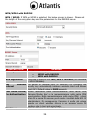
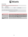
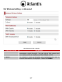
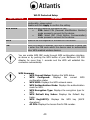
ITALIANO Questo prodotto è coperto da garanzia Atlantis della durata di 2 anni. Per maggiori dettagli in merito o per accedere alla documentazione completa in Italiano fare riferimento al sito www.atlantis-land.com. ENGLISH This product is covered by Atlantis 2 years warranty. For more detailed informations please refer to the web site www.atlantis-land.com. For more detailed instructions on configuring and using this device, please refer to the online manual. FRANCAIS Ce produit est couvert par une garantie Atlantis de 2 ans. Pour des informations plus détaillées, référez-vous svp au site Web www.atlantis-land.com. DEUTSCH Dieses Produkt ist durch die Atlantis 2 Jahre Garantie gedeckt. Für weitere Informationen, beziehen Sie sich bitte auf Web Site www.atlantis-land.com. ESPAÑOL Este producto esta cubierto por Atlantis con una garantía de 2 años. Para mayor información diríjase a nuestro sitio Web www.atlantis-land.com. 2 INDEX 1. Product Overview ............................................................................. 10 1.1 System Requirements ................................................................ 10 2. Package Contents ............................................................................. 11 3. Hardware Installation ........................................................................ 11 4. LED ................................................................................................. 12 5. Cabling ............................................................................................ 14 6. Default SETTINGS ........................................................................... 15 7. INTERNET EXPLORER CONFIGURATION ............................................ 16 8. TCP/IP CONFIGURATION .................................................................. 16 Configuring PC (Windows 2000) ...................................................... 16 Configuring PC (Windows XP)......................................................... 16 Configuring PC (Windows Vista) ..................................................... 17 Configuring PC (Windows 7)........................................................... 17 9. WEB Configuration ........................................................................... 17 9.1 Status -> Status ........................................................................ 20 9.2 Status -> Statistics .................................................................... 22 9.3 LAN Settings -> LAN .................................................................. 23 9.4 Wireless Setting -> Basic............................................................ 25 Wireless Distribution System (WDS).................................................. 28 WDS->Lazy Mode ............................................................................ 28 WDS->Bridge Mode ......................................................................... 29 WDS->Repeater Mode ..................................................................... 30 9.5 Wireless Setting -> Security ....................................................... 31 WEP (Wired Equivalent Privacy) ....................................................... 32 WPA-PSK/WPA2-PSK (Wifi Protected Access)..................................... 33 WPA/WPA2 with RADIUS ................................................................. 34 Access Policy 36 9.6 Wireless Setting -> Advanced ..................................................... 37 10. Support .......................................................................................... 52 APPENDIX A: Troubleshooting ............................................................... 53 A.1 Using LEDs to diagnose problems ............................................... 53 A.1.1 Power LED ............................................................................. 53 A.1.2 LAN LED................................................................................. 53 A.2 WEB Configurator ...................................................................... 53 A.4 Login Username e Password ....................................................... 54 3 A.5 LAN Interface ............................................................................ 54 A.6 Wireless 55 A.7 PowerLine ................................................................................. 57 APPENDIX B: Sync Button ..................................................................... 60 Application Scenarios ....................................................................... 60 APPENDIX C: Connect to a network using Windows client ....................... 62 APPENDIX D: Country Channel List ........................................................ 64 APPENDIX E: Technical Specifications .................................................... 65 A02-PL303-WN_ME01 (v1.00 April 2010) 4 Copyright Statement No part of this publication may be reproduced, stored in a retrieval system, or transmitted in any form or by any means, whether electronic, mechanical, photocopying, recording or otherwise without the prior writing of the publisher. Windows™ 98SE/2000/ME/XP/VISTA are trademarks of Microsoft® Corp. Pentium is trademark of Intel. All copyright reserved. The Atlantis logo is a registered trademark of Atlantis. All other names mentioned mat be trademarks or registered trademarks of their respective owners. Subject to change without notice. No liability for technical errors and/or omissions. Wireless LAN, Health and Authorization for use Radio frequency electromagnetic energy is emitted from Wireless LAN devices. The energy levels of these emissions however are far much less than the electromagnetic energy emissions from wireless devices like for example mobile phones. Wireless LAN devices are safe for use frequency safety standards and recommendations. The use of Wireless LAN devices may be restricted in some situations or environments for example: On board of airplanes, or In an explosive environment, or In case the interference risk to other devices or services is perceived or identified as harmful In case the policy regarding the use of Wireless LAN devices in specific organizations or environments (e.g. airports, hospitals, chemical/oil/gas industrial plants, private buildings etc.) is not clear, please ask for authorization to use these devices prior to operating the equipment. Regulatory Information/disclaimers Installation and use of this Wireless LAN device must be in strict accordance with the instructions included in the user documentation provided with the product. Any changes or modifications made to this device that are not expressly approved by the manufacturer may void the user’s authority to operate the equipment. The Manufacturer is not responsible for any radio or television interference caused by unauthorized modification of this device, of the substitution or attachment. Manufacturer and its authorized resellers or distributors will assume no liability for any damage or violation of government regulations arising from failing to comply with these guidelines. CE Mark Warning In a domestic environment, this product may cause radio interference, in which case the user may be required to take adequate measures. 5 CE in which Countries where the product may be used freely: Germany, UK, Italy, Spain, Belgium, Netherlands, Portugal, Greece, Ireland, Denmark, Luxembourg, Austria, Finland, Sweden, Norway and Iceland. France: except the channel 10 through 13, law prohibits the use of other channels. CE/EMC Restriction of Liability The product described in this handbook was designed, produced and approved according to the EMC-regulations and is certified to be within EMC limitations. If the product is used in an uncertified PC, the manufacturer undertakes no warranty in respect to the EMC limits. The described product in this handbook was constructed, produced and certified so that the measured values are within EMC limitations. In practice and under special circumstances, it may be possible, that the product may be outside of the given limits if it is used in a PC that is not produced under EMC certification. It is also possible in certain cases and under special circumstances, which the given EMC peak values will become out of tolerance. In these cases, the user himself is responsible for compliance with the EMC limits. Declaration of Conformity This equipment has been tested and found to comply with Directive 1999/5/CE of the European Parliament and of the Council on radio equipment and telecommunications terminal equipment and the mutual recognition of their conformity. After assessment, the equipment has been found to comply with the following standards: EN 300.328 (radio), EN 301 489-1, EN 301 489-17 (electromagnetic compatibility) and EN 60950 (safety). This equipment may be used in all European Union contries and in all countries applying Directive 1999/5/CE, without restriction, with the exception of the following countries: France (FR): When this equipment is used outdoors, output power is limited to within the frequency bans listed on the chart. For more info, consult the website www.art-telecom.fr. Location Indoor (no restriction) Outdoor Frequency Band (MHz) 2400-2483,5 2400-2454 2454-2483,5 Power (EIRP) 100mW(20dBm) 100mW(20dBm) 10mW(10dBm) Italy(IT): For more info, consult the website www.comunicazioni.it Luxembourg: General authorization requie for network and service supply. 6 Norway (NO): This subsection does not apply for geographical area within a radius of 20 km from the center of Ny Alesund. Russia (CCP): only for indoor application. Declaration of Conformity Hereby We declare that this product is in compliance with the essential requirements and other relevant provisions of Directive “Electromagnetic Compatibility” and 1999/5/CE within CE Marking Requirememnt. CE Declaration is available on the web site www.atlantis-land.com. Important information for the correct recycle/treatment procedures of this equipment The crossed-out wheeled bin symbol printed on the unit label or unit packaging indicates that this equipment must not be disposed of as unsorted municipal waste but it should be collected separately. The waste of electric and electronic equipment must be treated separately, in order to ensure that hazardous materials contained inside the equipment are not buried thereby providing potential future problems for the environment and human health. Moreover, it will be possible to reuse and recycle some parts of the waste of electric and electronic equipment, contributing to reduce the quantities of waste to be disposed of and the depletion of natural resources. As user of this equipment, you are responsible to return this waste of electronic equipment to an authorised collection facility set up by your Municipality. More detailed information on your nearest collection centre can be obtained from your Municipality or from other competent local entities. If you are replacing the old equipment with a new equivalent product, the distributor must take-back the old equipment free of charge on a one-to one basis as long as the equipment is of equivalent type and fulfilled the same functions as the supplied equipment. Your rôle in participating to the separate collection of waste of electric and electronic equipment is essential to ensure that environmental protection and 7 human health objectives connected to a responsible treatment and recycling activities are achieved. PS.: The above mentioned information are reported herewith in compliance with Directive 2002/96/CE, which requires a separate collection system and specific treatment and disposal procedures for the waste of electric and electronic equipments (WEEE). For further and more detailed information, we invite you to visit our website at www.atlantis-land.com. Atlantis suggest to vistit the web site www.atlantisland.com in order to retrieve update manual, techsheet and driver. Before starting, take a few minutes to read this manual. Read all of instructions and save this manual for later reference. Cautions Do not place the device under high humidity and high temperature. Do not use the same power source for this device with other equipment. Do not open or repair the case yourself. If the device is too hot, turn off the power immediately and have a qualified serviceman repair it. Do NOT upgrade firmware on any Atlantis product over a wireless connection. Failure of the device may result. Use only hard-wired network connections. Important Safety Instructions Please read these instructions carefully: Unplug the PowerLine HD Ethernet Adapter from the wall outlet before cleaning. Do not use liquid cleaners or aerosol cleaners. Use a damp cloth for cleaning. Do not use the PowerLine HD Ethernet Adapter near water. The PowerLine HD Ethernet Adapter should never be placed near or over a radiator or heat register, or in a built-in installation unless proper ventilation provided. The PowerLine HD Ethernet Adapter should be operated from the type of power indicated on the marking label. If you are not sure of the type of power available, consult your dealer or local power company. The PowerLine HD Ethernet Adapter relies on the building’s electrical installation for short-circuit (over current) protection. Ensure that a fuse or circuit breaker no larger than 220 VAC is used on the phase conductors (all current-carrying conductors). 8 Plug the PowerLine HD Ethernet Adapter directly into a 220V AC wall outlet. Do not use an extension cord between the adapter and the AC power source. Do not attempt to service the PowerLine HD Ethernet Adapter yourself, as opening or removing covers may expose you to dangerous voltage points or other risks as well as ruin product warranty. Refer all servicing to qualified service personnel. Unplug the PowerLine HD Ethernet Adapter from the wall outlet and refer the product to qualified service personnel for the following conditions: If liquid has been spilled into the product. If the product has been exposed to rain or water If the product does not operate normally whenthe operating instructions are followed If the product exhibits a distinct change in performance Product warranty does not apply to damage caused lightning, power surges or wrong voltage usage. Check voltage before connecting to the power supply. Connecting to the wrong voltage will damage the equipment. High voltage is used in the equipment. Do not open enclosure, service, or change any part of the equipment. Service can only be carried out by qualified technical specialists. Observe safety precautions to avoid electric shock. 9 Thank you for purchasing the NetPower 303 WN that provides the easiest way to wireless networking. Please keep this Manual for future reference. 1. Product Overview IEEE 802.11n Wireless Multi-Function Access Point Thanks to its embedded Access Point, based on the most recently 802.11n specifications, is possible to create high performance WLANs with extended coverage. No more dead zones and high speed (up to 6 times than traditional IEEE802.11b/g networks) are the most impressive characteristics of this innovative wireless technology, that ensure excellent throughtput performances merging with total freedom of mobility. The WDS (up to 4 AP) feature makes the device an ideal solution for quickly creating and extending a wireless local area network (WLAN) in offices or other workplaces. Multiple SSIDs (up to 4 different SSID) allow users to access different networks through a single access point. Client Isolation and VLAN tagging The device supports up to 4 SSIDs (client isolation) with VLAN tag (on Ethernet interface) that allows NetPower to perform as multiple virtual access points. Throughput up to 200 Mbps on electrical wiring NetPower 303 WN utilizes the existing electrical wiring in the house as a path to create a secured network of computers and Ethernet devices. With a maximum data rate of up to 200 Mbps, this device can reliably handle high requirement applications like broadband Internet, high definition video streaming, and Voice over IP. HomePlug AV converts digital signals to a complex analog signal that traverses along the electrical wires. When receiving the analog signal, HomePlug AV converts the analog signal back to digital. 1.1 System Requirements NetPower 303 WN is applicable with all TCP/IP operating systems with Ethernet port. Drivers are not required for this adapter. Before installing the Adapter, your PC should meet the following: TCP/IP protocol must be installed on each PC Web browser, such as Microsoft Internet Explorer 5.0 or later, Netscape Navigator 6.0 or later 10 2. Package Contents Open the box and carefully unpack it. The box should contain the following items: NetPower 303 WN 1 x RJ45 CAT5 Cable Quick Start Guide (English, French and Italian) CD-Rom with QSG and Manual (English and Italian) 1 x Warranty Card and 1 x WEEE Card If any item is found missing or damaged, please contact your local reseller for replacement. 3. Hardware Installation Refer to the following diagrams and direction to install the clip with NetPower 303 WN. 11 Please DO NOT remove or disassemble the socket clip frequently as this may cause serious damage to your device. 4. LED NetPower 303 WN has 4 lights indicator (LEDs), 2 buttons (WPS and SYNC), a reset button and an Ethernet port. 12 LED WLAN MEANING Lit green when the wireless function is enabled. Blinking when data is transmitted or received via WLAN. Blinking quickly when WPS is proceeded. POWER Lit green when the device is power on. Lit off when power is off. PLC Lit green when the power line sync is established. Blinking quickly when data is transmitted or received via power line. Blinking after Sync button is pushed (see Sync Button descripted below). 13 ETH Lit green when connected to an Ethernet device. Blinking when data is transmitted or received via Ethernet port. BUTTON MEANING WPS Push this button to trigger Wi-Fi Protected Setup function. SYNC RESET Used to establish a LAN network with other power line devices. Push this button for 1~3 second(s) and release it to set device enter the power line Sync state. Press the Sync Button of device for more than 10 seconds to make sure that it is detached completely from any possible network group. Press this button 3 seconds to reset device to factory default settings. Due to the incompatibility of HomePlug AV 200 with HomePlug 1.0 devices, the presence of the HomePlug 1.0 devices within the powerline network will thus reduce the performance of your powerline network. For a device which already belongs to a network group is to join with a different network group, that device has to be ungrouped from its current attached group first. Press the Sync Button of device for more than 10 seconds to make sure that it is detached completely from any possible network group. 5. Cabling Plug NetPower 303 WN into the wall outlet/socket. With the power source on, once the device is connected, the Power, LAN and WLAN port LEDs will light up indicating a normal status. If the LAN Port’s Link indicator does not light up then check the RJ-45 cable if it is firmly feed to the RJ45 port, while the LAN is link up to the Switch/Hub, the LAN port’s LED will light up. The control LEDs of the device are clearly visible and the status of the network link can be seen instantly. 14 6. Default SETTINGS The NetPower 303 WN can be configured with your Web browser. The web browser is included as a standard application in following operation systems, UNIX, Linux, Mac OS, Windows XP/2000/Vista/7, etc. The product provides a very easy and user-friendly interface for configuration. Before Configuration This section describes the configuration required by LAN-attached PCs that communicate with the NetPower 303 WN, either to configure the device, or for network access. These PCs must have an Ethernet interface installed properly, be connected to the NetPower 303 WN either directly or through an external Switch, and have TCP/IP installed and configured to obtain an IP address through a DHCP server or a fixed IP address that must be in the same subnet of the NetPower 303 WN. The default IP address of the NetPower is 192.168.1.251 and subnet mask is 255.255.255.0. The best and easy way is to configure the PC (DHCP client) to get an IP address from the NetPower 303 WN (DHCP server). For the first time please connect the PC directly to NetPower 303 WN. Please follow the steps below for PC’s network environment installation. First of all, please check your PC’s network components. The TCP/IP protocol stack and 15 Ethernet network adapter must be installed. If not, please refer to MS Windows relative manuals. Username:admin Password: atlantis IP LAN address: (192.168.1.251), Subnet Mask (255.255.255.0) IP WAN adress: client DHCP DHCP Server: enalble (192.168.1.10-192.168.1.50) SSSID= A02-PL303-WN Channel=6, Authentication: WPAPSK, Encrypton: AES, Encryption Key: NetPower303WN 7. INTERNET EXPLORER CONFIGURATION Now open IE, go to Instruments menu, select the Connections tab and select one of the following options: Never use remote connection Use remote connection if another network connection isn’t available 8. TCP/IP CONFIGURATION Configuring PC (Windows 2000) Go to Start / Settings / Control Panel. In the Control Panel, doubleclick on Network and Dial-up Connections. Double-click LAN Area Connection/Wireless. In the LAN Area Connection/Wireless Status window, click Properties. Select Internet Protocol (TCP/IP) and click Properties. Select the Obtain an IP address automatically and the Obtain DNS server address automatically radio buttons. Click OK to finish the configuration. Configuring PC (Windows XP) Go to Start / Control Panel (in Classic View). In the Control Panel, double-click on Network Connections. Double-click Local Area Connection/Wireless. 16 In the LAN Area Connection/Wireless Status window, click Properties. Select Internet Protocol (TCP/IP) and click Properties. Select the Obtain an IP address automatically and the Obtain DNS server address automatically radio buttons. Click OK to finish the configuration. Configuring PC (Windows Vista) Go to Start / Control Panel (in Classic View). In the Control Panel, double-click on Network and Sharing Center icon. Click Manage Network connections then double-click Local Area Connection/Wireless and click Properties. Click Continue (Windows needs your permission to continue). Select Internet Protocol Version 4 (TCP/IP) and click Properties. Select the Obtain an IP address automatically and the Obtain DNS server address automatically radio buttons. Click OK to finish the configuration Configuring PC (Windows 7) Go to Start / Control Panel (select Large/Small Icon). In the Control Panel, double-click on Network and Sharing Center icon. Click Change Adapter Settings then double-click Local Area Connection/Wireless and click Properties. Click Continue (Windows needs your permission to continue). Select Internet Protocol Version 4 (TCP/IP) and click Properties. Select the Obtain an IP address automatically and the Obtain DNS server address automatically radio buttons. Click OK to finish the configuration 9. WEB Configuration Open the web browser, enter the local port IP address of this NetPower 303 WN, which default at 192.168.1.251, and click Go to get the login page. 17 The default username is admin, password atlantis and click OK to continue. Click on the desired item to expand the page with all settings in the main navigation panel. The following screen will appear. At the configuration homepage, the left navigation pane where bookmarks are provided links you directly to the desired setup page, including: Status [Status, Statistics] LAN Settings [LAN] Wireless Settings [Basic, Security, Advanced, WPS, VLAN, Station List] 18 PowerLine Settings [Status, Privacy, QoS] Administration [Management, Firmware Upgrade, Settings Management, Restart] Click on the desired item to expand the page with all settings in the main navigation panel. Now You can click the LAN /Wireless/PowerLine Settings link in order to change IP Address or LAN Netmask or change Wireless/PowerLine configuration. For additional settings or information, refer to the Manual located on the CD. In order to prevent unauthorized access to your NetPower configuration interface, it requires all users to login with a password. Please change this password. WEP is not completely secure. If possible please use WPA-PSK. Wireless wizard may not be processed smoothly If your PC is a wireles station 19 9.1 Status -> Status Congratulations! You are now successfully logon to the NetPower 303 WN . If the authentication succeeds, the homepage will appear on the screen. DESCRIPTION LAN IP Address LAN Netmask SYSTEM INFORMATION MEANING Displays the model name. Displays the firmware version for this device. Records system up-time. LAN MEANING The current IP on this device. The current subnet mask on this device. LAN MAC Address The MAC address for the device. DESCRIPTION Model Name Firmware Version System Up Time 20 DESCRIPTION WLAN Service SSID Channel WIRELESS LAN MEANING Status of the WLAN connection. A unique name used to identify the wireless LAN to which a user wants to connect. The current status in WAN interface. PowerLine DESCRIPTION MEANING Power Line Service State of power line Connected Device: Displays the number of the remote power line device(s). Click the Power Line Service or Connected Device link to display the power line information. Click the WLAN Service, SSID or Channel link to change the settings. 21 9.2 Status -> Statistics MEMORY DESCRIPTION Memory Total Memory Left DESCRIPTION LAN Rx Packets LAN Rx Bytes MEANING Displays the total memory size of the device (in bytes). Displays the amount of memory left (in bytes). LAN MEANING Displays the number of received packets. Displays the received packet traffic (in bytes). LAN Tx Packets LAN Tx Bytes Displays the number of transferrd packets. Displays the transferrd packet traffic (in bytes). 22 9.3 LAN Settings -> LAN LAN SETUP MEANING Enter the preferred IP address. Default is 192.168.1.252. Enter the preferred subnet mask. Default is 255.255.255.0. This function enables the creation of multiple virtual IP interfaces for this device. It helps to connect two or more local networks to the ISP or remote node. In this case, an internal device is not required. Default setting is Disable. If you want to active IP Alias function, please select Enable. LAN2 IP Address Specify an IP address for this virtual interface. LAN2 Subnet Mask Specify a subnet mask for this virtual interface. DHCP Type You can disable or enable the function with DHCP server. The default type is Enable. The configuration of each item is described in DHCP Server section. UPnP UPnP offers peer-to-peer network connectivity for PCs and other network devices, along with the feature to control data transfer between devices. Default is Disable. DESCRIPTION IP Address Subnet Mask LAN2 23 Enable: Select to activate the device’s UPnP function. Disable: Select to inactivate the device’s UPnP function. DHCP SERVER DHCP allows networked devices to obtain information on the parameters of IP, Netmask, and so forth through the Ethernet Address of the device. To configure the device’s DHCP Server, select Server from the DHCP Type dropdown menu and you can then configure parameters of the DHCP Server. DESCRIPTION MEANING DHCP Start IP / Enter the starting and ending IP address of the range of IP End IP addresses that you want the DHCP server to assign to DHCP clients. The default DHCP IP range is 192.168.1.10 to 192.168.1.50. DHCP Subnet Mask Enter the subnet mask for the network address that you specified. The default is 255.255.255.0. DHCP Lease Time Enter the time value (in seconds) that you want the assigned IP address to be valid for. The DHCP client must obtain a new IP address from the DHCP server when this value expires. Statically IP You can map the MAC address for stations that you want to Assigned (1-3) always be assigned the same IP address. Mapped IP addresses must be outside the DHCP start/end IP range. You can configure up to 3 sets of MAC and IP addresses in this table. 24 9.4 Wireless Setting -> Basic When you click this item, the column will expand to display the sub-items that will allow you to configure your wireless settings. Basic Security Advanced WPS VLAN Station List The function of each configuration sub-item is described in the following sections. DESCRIPTION Wireless Service Wireless Mode WIRELESS NETWORK MEANING Default setting is Enable. If you do not have any wireless, select Disable. The default setting is 11b/g/n mixed mode. If you do not know or have both 11b, 11g and 11b devices in your network, please left this mode selected. If you have only 11b card, please select 11b only from the drop-down menu. If you have only 11g card, please select 11g only from the drop-down menu. If you have both 11b and 11g card, please select 11b/g mixed mode. 25 Network (SSID1) (SSID2) (SSID3) (SSID4) Name The SSID is the unique name of a wireless access point (AP) used to distinguish one from another. For security purpose, you should change the default SSID to a unique ID name that is difficult to guess. Make sure your wireless clients have exactly the SSID as the device in order to connect to your network. It is case sensitive and can be up to 32 characters. Multiple Service SSID We can set Multiple SSID service as below picture. We can set 4 SSID Maximum. Each SSID can set different Security setting.We can choose the SSID which we want to configure in SSID choice option. Multiple SSID The “Multiple SSID Isolation” function will isolate the data Isolation forwarding between different SSID. Client Isolation The “Client Isolation” function will isolate the data forwarding in same SSID. Broadcast Network It is used to broadcast its SSID on the network so that when a Name (SSID) wireless client searches for a network, the device can be discovered and recognized. Default setting is Disable. Enable: When enabled, the SSID is broadcast for wireless users to use. Disable: When disabled, prevents the SSID broadcast from being seen by wireless users. Country Region Please select the region where NetPower 303 WN is used. Frequency Select the wireless connection ID channel that you would like (Channel) to use. Wireless performance may degrade if the selected ID channel is already being occupied by other AP(s). Channel Bandwidth Select either 20 MHz or 20/40 MHz for the channel bandwidth. The higher the bandwidth the better the performance will be. BSSID Displays the MAC address of the device. WDS Available when 11b/g mixed mode, 11b only and 11g are selected in Network Mode. Select the data transmission rate from the drop-down menu. Default is Auto. 26 The range of radio frequencies used by IEEE 802.11g wireless devices is called a “channel”. Channels available depend on your geographical area. You may have a choice of channels (for your region) so you should use a different channel than an adjacent AP (access point) to reduce interference. Interference occurs when radio signals from different access points overlap causing interference and degrading performance. Adjacent channels partially overlap however. To avoid interference due to overlap, your AP should be on a channel at least five channels away from a channel that an adjacent AP is using. For example, if your region has 11 channels and an adjacent AP is using channel 1, then you need to select a channel between 6 or 11. When Channel bandwith is 40Mhz only 2 AP can works in the same area without overlapping. WEP is not completely secure. If possible please use WPA-PSK. 27 Wireless Distribution System (WDS) It is a wireless access point mode that enables wireless link and communication with other access points. It is easy to install simply by defining the peer’s MAC address of the connected AP. WDS takes advantage of the cost saving and flexibility which no extra wireless client device is required to bridge between two access points and extending an existing wired or wireless infrastructure network to create a larger network. WDS Mode: You can disable or enable the WDS functionality. Default setting is Disable. WDS->Lazy Mode DESCRIPTION WDS Mode MEANING Select Lazy Mode from the drop-down menu. In this case, WDS peers can be autodetected. You can select None or other types: WEP, TKIP or AES. When WEP, TKIP or AES is seleted, the Encryp Key field will display to allow you to set an encryption key. 28 WDS->Bridge Mode DESCRIPTION WDS Mode MEANING Select Bridge Mode from the drop-down menu. In this case, AP adapter acts as a wireless bridge and will not respond to wireless requests. Phy Mode Select the appropriate mode from the drop-down menu. There are 4 options: CCK OFDM HTMIX GREENFIELD This Phy Mode must to be the same then remote AP. AP MAC Address Enter the associated AP’s MAC Address(es) in this feild and the following fields. It is important that your peer’s AP must include your MAC address in order to acknowledge and communicate with each other. Encryption Type (in You can select None or other types: WEP, TKIP or AES. When Wireless Security) WEP, TKIP or AES is seleted, the Encryp Key field will display to allow you to set an encryption key. 29 WDS->Repeater Mode DESCRIPTION WDS Mode MEANING Select Repeater Mode from the drop-down menu. In this case, AP adapter acts as a repeater and interconnects between access points. AP MAC Address Enter the associated AP’s MAC Address(es) in this feild and the following fields. It is important that your peer’s AP must include your MAC address in order to acknowledge and communicate with each other. Encryption Type (in You can select None or other types: WEP, TKIP or AES. When Wireless Security) WEP, TKIP or AES is seleted, the Encryp Key field will display to allow you to set an encryption key. 30 9.5 Wireless Setting -> Security You can disable or enable the wireless security function using WEP or WPA for wireless network protection. The default mode of wireless security is disabled. Please refer to the Security Mode section for detail description. DESCRIPTION SSID Choice Security Mode MEANING Select the SSID that You want protect. Select the Security Mode. 31 WEP (Wired Equivalent Privacy) WEP is not completely secure. If possible please use WPA-PSK. DESCRIPTION Security Mode Default Key WEP Keys MEANING Select WEP OPEN, WEP SHARED or WEP AUTO from the drop-down menu. Select the encryption key ID. Enter the key to encrypt wireless data. To allow encrypted data transmission, the WEP Encryption Key values on all wireless stations must be the same as the device. There are four keys for your selection. The input format is in Hex or ASCII style, 5 and 13 ASCII codes are required for WEP64 and WEP128 or 10 and 26 Hex codes are required for WEP64 and WEP128 respectively. 32 WPA-PSK/WPA2-PSK (Wifi Protected Access) Select WPA-PSK or WPA2-PSK from the drop-down menu. DESCRIPTION Security Mode WPA Algorithms MEANING Select WPA-PSK or WPA2-PSK from the drop-down menu. There are 3 types of the TKIP, AES & TKIPAES (not available in WPA-PSKmode). Pass Phrase Enter a pass phrase to access the network. It can be a password like “atlantis” or a pass phrase, from 8 to 63 casesensitive characters. Key Renewal The period of renewal time (in seconds) for changing the Interval security key automatically between wireless client and Access Point (AP). Default value is 3600 seconds. 33 WPA/WPA2 with RADIUS WPA / WPA2: If WPA or WPA2 is selected, the below screen is shown. Please set the length of the encryption key and the parameters for the RADIUS server. DESCRIPTION Security Mode MEANING Select from the drop-down menu. WPA2 with RADIUS WPA with RADIUS WPA Algorithms There are 3 types of the TKIP, AES & TKIPAES (not available in WPA-PSKmode). Key Renewal The period of renewal time (in seconds) for changing the Interval security key automatically between wireless client and Access Point (AP). Default value is 3600 seconds. PMK Cahce Period/ Utilizzo facoltativo della memorizzazione nella cache PMK Pre-Authentication (Pairwise Master Key) e la memorizzazione nella cache PMK opportunistico. Nella memorizzazione nella cache PMK, i client senza fili e senza fili accesso punti cache i risultati delle 802.1X autenticazioni. Di conseguenza, l'accesso è molto più veloce quando un client wireless ritorna a un accesso senza fili scegliere che il client già autenticato. IP Address Enter the IP address used Radius Server, 34 Port Shared Secret Session Timeout Enter the Port used by Radius Server, usually is 1812. Enter the Shared Secret, which is used by the Radius Server. Enter timeout. 35 Access Policy DESCRIPTION Rule MEANING When the Policy is selected Allow, all the MAC addresses you entered in the Add a station MAC address field will be pass; when the Policy is selected Reject, all the MAC addresses you entered in the Add a station MAC address field will be blocked. Add a station MAC Enter the MAC address of the wireless client. address 36 9.6 Wireless Setting -> Advanced DESCRIPTION TX Power TX Burst ADVANCED SETTINGS MEANING TX Power measurement that enhances the wireless transmission signal strength. You can adjust this power level from minimum (0) to maximum (100). Default is 100. This feature is used to activate the transmitted time slot to increase transmission throughput. Default is Enable. 37 DESCRIPTION WMM APSP DESCRIPTION IGMP Snooping Service WI-FI MUltimedia MEANING This feature is used to control the prioritization of traffic according to 4 Access categories: Voice, Video, Best Effort and Background. Default is Enable. Automatic Power Save Delivery (APSD) is an efficient power management mechanism and is very useful for a VoIP phone. You can select enable or disable this feature. Default is Disable. IGMP Snooping MEANING Allows a layer 2 switch to manage the transmission of any incoming IGMP multicast packet groups between the host and the router. Default is set to enable. Traditionally, IP packets are transmitted in one of either two ways - Unicast (1 sender - 1 recipient) or Broadcast (1 sender - everybody on the network). Multicast delivers IP packets to a group of hosts on the network - not everybody and not just 1. IGMP (Internet Group Multicast Protocol) is a network-layer protocol used to establish membership in a Multicast group - it is not used to carry user data. IGMP version 2 (RFC 2236) is an improvement over version 1 (RFC 1112) but IGMP version 1 is still in wide use. If you would like to read more detailed information about interoperability between IGMP version 2 and version 1, please see sections 4 and 5 of RFC 2236. The class D IP address is used to identify host groups and can be in the range 224.0.0.0 to 239.255.255.255. The address 224.0.0.0 is not assigned to any group and is used by IP multicast computers. The address 224.0.0.1 is used for query messages and is assigned to the permanent group of all IP hosts (including gateways). All hosts must join the 224.0.0.1 group in order to participate in IGMP. The address 224.0.0.2 is assigned to the multicast routers group. The NetPower 303 WN supports both IGMP version 1 (IGMP-v1) and IGMP version 2 (IGMP-v2). At start up, the device queries all directly connected networks to gather group membership. After that, the device periodically updates this information. 38 9.7 Wireless Setting -> WPS WPS feature is designed to ease setup of security enabled WiFi networks in small offices or home. It supports methods to you to set a network and enable security by entering a PIN or pushing a button. 39 DESCRIPTION WPS SERVICE WPS MODE ROLE PIN WI-FI Protected Setup MEANING Default setting is Enable. If you do not want to activate this functionality, please select Disable and click Apply to confirm the setting. Define the WPS mode by PIN code or PBC. PIN: Select PIN (Personal Identification Number) mode process to connect to the device. PBC: Select PBC (Push Button Communication) mode process to connect to the device. Select to be the Registrar or Enrollee for this device. When PIN mode is selected, this field is displayed to allow you to enter the PIN code which the device uses to authenticate other WPS-enabled wireless devices. You can enable WPS PBC mode through WPS configuration interface as above or by pushing the WPS button of your NetPower 303 WN Adapter for more than 1 seconds and the WPS will establish the connection automatically. WPS Summary WPS Current Status: Displays the WPS status. WPS Configured: Displays the current WPS configuration status WPS SSID: Displays the WPS network name. WPS Authentication Mode: Displays the authentication mode for WPS. WPS Encryption Type: Displays the encryption type for WPS. WPS Default Key Index: Displays the Default Key Index. WPS Key(ASCII): Displays the WPS key (ASCII characters). AP PIN: Displays the Access Point's PIN number. 40 9.8 Wireless Setting -> VLAN Click “Wireless->VLAN” option in left menu. We can set different VLAN ID in each SSID,VLAN ID range is between 0 ~ 4094. Please be noticed. After enable Wireless VLAN function, we maybe can configure the device through SSID1,unless the ethernet adapter can tag and untag VLAN ID packet or through VLAN ID switch. Please be noticed. VLAN tagging/untagging is only for ETHERNET interface. 41 9.9 Wireless Setting -> Station List The Station List displays the Wireless Network information. Wireless DESCRIPTION MAC Address AID PSM MimoPS MCS BW MEANING The Media Access Control (MAC) addresses for each device on your WLAN. The association ID. The power save mode. The MIMO power save mode. MIMO, Multiple-input and multiple-output, is the use of multiple antennas at both the transmitter and receiver to improve communication performance. The Modulation and Coding Scheme. The Network Bandwidth. 42 9.10 PoweLine Settings -> Status DESCRIPTION Model Name Firmware Version MAC Address DESCRIPTION MAC Address Transfer/Receive Rate Local Device MEANING Displays the model name for the local power line device. Displays the version number of firmware on the local power line device. Displays the MAC address of the local power line device. When you have successfully synchronized two HomePlug AV adapters through. Remote Device MEANING Displays the MAC address for the remote device. Displays the throughput between remote and local device. 43 9.11 PoweLine Settings -> Privacy New Network Name: Enter the new network name (password) to apply to the local HomePlug adapter. This allows the HomePlug adapters that have the same network name in the powerline network to communicate with each other. Click Apply to confirm the setting. More details on Appendix B. 44 9.12 PoweLine Settings -> QoS Wired networks use QoS to help traffic flow more smoothly. On this screen, you can prioritize traffic passing through your adapter besed on the device it is intended for by setting MAC address and the level of priority. DESCRIPTION MAC Address DESCRIPTION MAC Address Priority Local Device MEANING Displays the MAC address. Add New Policy MEANING Enter the network card MAC address. Select a priority from the drop-down menu. Click Add button to add this new rule. You will see the new address(s) displayed in the QoS Policy table. You can change the priority of the QoS rule(s) from the Priority drop-down menu or remove the rule(s) by clicking on Delete button next to the item you want to delete. Make sure that the MAC Address that you entered is correct. (A MAC address uses 6 pairs of hexadecimal characters, for example 00:56:78:AF:56:05) 45 46 9.13 Administration -> Management Account: You are allowed to set your own account name. Default is admin. Password: You are allowed to set your own password. Default is atlantis. Click Apply to save the changes. 47 9.14 Administration -> Firmware Upgrade Upgrading the newly improved version of the firmware allows you to get the advantage to use newly integrated features. Restart Device with: To choose “Factory Default Settings” or “Current Settings” which uses your current setting on the new firmware (it is highly advised to use Factory Default Settings over Current Settings for a clean firmware upgrade). Clicking on Browse allows you to select the new firmware image file you have downloaded to your PC. Once the correct file is selected, click Upgrade to update the firmware in your router. Then click Upgrade. Do NOT upgrade firmware on any Atlantis product over a wireless connection. Failure of the device may result. Use only hard-wired network connections. Restore a saved configuration file generated with another firmware version may render your Router unstable and prevent some functions from working properly. After upgrading you must reset the router to factory default settings, then manually re-enter your settings. Please pay attention. In case electrical shutdown, during this procedure, this product could be not usable. When uploading software to the device, it is important not to interrupt the Web browser by closing the window or loading a new page. If the browser is interrupted, it may corrupt the software The system will automatically reboot once the upgrade is complete. You will be returned to the Status page. 48 49 9.15 Administration -> Settings Management These functions allow you to save a backup of the current configuration of your device to a defined location on your PC, to restore a previously saved configuration, or to restart your device with the factory default settings. This is useful if you wish to experiment with different settings, knowing that you have a backup in hand in case any mistakes occur. Besides, you can restart the device to factory default setting after you have accidentally changed your settings that may result in undesirable outcome. Export Settings: Click on Export to select where on your local PC you want to store your setting file. You may also change the name of the file if you wish to keep multiple backups. It is advisable that you backup your device configuration before making any changes to your device configuration. Import Settings: Settings file location: Click on Browse to select a file from your PC to restore. You should only restore your device setting that has been generated by the Backup function which is created with the current version of the device firmware. Settings files saved to your PC should not be manually edited in any way. Select the settings files you wish to use, and press Import to load the setting into the device. Load Factory Defaults You may also reset your device to factory settings by holding the small Reset pinhole button more than 2 seconds. 50 9.16 Administration -> Restart Click Restart with option Current Settings to reboot your router and save the current configuration to device. If you wish to restart the router using the factory default settings (for example, after a firmware upgrade or if you have saved an incorrect configuration), select Factory Default Settings to reset to factory default settings. 51 10. Support For technical questions and support, please contact our help-desk by ticket on http://www.atlantis-land.com/ita/supporto.php. For generic informations, please send an e-mail to [email protected]. For presales informations, please send an e-mail to [email protected]. Atlantis Via S. Antonio, 8/10 20020 Lainate (MI) Fax: +39.02.78.62.64.39 Website: http://www.atlantis-land.com Email: [email protected] 52 APPENDIX A: Troubleshooting This chapter covers potential problems and the corresponding remedies. A.1 Using LEDs to diagnose problems The LEDs are useful aides for finding possible problem causes. A.1.1 Power LED The PWR LED on the front panel does not light up. Steps Corrective Action 1 Make sure that the NetPower 303 WN is connected to an appropriate power source. 2 Verify that wall plug is well mounted (refer to 3 section of this manual). 4 If the error persists, you may have a hardware problem. In this case, you should contact your vendor. A.1.2 LAN LED The LAN LED on the front panel does not light up. Steps Corrective Action 1 Check the Ethernet cable connections between the device and the computer or hub. 2 Check for faulty Ethernet cables. 3 Make sure your computer’s Ethernet card is working properly. 4 If these steps fail to correct the problem, contact your local distributor for assistance. A.2 WEB Configurator I cannot access the web configurator. Steps Corrective Action 1 Make sure you are using the correct IP address of the device. Check the IP address of the NetPower 303 WN. 2 Make sure that there is not an console session running. 3 Check that you have enabled web service access. If you have configured a secured client IP address, your computer’s IP 53 6 address must match it. Refer to the chapter on remote management for details. If you changed the NetPower 303 WN LAN IP address, then enter the new one as the URL. The web configurator does not display properly. Steps Corrective Action 1 Make sure you are using Internet Explorer 5.0 and later versions. 2 Delete the temporary web files and log in again. In Internet Explorer, click Tools, Internet Options and then click the Delete Files ... button. When a Delete Files window displays, select Delete all offline content and click OK. (Steps may vary depending on the version of your Internet browser.) A.4 Login Username e Password I forgot my login username and/or password. Steps Corrective Action 1 If you have changed the password and have now forgotten it, you will need to upload the default configuration file. This will erase all custom configurations and restore all of the factory defaults including the password. 2 Press the RESET button for 3 seconds, and then release it. 3 The default username is “admin”. The default password is “atlantis”. The Password and Username fields are case-sensitive. Make sure that you enter the correct password and username using the proper casing. 4 It is highly recommended to change the default username and password. Make sure you store the username and password in a save place. A.5 LAN Interface I cannot access the NetPower from the LAN or ping any computer on the LAN. Steps Corrective Action 1 Check the Ethernet LEDs on the front panel. A LAN LED should be on if the port is connected to a computer or hub. If the 10M/100M LEDs on the front panel are both off, refer to Section A.1.2. 54 A.6 Wireless Question Answer Question Answer Can I run an application from a remote computer over the wireless network? This will depend on whether or not the application is designed to be used over a network. Consult the application’s user guide to determine if it supports operation over a network. Can I play computer games with other members of the wireless network? Yes, as long as the game supports multiple players over a LAN (local area network). Refer to the game’s user guide for more information. Question Answer What is Spread Spectrum? Spread Spectrum technology is a wideband radio frequency technique developed by the military for use in reliable, secure, mission-critical communications systems. It is designed to trade off bandwidth efficiency for reliability, integrity, and security. In other words, more bandwidth is consumed than in the case of narrowband transmission, but the trade-off produces a signal that is, in effect, louder and thus easier to detect, provided that the receiver knows the parameters of the spread-spectrum signal being broadcast. If a receiver is not tuned to the right frequency, a spread-spectrum signal looks like background noise. There are two main alternatives, Direct Sequence Spread Spectrum (DSSS) and Frequency Hopping Spread Spectrum (FHSS). Question Answer What is DSSS? What is FHSS? And what are their differences? Frequency-Hopping Spread-Spectrum (FHSS) uses a narrowband carrier that changes frequency in a pattern that is known to both transmitter and receiver. Properly synchronized, the net effect is to maintain a single logical channel. To an unintended receiver, FHSS appears to be short-duration impulse noise. Direct-Sequence Spread-Spectrum (DSSS) generates a redundant bit pattern for each bit to be transmitted. This bit pattern is called a chip (or chipping code). The longer the chip, the greater the probability that the original data can be recovered. Even if one or more bits in the chip are damaged during transmission, statistical techniques embedded in the radio can recover the original data without the 55 need for retransmission. To an unintended receiver, DSSS appears as low power wideband noise and is rejected (ignored) by most narrowband receivers. Question Answer Would the information be intercepted while transmitting on air? WLAN features two-fold protection in security. On the hardware side, as with Direct Sequence Spread Spectrum technology, it has the inherent security feature of scrambling. On the software side, WLAN offers the encryption function (WEP) to enhance security and access control. Question Answer What is WEP? WEP is Wired Equivalent Privacy, a data privacy mechanism based on a 64-bit or 128-bit shared key algorithm, as described in the IEEE 802.11 standard. Question Answer What is infrastructure mode? When a wireless network is set to infrastructure mode, the wireless network is configured to communicate with a wired network through a wireless access point. Question Answer What is roaming? Roaming is the ability of a portable computer user to communicate continuously while moving freely throughout an area greater than that covered by a single access point. Before using the roaming function, the workstation must make sure that it is the same channel number with the access point of dedicated coverage area. Question Answer What is ISM band? The FCC and their counterparts outside of the U.S. have set aside bandwidth for unlicensed use in the ISM (Industrial, Scientific and Medical) band. Spectrum in the vicinity of 2.4 GHz, in particular, is being made available worldwide. This presents a truly revolutionary opportunity to place convenient high-speed wireless capabilities in the hands of users around the globe. Question Answer What is the IEEE 802.11g standard? Approved in June, 2003 as an IEEE standard for wireless local area networks (WLANs), 802.11g offers wireless transmission over 56 relatively short distances at up to 54 megabits per second (Mbps) compared with the 11 megabits per second of the 802.11b (Wi-Fi) standard. Like 802.11b, 802.11g operates in the 2.4 GHz range and is thus compatible with it. A.7 PowerLine Can I use HomePlug AV with older HomePlug versions? All HomePlug AV versions can communicate with each other. HomePlug AV, however, is not backward compatible with HomePlug 1.0 releases. If you will use different versions of HomePlug AV in a single network, you need to use the HomePlug AV Utility software to create a Private Network Name for all devices. Unlike the new version of HomePlug AV, older versions do not feature the Simple Connect button which enables the device to create a common Private Network Name without using the software. How does HomePlug AV achieve a higher bandwidth than HomePlug Turbo and HomePlug 1.0 devices? HomePlug AV complies with the HomePlug AV standard. It achieves higher data throughput by using a broader frequency spectrum (2-30 MHz rather than 4-21 MHz), by using a better access method (Time Division Multiple Access rather than Carrier Sense Multiple Access/Collision Detection), and by using a better processor with a greater bitload per Hz. Can HomePlug AV be used alongside HomePlug 1.0 devices within the network? HomePlug 1.0 and HomePlug AV standards can coexist but they will not be able to communicate with each other. Which operating system (OS) is compatible with HomePlug AV? HomePlug AV is operating system independent. However, the HomePlug AV Utility requires a Windows operating system (98SE/ME/2000/XP/Vista) with the .NET Framework installed. How difficult is it to set up a network with HomePlug AV? HomePlug AV is a plug and play device. Connect it to an Ethernet device, plug it to a wall socket, and it is ready to use. Even the most inexperienced user can set up the network with ease. Installing the HomePlug AV Utility software is only needed if you intend to manually change the Private Network Name or view the connection rate. 57 How many devices do I need to create a HomePlug AV network? At least two devices are needed to create a HomePlug AV network. Is HomePlug AV suitable for triple play like the simultaneous use of data, voice, and video applications? Yes, triple play is supported. What data transfer rates do I need for high definition TV? A variety of HDTV resolutions are available. The following are the most common resolutions opposite the required transfer rate: 720p, mpeg2: 09-10 Mbps 720p, mpeg4: 06-08 Mbps 1080i, mpeg2: 12-15 Mbps 1080i, mpeg4: 08-10 Mbps Does HomePlug AV have a security mechanism? Yes. HomePlug AV uses 128-bit AES encryption. Are Gigabit Ethernet adapters required for use with HomePlug AV? No. Under ideal conditions, HomePlug AV has a physical gross data rate of up to 200 Mbps. The effective net data rate is somewhat lower. A 100 Mbps Ethernet adapter is therefore adequate in most cases. Does the technology support multicast video server streams (IP-TV)? Yes. Do I need an Automatic Voltage Regulator (AVR) for HomePlug AV? No. HomePlug AV can operate in an environment using 230V. How many HomePlug AVs can operate in one household? Up to 16 devices can be used within the household. What is the maximum range of HomePlug AV? The maximum range is 200 meters. If one HomePlug AV is connected to a LAN switch, is it possible for other computers in the switch to communicate with other HomePlug AV devices? Yes. Using QoS You camn avoid problem due to limited basdwith on the powerline 58 grid. Can my neighbors access my HomePlug AV network? Your electric meter prevents any signal from going outside your household. However, we strongly suggest that you create your own personalized Private Network Name to prevent unauthorized access into your network. Can I use HomePlug AV to connect computers located in different floors of the building? Yes, as long as the electric wires are connected and do not exceed 200 meters. If one HomePlug AV is connected to a LAN switch, is it possible for other computers in the switch to communicate with other HomePlug AV devices? Yes. Can I use HomePlug AV in an old house with old power supply lines (partly without separated ground wire)? Yes. However, performance may be affected because of the quality of the wires. Can I plug HomePlug AV into a multiple socket switch or do I have to plug it directly to the wall socket? You can plug HomePlug AV into a multiple socket switch. However, we strongly advise to plug it directly to a wall socket to achieve optimal performance. Do I need electrical grounding for the device? HomePlug AV does not require electrical grounding. After a blackout, will HomePlug AV switch on automatically? Yes. If you experience connection issues, unplug the device and plug it back. 59 APPENDIX B: Sync Button Sync Button is used to add a HomePlug device to a Powerline network or enable it to join a network by pressing the Sync Button of the device to turn it into Broadcast state or Join state. There are 3 types of Sync Button trigger states: 1. 2. 3. Broadcast State: Enable NetPower device to provide information for another NetPower device to join its powerline network group (works even if it is the only device existing within the network group). Join State: This allows an ungrouped NetPower device to join an existing powerline network group. Ungroup State: Press the SYNC Button for more than 10 seconds to detach the device from its network group. Application Scenarios Scenario 1: A NetPower device A wants to form a network group with another NetPower device B. You can assign whichever device (A or B) to be in the Broadcast State and the other in the Join State. Example: Press the Sync Button of device A for 1~3 seconds to turn it into Broadcast State, you should find the Power LED blinks steadily signifying it is in Broadcast state. Press the Sync Button of device B for 1~3 seconds to turn it into Join State, you should find the Power LED blinks steadily signifying it is in Join state. Wait for both devices to boot again (all LEDs will turn off and on) and when the PLC LEDs of both devices lit steadily, you will now have these devices being in the same network group. Scenario 2: A NetPower device wants to join an existing network group BC. Device A wants to join a network group “BC” currently consisting of device B and device C. Any devices within the “BC” group can become the “Broadcast State” and device A will be the “Join State”. Example: Press the Sync Button of device A for more than 10 seconds to make sure that it is detached completely from any possible network group. 60 Press the Sync Button of device B or C of the BC network group for 1~3 seconds to turn it into Broadcast State, you should find the Power LED blinks steadily signifying it is in Broadcast state. Press the Sync Button of device A for 1~3 seconds to turn it into Join State, you should find the Power LED blinks steadily signifying it is in Join state. Wait for the devices to boot again and when the PLC LEDs of both devices lit steadily, you will now have device A joined with the BC network group. Scenario 3: A NetPower device A of network group AD wants to join an existing network group BC. For a device which already belongs to a network group is to join with a different network group, that device has to be ungrouped from its current attached group first. Example: Press the Sync Button of device A for more than 10 seconds to ungroup it from network group AD. Then press the Sync Button of device (B or C) of network group BC for 1~3 seconds to turn it to Broadcast State, you should find the Power LED blinks steadily signifying it is in Broadcast state. Press the Sync Button of device A again for 1~3 seconds to turn it to Join State, you should find the Power LED blinks steadily signifying it is in Join state. Wait for the Sync LED of both devices A and (B or C) lit steadily. Now you will have device A join the network group BC. 61 APPENDIX C: Connect to a network using Windows client MS Windows XP and Windows VISTA/7 can manage the USB/PCI client with its embedded utility for wireless networks; Windows 2000 and MAC OS X requires an external management utlity (provided on the CD) to set and manage the USB/PCI wireless client. Windows 7 You can access the Connect to a network dialog box from many locations in Windows 7, including the following: By clicking Start, and then Control Panel (select Large/Small Icon) then click on Network and Sharing Center icon. Click on Connect to a Netwok. From the Manage wireless connections (in the Wireless) select the wireless network SSID A02-PL303-WN, digit default password NetPower303WN and click Connect. If any wireless network is available, please check that the USB/PCI wireless client is correctly installed on your PC. Windows VISTA You can access the Connect to a network dialog box from many locations in Windows Vista, including the following: By clicking Start, and then Connect to from the Windows Vista desktop From the Manage wireless connections dialog box From the Connect/Disconnect context menu option of a wireless network adapter in the Network Connections folder. Select Wireless (on the combo box) in the filed Show, select the wireless network SSID A02-PL303-WN,digit default password NetPower303WN and click Connect. If any wireless network is available, please check that the USB/PCI wireless client is correctly installed on your PC. 62 Windows XP Double click on Wireless network icon on the system tray (see picture). Select the wireless network SSID A02-PL303-WN, digit default password NetPower303WN and click Connect. If any wireless network is available, please check that the USB/PCI wireless client is correctly installed on your PC. 63 APPENDIX D: Country Channel List For some European Country, it may have its own domain; users are responsible for ensuring that the channel set configuration is in compliance with the regulatory standards of these countries. Country Name Classification Range Argentina, Bahrain, Brazil, Canada, Chile, Croatia, Ecuador, Hong Kong, Malaysia, Mexico, Panama , Peru, Philippines, Puerto Rico, Romania, Saudi Arabia, Taiwan, United States of America, Uruguay, Venezuela, Yugoslavia 0 CH1~11 Australia, Austria, Belarus, Belgium, Bolivia, Bulgaria, China, Colombia, Costa Rica, Cyprus, Czech Republic, Denmark, Egypt, Estonia, Finland, France, Germany, Greece, Hungary, Iceland, India, Indonesia, Ireland, Israel, Italy, Japan3, Jordan, Kuwait, Latvia, Lebanon, Latvia, Lebanon, Liechtenstein, Lithuania, Luxembourg, Macedonia, Morocco, Netherlands, New Zealand, Nigeria, Norway, Paraguay, Poland, Portugal, Russia, Singapore, Slovakia, Slovenia, South Africa, South Korea, Spain, Sweden, Switzerland, Thailand, Turkey, United Arab Emirates, United Kingdom 1 CH1~13 France2 3 CH10~13 Japan 5 CH1~14 Japan2 4 CH14~14 64 APPENDIX E: Technical Specifications Product Code Standards Chipset Interface LED WPS/Reset Antenna Virtual AP Multiple SSID WDS Advanced Features Frequency Band Radio Technology Technical Specs A02-PL303-WN IEEE 802.11b/g/n HomePlug AV Chipset (Wireless): RaLink® RT3052 (MIPS 24KEc 384MHz with 32KB I-cache/16KB D cache) Chipset (PLC)): Intellon INT6400® Integrated Singlechip Powerline Network Transceiver 1 x Fast Ethernet (LAN) 4 (LAN, WLAN, Power, PLC) Yes(Wireless and PowerLine)/Yes 1 x 2 dBi fixed external Antennas VLAN tagging (Ethernet) Client Isolation Multiple SSID Isolation Up to 4 SSID (each SSID uses different encryption key) Multiple SSIDs allow users to access different networks through a single access point (all, only LAN, only WAN) With WDS (Wireless Distribution System) mode, user can use wireless media to communicate two or more LANs through the AP with WDS mode, all of the LAN will be combined in the WDS group. The WDS feature (up to 4 AP) makes the device an ideal solution for quickly creating and extending a wireless local area network (WLAN) in offices or other workplaces, or even at hotspots. Wireless Client Mode (WDS Bridge Mode) DHCP Server WMM IGMP UPnP 2412 ~ 2472MHz (Wireless) 2Mhz to 30Mhz band (PLC) IEEE 802.11g/n: Orthogonal Frequency Division Multiplexing (OFDM) 65 Modulations Scheme Media Access Protocol Transmission Rate Wireless Security PowerLine Security Transmitting Power Receiver Sensitivity Number of Operational Channel Range Coverage Certifications Dimensions (mm)/ Weight Temperature Range Humidity System Requirements IEEE 802.11b: Direct Sequence Spread Spectrum (DSSS) DBPSK/DQPSK/CCK/OFDM (Wireless) OFDM, 1155 carriers, 1024/256/64/16/8 QAM, QPSK, BPSK and ROBO (PLC) CSMA/CA with ACK Up to 150Mbps (auto-sense with auto fallback) 64/128-bit WEP, WPA-PSK, WPA2-PSK WPA, WPA2 with Radius MAC Access Control List WPSTM 128-bit AES Encryption with key management for secure powerline communications (Utilise SYNC Button or Web GUI) Rotating NEK (Network Encryption Key) and NMK 802.11b/g/n: up to 16 ± 1 dBm 802.11b (1Mbps): -90dBm @8% PER 802.11b (6Mbps): -88dBm @8% PER 802.11b (11Mbps): -85dBm @8% PER 802.11g (54Mbps): -68dBm @10% PER 802.11n (150Mbps): -68dBm @10% PER Europe (13) Indoor: up to 120 meters (Wireless) Outdoor: up to 350 meters (Wireless) Up to 200meters (PLC) CE (Europe) 110mm x 80mm x 35mm (without Antenna and plug) / 220g Operation: 0°C ~ 32°C Storage: -10°C ~ 60°C 10% ~ 75% (non Condensing) TCP/IP protocol must be installed on each PC Web browser, such as Microsoft Internet Explorer 5.0 or later, Netscape Navigator 6.0 or later 66 Package Contents One NetPower 303 WN 1 x RJ45 CAT5 Cable Quick Start Guide (English and Italian) CD-Rom with QSG and Manual (English and Italian) 1 x Warranty Card and 1 x WEEE Card Mac OS X is a trademark of Apple Inc. All rights registered Microsoft and Windows are registered trademarks of Microsoft Corporation All trade names and marks are registered trademarks of respective companies Specifications are subjected to change without prior notice. No liability for technical errors and/or omissions Performance and Throughput are influenced by many factors (interference, noise, environments) 67 Atlantis SpA Via S. Antonio, 8/10 20020 Lainate (MI) [email protected]