1
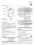
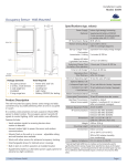
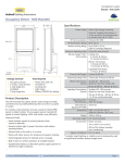
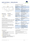
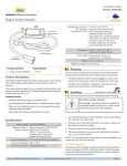
Installation Guide
Models: WIS-KCS
Hubbell Building Automation
Key Card Switch
Dimensions
0.43”
11mm
Weight
Environment
4.72”
120mm
Agency Compliance
4.72” H x 3.81” W x .43” D (at edge)
(120 mm x 97 mm x 11 mm)
3.5 oz. (99 g)
• Indoor use only
• 32° to 131°F (0° to 55°C)
• 5% to 95% relative humidity
(non-condensing)
FCC, IC
Planning
Take a moment to prepare and ensure optimal communications
with other system components, and for user convenience.
3.81”
97mm
Package Contents
Tools Required
▪ Key Card Switch
▪ Trim plate
▪ 2 screws, 2 wall anchors
▪ Power drill, 3/16” bit
▪ Screwdriver
▪ Leveling tool
▪ Pick a location near the door where occupants enter and exit
using the key card. A common location is on the wall opposite the door hinges, 3 ft. (92 cm) from the door jamb
▪ Consider the construction materials in the space and obstacles that may interfere with RF signals
Product Description
The Key Card Switch saves energy by signally HVAC, lighting,
and electrical loads that a room is unoccupied. It communicates
wirelessly with compatible devices in a guest room when a key
card is inserted or removed from the slot.
The Key Card Switch can be mounted on most surfaces using
the mounting plate or over an existing wall box.
Features Include:
▪ Determines occupancy based on guest room key card being
inserted or removed
▪ Harvests kinetic energy from the card action — no batteries
▪ Installs easily in new or existing rooms — no wiring
▪ Transmits room occupancy status wirelessly to other energy
saving devices in the room
▪ Enables other devices to minimize energy use whenever the
room is unoccupied
Specifications
Power Supply
Mechanical energy harvesting
(power is generated by the motion of
key card moving in and out)
Transmission Range
80 ft. (25 m)
RF Communications
EnOcean 902 MHz
EEP (EnOcean
Equipment Profile)
Card Slot Size
(Hotel Standard)
F6-04-01
4.72” H x 3.8” W x 0.43” D (at edge)
(120mm x 97mm x 11mm)
© 2013 Hubbell Building Automation
Installing
estimated time: 10 minutes
1. Decide where you want to mount the key card switch.
The ideal height is in line with wall switches (49” or 125 cm
on center) for comfortable access.
NOTE: If installing over an existing
wall box make sure any bare
electrical wires are capped.
2. Remove the trim plate from the
key card assembly.
3. Using a level and a pencil, lightly
mark two small dots to align the
upper edge of the key card switch.
4. Mount the key card switch securely to the wall using the
provided screws and wall anchors.
A. Using the pencil marks to
ensure it’s level, mark the two
mounting screw drill points.
B. Drill two holes for the wall anchors with a 3/16” drill bit and
insert the wall anchors.
d
C. Insert the top screw loosely and
level the Key Card Switch.
D. Insert the bottom screw, and
then hand tighten the top
screw.
| www.hubbell-automation.com
Page 1
Key Card Switch • Installation Guide
5. Insert the trim plate tabs into the
bottom slots of the key card
switch, and then lightly flex the
trim plate to insert the top tabs.
Linked to a Load Controller
▪ Insert key card: a wireless message is sent to close the cir-
cuits and turn on all linked loads, according to user-defined
program settings.
▪ Remove key card: a wireless message is sent to open the
TIP: To remove the trim plate
without marking it, press down
with a fingernail in the top groove
to ease the tabs out of the slots.
circuits and turn off all linked loads.
NOTE: For multiple installations, e.g., front and back doors, all
key cards must be removed to send a message.
6. Insert a key card to test the mechanism.
Troubleshooting
TIP: There should be an audible
click each time the key card is
inserted or removed.
Problem
Linking
Two or more compatible devices can be linked and configured
to provide the desired control. There are two basic types of
devices in the system; transmitters and transceivers.
▪ Transmit-only: Transmitters are simple energy-harvesting
devices that send RF messages to communicate a condition,
level, or state. Transmitters can only be linked to transceivers.
Examples > Self-powered Light Switches, Occupancy Sensors
▪ Transmit & Receive: Transceivers are controlling devices
that send as well as receive RF messages. They also process
relevant control logic, and actuate the appropriate outputs
(switching a light on or off for example). Transceivers can be
linked with transmitters as well as other transceivers. A transceiver can have up to 30 devices linked to it.
Examples > Relays, Gateways
The Key Card Switch is a Transmit-only Devices.
To link the Key Card Switch to a transceiver; the transceiver must
first be powered, within wireless range of the sensor, and set to
accepts links.
Solution Checklist
The key card switch
does not generate a
message
▪
The linked device
does not respond
to wireless messages
▪
▪
▪
902 MHz:
▪
▪
Verify there is an audible click when card is
inserted or removed
Verify slot is clear of foreign material or debris.
Use forced air to clean
Check for environment or range issues
Verify the device is linked
Check the transceiver connection and the wiring for errors
Check if appropriate devices are linked according to good system planning
FCC: SZV-PTM33XU
IC: 5713A-PTM33XU
This device complies with part 15 of the FCC rules and Industry Canada ICES-003. Operation
is subject to the following two conditions: (1) This device may not cause harmful interference,
and (2) this device must accept any interference received, including interference that may cause
undesired operation.
IMPORTANT! Any changes or modifications not expressly approved by the party responsible for
compliance could void the user’s authority to operate this equipment.
Le présent appareil est conforme aux CNR d’Industrie Canada applicables aux appareils radio
exempts de licence. L’exploitation est autorisée aux deux conditions suivantes: (1) l’appareil ne doit
pas produire de brouillage, et (2) l’utilisateur de l’appareil doit accepter tout brouillage radioélectrique subi, meme si le brouillage est susceptible d’en compromettre le fonctionnement.
IMPORTANT! Tous les changements ou modifications pas expressément approuvés par la partie
responsable de la conformité ont pu vider l’autorité de l’utilisateur pour actioner cet équipment.
Limited Warranty
ONE YEAR
To Link or Unlink a Key Card Switch
1. Set the desired transceiver to the
desired Link/Unlink mode. (refer
to receiving device’s installation
guide).
2. Insert and remove a key card three
times quickly - there should be an
audible click each time.
••>The Key Card Switch is now
linked.
ansceiver/controller instal
Refer to the “Linking” section of the transceiver/controller
installation guides to verify the linking process.
Typical Interactions
The key card interaction depends on the type of transceiver it is
linked to, for example:
Linked to a Thermostat or HVAC Controller
▪ Insert key card: normal mode is activated.
▪ Remove key card: setback mode is activated.
© 2013 Hubbell Building Automation
|
www.hubbell-automation.com
Page 2