1
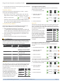
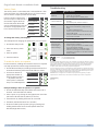
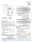
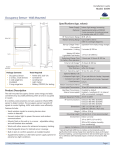
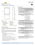
Installation Guide
Model: WIS-PSM
Hubbell Building Automation
Plug-In Switch Module
4.09”
104mm
1.85”
47mm
Set Button
Menu button
Interoperable Products /
EEPs (EnOcean
Equipment Profiles)
1.18”
30mm
Dimensions
3’ Cord to Plug End
Cord Lengths
1’ Cord to
Receptacle End
Weight
Agency Compliance
Package Contents
Tools Required
▪ Plug-in Switch Module
▪ None
Product Name (EEP #)
Rocker Pad Switch (F6-02-02)
Key Card Switch (F6-04-01)
Window handle (F6-10-00)
1BS Single Input Contact (D5-00-01)
Light Sensor, 0-1020 lux (A5-06-02)
Occupancy Sensor (A5-07-01)
Contact, single input (A5-30-01)
Central Gateway (A5-38-08)
4.09” L x 1.85” W x 1.26” D
(104 mm x 47 mm x 32 mm)
Plug cord: 3 ft. (91.4 cm)
Outlet cord: 1 ft. (30.5 cm)
12.3 oz. (348 g)
ETL, FCC, IC
Planning
Take a moment to plan for the module’s successful operation
and optimal communication with other system components.
Product Description
The Plug-In Switch Module provides an easy way to save energy
and control lighting and appliance loads based on room occupancy.
The module simply plugs into any standard wall receptacle and
receives wireless signals from EnOcean-based products that tell
it when to power on or off.
Features Include:
▪ Consider where the device will be plugged in, what it will
control, and how power cords can be kept out of the way
▪ Consider the construction materials in the space and obstacles that may interfere with RF signals
Installing
estimated time: 20 minutes
Read and understand instructions completely before starting.
▪ Provides switching of plug-in electrical loads
▪ Communicates with other devices to enable energy savings
▪ Plugs into any standard outlet, no wiring required (optional
ELECTRICAL SHOCK HAZARD
High Voltage. This device must be installed by
a qualified installer or electrician. Follow all applicable electrical codes for installation.
mounting plate provided)
▪ Easily links with wireless rocker pads or sensors
1. Turn the electrical load on (for example, a lamp) and unplug
the cord from the wall outlet.
Specifications
Power Supply
120 VAC, 50/60 Hz
Maximum Load or
Contact Ratings
General purpose: 15 A@ 120 VAC
Resistive: 15 A 120 VAC
Motor: ½ HP @ 120 VAC
Tungsten: 960 W @120 VAC
Ballast: 600 W @ 120 VAC
Power Consumption
1.1 W full load, 500 mW quiescent
Transmission Range
80 ft. (25 m)
RF Communications
EnOcean 902 MHz
© 2013 Hubbell Building Automation
|
2. Plug the cord of the electrical load, for example a lamp, into
the outlet cord of the module.
3. Plug the module into a standard wall outlet.
4. Test the connection by actuating the load using the Set but) on the module
ton (
NOTE: The plug and outlet are polarized, and not intended to be
mated with non-polarized devices.
Optional Mounting
The Plug-In Switch Module provides a fixed mounting option to
prevent damage and theft. Using the included mounting plate,
mount the device high enough off the floor to avoid spills and
impact with cleaning equipment.
www.hubbell-automation.com
Page 1
Plug-in Switch Module • Installation Guide
1. Using a level and a pencil, lightly mark two small dots to
align the upper edge of the module on the wall where you
want to mount it.
TIP: For easy housekeeping, provide sufficient clearance for
vacuum cleaners.
2. Slide the mounting plate off the
back of the module.
About the Setup Interface
The setup interface has two buttons, Menu and Set, that each
have a corresponding 3-color LED (green, amber, red). This simple interface is used to link and configure devices as a system.
The buttons and LEDs are used to navigate and select linking
and setup options through a 3-tier menu system consisting of
different Modes > Menus > Options.
To use the interface, hold the module so both thumbs can click
the buttons without obscuring the LEDs. The illustration and
legend below describe how the buttons are used and the meaning of the LED responses.
3. With the tab lock side down,
mount the plate securely to the
wall.
A. Using the pencil marks to enunting
i screw
crew
rew
ew d
drill
rill
ill poi
p
ints.
sure it’s level, mark the two mounting
points.
To exit from anywhere in a menu, hold both buttons at the same
time for 2 seconds.
ho
ors with
h a 3/16” d
drill
rill bit
ri
ril
rill
B. Drill two holes for the wall anchors
and insert the wall anchors.
C. Insert the first screw loosely
and level the module.
D. Insert the second screw, and
then hand tighten the first
screw.
4. Slide module onto the mounting
plate until it clicks in place.
NOTE: Any EnOcean-based switch
can be linked to the module.
The Menu LED or Set LED display solid for a number of seconds in a certain color to indicate a mode or a confirmation.
The Menu LED blinks a number of times in a color to indicate a selected menu.
The Set LED blinks a number of times in a color to indicate
an option.
Linking
Two or more compatible devices can be linked and configured
to provide the desired control. There are two basic types of
devices in the system; transmitters and transceivers.
A number in a white box indicates the number of times to
click the Menu button or Set button.
A number in a black box indicates the number of seconds to
hold down the Menu button or Set button.
▪ Transmit-only: Transmitters are simple energy-harvesting
devices that send RF messages to communicate a condition,
level, or state. Transmitters can only be linked to transceivers.
Examples > Self-powered Light Switches, Occupancy Sensors
▪ Transmit & Receive: Transceivers are controlling devices
that send as well as receive RF messages. They also process
relevant control logic, and actuate the appropriate outputs
(switching a light on or off for example). Transceivers can be
linked with transmitters as well as other transceivers. A transceiver can have up to 30 devices linked to it.
Examples > Relays, Gateways
The Plug-In Switch Module is a Transceiver
(transmits & receives)
To link the occupancy sensor to a transceiver; the transceiver
must first be powered, within wireless range of the controls it is
to be linked to, and set to accepts links.
To link a transmitter to a transceiver
1. Access Basic Setup mode.
NOTE: By default, the Accept Link option in the Linking
menu is selected. Once activated, this option stays active for
two minutes to provide time to link multiple devices.
Ready to accept links.
2. For the transmitter to be linked, do one of the following according to the type of device:
A. Sensor: click the designated link button.
B. Key Card Switch: insert/remove the card 3 times quickly.
C. Rocker Pad: click the top button 3 times quickly.
Next, the desired transmitter, or another transceiver, is triggered
to send a special link message. The awaiting transceiver receives
and stores the link permanently so the devices can interact to
provide a variety of intelligent control options.
Device linked successfully.
Set LED displays solid
green for 3 seconds.
Ready to accept new links.
© 2013 Hubbell Building Automation
|
www.hubbell-automation.com
Page 2
Plug-in Switch Module • Installation Guide
3. To exit mode and return to normal operation, press and hold
both buttons for 2 seconds.
To change the auto-on option:
To unlink a device
This example shows changing the option from Automatically
Determined to Disabled.
Follow the same steps as described in the “To link...” section
above with the following deviations:
▪ After step 1 in the “To link...” section above, click the “Set”
(right) button 3 times to enable the “Remove Link” option.
2. Select the Switched
Auto-On menu.
Ready to remove links.
1. Access Basic Setup mode.
3. Select an option.
▪ Follow the same instructions as shown in Step 2 of the “To
link...” section. The Set (right) LED will turn red briefly to indicate the link was successfully removed.
To restore factory defaults
Follow these steps to clear all linked devices and restore the
Plug-in Switch Module to its factory default settings.
1. Press and hold both buttons for 15 seconds
>> Hold buttons until the Menu (left) LED is solid RED and
the Set (right) LED is solid Amber (Both LEDs will turn various
colors as the module cycles through the resetting process.
2. Press and hold the Set (right) button for 3 seconds to confirm factory reset.
3. Device will reboot and initiate start up LED sequence.
Configuring
The default settings on the module support common control
scenarios. However, some occupancy settings can be adjusted
on the module using the setup interface, if required.
Setting
Default
Auto-On
Automatically If linked to an occupancy senDetermined
sor, the default is Enabled.
Application
If linked to a switch, the default
is Disabled for manual control.
4. Save the selection.
Auto-Off
There are two auto-off menus, one for occupancy sensors, and
one for rocker switches. For linked occupancy sensors, the default is 15 minutes. For linked rocker pads and key card switches,
the default is Disabled to allow
manual control.
Option
Clicks Blinks
From the auto-off timer menu,
the active option is indicated
by the number of green blinks
on the “Set” LED; amber blinks
indicate an unsaved change.
Click the Set button an appropriate number of times to select
an option.
Disabled
If linked to a rocker pad or key
card switch.
3. Select an option.
Motion Auto-Off
15 minutes
If linked to occupancy sensor.
4. Save the selection.
If linked to a key card switch.
Auto-On
The default Auto-On option is automatically determined based
on the type of device that is linked. Auto-On is Disabled if the
first linked device is a switch, or Enabled if the device is an
occupancy sensor.
From the Auto-On menu, the active option is indicated by the
number of green blinks on the
“Set” LED; amber blinks indicate
an unsaved change. Click the “Set”
button an appropriate number
of times to select an option.
Option
Clicks Blinks
Disabled
60 mins.
2. Select the Switched
Auto-Off menu.
Switched Auto-Off
If linked to occupancy sensor.
30 mins.
1. Access Basic Setup mode.
If linked to a occupancy senor
and a door sensor.
30 seconds
15 mins.
This example shows changing the option from Disabled to 5
minutes.
5 minutes
Egress
5 mins.
To change the switched auto-off option:
Vacancy Check
Door/Window Ajar 2 minutes
Disabled
To change the motion auto-off option:
This example shows changing the option from 15 to 5 minutes.
1. Access Basic Setup mode.
2. Select the Motion
Auto-Off menu.
3. Select an option.
4. Save the selection.
Enabled
Automatically
Determined
© 2013 Hubbell Building Automation
|
www.hubbell-automation.com
Page 3
Plug-in Switch Module • Installation Guide
Troubleshooting
Vacancy Check
The vacancy check is a time delay that is activated when a door
opens and closes. The linked loads will turn off, if the sensor(s)
do not confirm occupancy within the time delay.
From the Vacancy Check menu,
Option
the active option is indicated by
5 mins. (default)
the number of green blinks on
the Set LED; amber blinks indi15 minutes
cate an unsaved change. Click the
Set button an appropriate num- 30 minutes
ber of times to select an option.
Clicks Blinks
Problem
The device does not
control linked load
Cannot link other
devices
▪
▪
▪
▪
▪
▪
▪
60 minutes
▪
▪
120 minutes
▪
To change the vacancy check option:
This example shows changing the option from 5 to 15 minutes.
1. Access Basic Setup mode.
2. Select the Vacancy Check
menu.
Cannot change settings on the device
The device does not
respond to wireless messages or
selected settings
3. Select an option.
4. Save the selection.
Contains:
To enable the device as a repeater
In some situations, enabling the transceiver device as a repeater
can help optimize the wireless range between devices.
1. Access Advanced Setup by holding both buttons down for 5
seconds and releasing them when both LEDs turn amber.
2. Click the Set button an
appropriate number of
times to select an option.
>> By default, the first
menu option in advanced
setup is to Enable Repeater.
Solution Checklist
The device does not
power up
Option
Clicks Blinks
Disabled (default)
1 Hop
▪
▪
▪
▪
▪
▪
Check the wiring for errors
Check the circuit breaker
Use a voltage meter to confirm power
Click the Set button to open/close the relay
manually
Turn off the power and then restore it
Check if Accept Link option can be accessed
Move closer to the device; it may be out of
range
Try linking a different device
Check for environmental conditions that interfere with RF signals
Verify the maximum number of devices (30)
has not been exceeded
Check if menu item can be accessed
Check if changes can be saved
Check for environment or range issues
Verify the device is linked
Check if appropriate devices are linked according to good system planning
Extend the antenna to amplify the range:
remove it from the groove in the module,
straighten it and slide it into the white antenna
sleeve provided
FCC: SZV-STM300U (902 MHz)
IC: 5713A-STM300U (902 MHz)
This device complies with part 15 of the FCC rules and Industry Canada ICES-003. Operation is subject
to the following two conditions: (1) This device may not cause harmful interference, and (2) this device
must accept any interference received, including interference that may cause undesired operation.
IMPORTANT! Any changes or modifications not expressly approved by the party responsible for
compliance could void the user’s authority to operate this equipment.
Le présent appareil est conforme aux CNR d’Industrie Canada applicables aux appareils radio exempts
de licence. L’exploitation est autorisée aux deux conditions suivantes: (1) l’appareil ne doit pas produire
de brouillage, et (2) l’utilisateur de l’appareil doit accepter tout brouillage radioélectrique subi, meme
si le brouillage est susceptible d’en compromettre le fonctionnement.
IMPORTANT! Tous les changements ou modifications pas expressément approuvés par la partie
responsable de la conformité ont pu vider l’autorité de l’utilisateur pour actioner cet équipment.
Limited Warranty
ONE YEAR
2 Hops
Example: Setting a device to operate as a repeater.
1. Access the Advanced setup (hold down both buttons for 5
seconds - until both LEDs turn amber).
2. Select “option 2” by clicking the Set (right) button two times.
(Set button LED will blink 2x (amber) to confirm)
3. Save selection by holding Set button for 2 seconds.
4. Exit Menu (hold both buttons for 2 seconds.)
5. Re-boot module by either power cycling or pressing and
holding both buttons for 10 seconds (release when Left
LED=Red, Right LED=Green).
© 2013 Hubbell Building Automation
|
www.hubbell-automation.com
Page 4