1
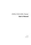
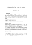
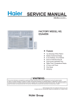
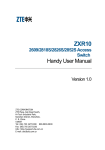
Contents
02
02
02
03
05
05
05
05
06
06
06
06
08
08
08
08
09
09
09
11
11
12
12
12
12
13
13
13
13
14
14
14
14
15
15
ARP Attack Troubleshooting
Malfunction Situation
Malfunction Analysis
Solutions
Switch Port Self-loop
Malfunction Situation
Malfunction Analysis
Solution
ARP Binding
Network Topology
Malfunction Situation
Solutions
RSTP Function
Building Network Demand
Network Topology
Solution Selection
Solution Implementation
Test Results
Background Knowledge
ACL Configuration
Background Knowledge
Case 1
Malfunction Situation
Malfunction Analysis
Solution
Case 2
Malfunction Situation
Malfunction Analysis
Solutions
Case 3
Malfunction Situation
Malfunction Analysis
Solutions
Multicast Service
Multicasting
15 Equipment and Software
15 Network Topology
16 Test
19 Link Aggregation
19 Background Knowledge
19 Case 1
19 Malfunction Situation
19 Malfunction Analysis
20 Solution
21 Case 2
21 Malfunction Situation
21 Malfunction Analysis
22 Solution
23 802.1x Maintenance Experience
23 Background Knowledge
23 Case 1
23 Network Topology
24 Malfunction Situation
24 Malfunction Analysis
24 Solution
24 Case 2
24 Network Topology
24 Malfunction Situation
24 Malfunction Analysis
25 Solution
26 DHCP Troubleshooting
26 DHCP
26 Malfunction Situation
26 Network Topology
27 Malfunction Analysis
27 Solutions
28 Implementation
29 Lower-End Switch Configuration
29 Preparation
31 Configuration and Reference Command
August 2007
Issue 54
ARP Attack
Troubleshooting
⊙ Wang Tujian, ZTE Corporation
Malfunction Situation
piece of alarm information: too many ARP broadcast
Network center fails to connect to eleven
packets are received at gei_2/4 interface. Use
ZXR10 2826 access routers in a student
relative command to show traffic information on the
dormitory. 40% users are unable to get
port.
online.
Result: It is found that 100,000 broadcast
packets are added in every 10 seconds.
Malfunction Analysis
Analysis 1
During Network Management System
Analyze the access switch 2826 at gei_2/4
interface. It gives the following causes.
(NMS) analysis, it is found that 11 switches
There is a loop at the user side.
are virtually disconnected and cannot
User host is toxic and sends broadcast packets
be successfully pinged from the central
equipment room.
Log on to a switch through Hyper
Terminal. An IP address of the switch
continuously.
User installed ARP attack software on host. The
host sends broadcast packets continuously.
Result: It is found that 2826 switch has
is 172.168.0.123. It is found that CPU
172.168.0.111 IP address at gei_2/4 interface.
utilization ratio is 93%-100%. Observe the
Analysis 4
alarm and configuration information.
Result: No abnormity is found.
Analysis 2
Connect to T40G switch in an
assembling layer. It is found that there is a
02
Analysis 3
Maintenance Experience
Connect to the switch again. Break the packets
and analyze them.
Result: It is found that there is a host that is
sending broadcast packets continuously. MAC
address of that host is 00:19:e0:a9:5a: fc.
www.zte.com.cn
Analysis 5
Find the detailed position of the host according
arp –s <gateway IP> <gateway MAC>
command.
Example: arp –s 218.197.192.254
to the label. The host is online. Get the host offline.
Result: All ZXR10 2826 switches are now
00-01-02-03-04-05
After binding, use arp –a command to
working in a normal way. CPU utilization ratio is
below 5%.
view ARP buffer:
C:\Documents and Settings>arp –a
Solutions
Interface: 218.197.192.1 --- 0x2
ARP virus is a popular and easy-burst virus. It
Internet Address Physical Address Type:
caused the following problem in the network: A host
218.197.192.254 00-01-02-03-04-05
was on-line in normal conditions, but all of a sudden
static
it gets off-line and it can not ping its gateway now.
Now the type is static. Manual binding is
Reboot the host and run command arp –d in MS-
disabled when host is turned off. When host
DOS mode. Now the host is on-line for a while.
is turned on , it is necessary to perform the
To solve the problem that is caused by ARP
virus, use the following procedures:
binding again.
●
Find out the toxic host and clear the
Bind ARP to PC statically.
virus. It is advised to install special tool
Note: It is not suitable for large networks.
on hosts in the whole network.
1. When the host is on-line, enter into MS-DOS
1. Use arp –a command after ARP
mode and input arp –a command to observe the
attack, as a result it is found that gateway
correct MAC address that corresponds to a gateway
MAC is replaced by an attacked host MAC.
IP address. Now record the MAC address When PC
consider it as 00-01-06-07-08-09.
●
gets failed to get on-line then run arp –d command
C:\Documents and Settings>arp –a
to delete contents in ARP buffer to recover the PC
Interface: 218.197.192.1 --- 0x2
temporarily. Once the PC gets online, get it offline
Internet Address Physical Address Type:
and then run arp –a command.
218.197.192.254 00-01-06-07-08-09
Example: suppose gateway address of a host is
218.197.192.254. Host IP address is 218.197.192.1.
When host is online in normal condition then run arp
–a command that shows the following output:
dynamic
Record this MAC address for further
solution.
With the recorded MAC address, use
C:\Documents and Settings>arp –a
show mac command to find the port
Interface: 218.197.192.1 --- 0x2
through which the toxic host accesses.
Internet Address Physical Address Type
Consider that the toxic host is connected
218.197.192.254 00-01-02-03-04-05 dynamic
with T64 switch. Use show mac command.
00-01-02-03-04-05 is the MAC address of
It gives the output, as shown in Figure 1.
gateway. It has a dynamic type, so it is possible to
Isolate the toxic host and clear the ARP
change its type.
virus.
2. When host can not get online in normal way,
bind IP gateway MAC manually. To bind them, run
Data Products
03
August 2007
Issue 54
ZXR10(config)#show mac
Total mac address : 6
Flags:vid –-VLAN id,stc—static,per—-permanent,toS—-to—-static,
srF -–source filter,dsF -–destination filter,time -–day:hour:min:sec
Frm -–mac from where:0,drv;1,config;2,VPN;3,802.1X;4,micro;5,dhcp
MAC_Address port
vid static locked src_filter dst_filter
-------------------------------------------------------------------------------------------0001.0607.0809 fei_8/6
0000.0000.2222
200 0
1
1
0
1
0
1
0
0
0000.0000.0022 fei_8/14 888
0
0
0
0
0000.0000.1111 gei_3/3 888
1
0
0
0
0000.0000.3333 gei_3/3 888
1
1
0
0
0000.0000.0021 fei_8/12 888
0
0
0
0
-----------------------------------------------------------------ZXR10(config)#
Figure 1. The output of the command
2. Install special tool on hosts in the whole network, such as ARP fire-wall.
04
Maintenance Experience
www.zte.com.cn
Switch Port Self-loop
⊙ Tu Yong, ZTE Corporation
Malfunction Situation
An organization uses a ZXR10 3928 switch to
ZXR10(cfg)#loop-detect interface
connect the private line network centers. Switch was
working normally until several new private lines are
added. Newly added private lines have not started
ii. Set the vlan in which loop detection is
enabled.
to perform their functions. But CPU utilization ratio
of ZXR10 3928 switch is still high, and the primary
services are interrupted.
Malfunction Analysis
Observe the equipment. It is found that the
ZXR10(cfg)#loop-detect interface
<port-name> vlan <vlan-id> enable
iii. Enable loop-detect protection
function.
switch MAC address is continuously drifting.
After close observation, it is found that the switch
is connected to network centers through fiber
ZXR10(cfg)#loop-detect protectinterface <port-name> [enable|disable]
transceiver. As the transceiver has no user as yet, it
loops receiving and sending. Port self-loop occurs
that causes a problem.
If loop-detect protect-interface <portname> enable command is configured
on switch then a switch does not take any
Solution
To solve this problem, perform the following
steps:
measure after an alarm is sent. If loopdetect protect-interface <port-name>
disable command is configured then
1. Close the transceiver that has no user.
a switch closes a port during the loop
2. Use a port self-loop detection function on the
occurrence. A loop-detection protection
switch to find out on which port self-loop occurs.
Perform the following steps to use port self-loop
detection function on switch:
function is enabled in this case.
Note: By default, a loop-detection
protection function is disable.
i. Enable self-loop detection function on a port or
multi ports.
Data Products
05
August 2007
Issue 54
ARP Binding
⊙ Yang Yong, ZTE Corporation
Network Topology
Enable NAT on GAR router to provide public network addresses for internal PCs, as shown in
Figure 1. Internal network IP address on GAR is 192.168.2.2. Vlan1 IP address on ZXR10 3906 is
192.168.2.1. All users are in Vlan1 and have fixed IP, and their gateway address is 192.168.2.1.
Figure 1. Network Topology of ARP Binding
Malfunction Situation
There are two malfunctions:
●
Some users are unable to get online and are unable to ping successfully to gateway.
●
Bind an internal network IP to a MAC address to prevent a user to set an IP at random. But
binding is not effective in this case.
Solutions
Malfunction 1
Log on to GAR and 3906 to check ARP tables. It is found that there are some items that have the
age as TS, as shown in the following content.
Address
Age(min)
Hardware Addr
Interface
fei_0/1
192.168.2.70
TS
0090.f547.8112
192.168.2.157
TS
0015.c577.2b98
fei_0/1
192.168.2.35
TS
0020.eda8.67fd
fei_0/1
It indicates that the users who have the IP addresses are with TS and are not able to get online.
MAC addresses of these users do not correspond to the PC MAC addresses.
There are two types of ARP table binding: static and permanent. Ages of the two types are
defined as S and P respectively. These items can not be deleted with command clear arp.
When searching related ARP commands on GAR and 3906 L3 interfaces, it is found that there
are two types of ARP static bindings: dynamic and manual. Manual binding is to use set static
command to bind MAC and IP. Use show run command to view the result, such as set arp static
06
Maintenance Experience
www.zte.com.cn
192.168.2.185 0016.ec3f.73c3. Dynamic binding is to use arp to-static command to bind IP in an
ARP table to MAC in an automatic way. A result can not be viewed with show run command.
Note: In an ARP table, TS is referred as “To Static”.
Use clear arp static command on GAR and 3906 L3 interfaces to clear the static binding. Use
show arp command to view ARP table, and there are no items with TS. Now the users can get
online.
Malfunction 2
IP and MAC addresses are bonded on ZXR10 3906 Vlan1 interface, as shown in the following
content.
set arp permanent 192.168.2.185 0016.ec3f.73c3
set arp permanent 192.168.2.173 0015.5820.ba3d
set arp permanent 192.168.2.218 0016.ec3f.689d
After performing the tests, it is found that the binding is not effective. User that has a MAC
address such as 0016.ec3f.73c3 can use IP 192.168.2.173 to get online.
After checking the configuration, it is found that there is no problem. Use show arp command to
view ARP table, it is shown that the internal user IP Age is set as P.
Use show ip traffic command. Result shows that there are many ICMP redirect packets on
ZXR10 3906 switch. Check the network topology again. Result shows that an internal PC gateway
is 192.168.2.2 on internal interface of GAR router, although it is configured as 192.168.2.1 on Vlan1
interface of 3906 switch. There is L2 forwarding but not L3 transmission. ARP binding should be
performed on an internal interface of GAR router instead of 3906 switch vlan1 interface.
Use clear arp permanent command on 3906 switch vlan1 interface to clear ARP bindings, and
then configure bindings on an internal interface of GAR router:
set arp permanent 192.168.2.185 0016.ec3f.73c3
set arp permanent 192.168.2.173 0015.5820.ba3d
set arp permanent 192.168.2.218 0016.ec3f.689d
If an IP address is set as 192.168.2.173 on PC that has a MAC address such as 0016.ec3f.73c3,
then the PC can not ping a gateway.
If a PC IP is set to an address that has no binding IP, such as 192.168.2.254 then the PC can
ping a gateway. It is due to a fact that a GAR allows a MAC in ARP table to bind it to IPs, as shown in
the following content.
Address
Age(min)
Hardware Addr
Interface
192.168.2.185
P
0016.ec3f.73c3
fei_0/1
192.168.2.254
2
0016.ec3f.73c3
fei_0/1
To prevent this problem, make a spoofing binding to idle IP addresses.
Example: Use the following command:
set arp permanent 192.168.2.254 0000.0000.0000.
Note: Set internal PC gateway to 192.168.2.2.
Data Products
07
August 2007
Issue 54
RSTP Function
⊙ Yang Yong, ZTE Corporation
Building Network Demand
Solution Selection
There is SS heartbeat detection in
As the four switches are connected in such a
two NGN rooms that requires two ZXR10
way that they form a loop, it is necessary to enable
2826S switches in each room. SS primary
STP to prevent logical loop. ZXR10 2826S switch
heartbeat line connects to one switch, and
supports three types of STPs:
backup heartbeat line connects to the other
●
STP
switch. This is for equipment and links
●
RSTP
redundancies and it avoids signal-point
●
MSTP
malfunction.
Convergence speed of 802.1d STP is slow (50s).
As the network topology is simple and there is no
Network Topology
Use NO.24 electrical ports to connect
Vlan, it is not necessary to use MSTP. In this case
RSTP is suitable.
the switches in the same room and use
ZXR10 2826S switch also supports STR reply.
NO.25 optical ports to connect the switches
STR reply makes the switch that does not allow STP
in different rooms, as shown in Figure 1.
to forward BPDU packets.
There are two solutions:
SS heartbeat line is connected to NO.1
electrical port on each switch.
●
Enable RSTP on one switch, and enable STP
relay on the other three switches.
●
Enable RSTP on the four switches.
If RSTP is enabled on 2826S-1 and STP reply
is enabled on the other three switches then the
NO.25 port on 2826S-1 has a discard status. NO.24
port is in forwarding status in this case. Data flow
from 2826S-1 to 2826S-3 is 2826S-1→2826S-2→
2826S-4→2826S-3.
After performing the tests, it is found that the
convergence speed is not good (15s). So use the
second solution.
Figure 1. RSTP Topology
08
Maintenance Experience
www.zte.com.cn
Solution Implementation
For network structure preciseness and
maintenance convenience, set each bridge PRI
manually to designate a root bridge.
2826S-1 PRI is 4069, 2826S-2 PRI is 4096*3,
2826S-3 PRI is 4096*2, and 2826S-4 PRI is 4096*4.
Therefore 2826S-1 in Room A is selected as a root
bridge in the network, as shown in Figure 2. NO.24
and NO.25 ports on 2826S-1 are the designated
ports for their own segments.
According to STP working principle, NO.25
port on 2826S-4 is in discard status. It discards the
frames and does not learn MAC address, so there is
no loop in this network.
ZXR10 2826S switch supports edge-port
function. Edge-port does not take part in STP. Its
status can be from discarded state to a forwarding
state. Other ports have 30s time delay for status
transformation from a discarded state to a learning
Figure 2. RSTP Implementation
Test Results
Connect a PC to a port on a switch.
Set the PC IP to 172.16.0.x/24 and ping
the management addresses of the four
switches. Then perform the following tests:
state and then to a forwarding state. Set the ports as
●
Turn off the switch.
edge-ports except NO.24 and NO. 25 ports on each
●
Turn down the links between switches in
different rooms.
switch to increase the convergence speed.
Configuration is shown in the following content.
set stp enable
set stp forceversion rstp
set stp instance 0 bridgeprio <0-61440>
set stp edge-port add port 1-23
set ipport 0 ipaddress 172.16.0.x
255.255.255.0
set ipport 0 vlan 1
●
Turn down the links between switches in
the same room.
Convergence time of these tests ranges
from 0s to 6s. It matches an expected
demand.
Background Knowledge
Spanning Tree Protocol (STP) is
applicable to a loop network. It blocks the
set ipport 0 enable
redundant paths via specific algorithm. It
Use show stp (show stp instance 0, show
topology. It is used to prevent the message
stpport <1-25>) and Ping commands to check
whether the switches and ports are consistent with
the description in Figure 2 or not.
changes a loop network into a loop-free tree
proliferation and endless cycling in a loop
network.
Bridge Protocol Data Unit (BPDU) is
used to send STP information between
bridges. There are two types of BPDU:
Data Products
09
August 2007
Issue 54
●
●
Configuration BPDU: It is sent by the
minimum accumulated path cost to root bridge
root bridge every two seconds.
becomes the root port.
To p o l o g y C h a n g e N o t i f i c a t i o n
BPDU(TCN BPDU): It is sent to upriver
3. Select a designated port: A port with the
minimum path cost becomes the designated port.
a root bridge by the switch that finds a
4. Set the redundant switch port as a discard
topology change.
port to avoid loop in topology network.
STP performs the following steps to
Port status is shown in Table 1.
create a loop-free logical topology:
STP timers are shown in Table 2.
1. Root bridge selection: A switch with
ZXR10 2826S STP module supports three
the lowest bridge ID becomes the root
modes that include SSTP, RSTP and MSTP. These
bridge. A Bridge ID consists of bridge PRI
modes comply with IEEE802.1d, IEEE802.1w and
and MAC address. By default, bridge PRI is
IEEE802.1s respectively.
32768.
●
2. Select a root port: A port with the
SSTP (Single Spanning Tree Protocol) fully
complies with IEEE802.1d in functionality.
A bridge that is running STTP mode can be
Table 1. Port Status
interconnected with RSTP and MSTP bridges.
Status
Action
Blocking
All ports are in this status when switch starts. In
this status, a port does not forwarding frames. It
detects BPDUs to prevent loop.
higher convergence speed than an STP
In this status, a port detects BPDUs to judge
whether there is a loop before forwarding
frames.
switch port is transferred (From Discarded to
Listening
Learning
Forwarding
●
In this status, a port detects BPDUs and learns
all paths and MAC tables. It does not forwards
frames.
In this status, a port forwards and receives
frames.
RSTP (Rapid Spanning Tree Protocol) provides
(i.e. SSTP mode). When a network topology
changes, then the status of old redundant
Forwarded) quickly in the case of point-to-point
connection.
●
Concepts of instance and VLAN mirroring
are added in MSTP (Multiple Spanning Tree
Protocol). SSTP and RSTP mode are considered
to be MSTP mode instances. Only one instance
0 exists is an example. MSTP mode also
provides fast convergence and load balance in
Disable
In this status, a port does not take part in STP or
forward frames. It is administratively closed.
VLAN environment.
In SSTP and RSTP modes, there is no VLAN
concept. There is only one status for each port that
is a forwarding status. This status is consistent
Table 2. STP Timers
in different VLANs. But in MSTP mode, there are
Timer
Definition
Interval
Forward Delay
The time for learning and listening.
30s
Max Age
The time for storage BPDU.
20s
10
Maintenance Experience
multiple spanning tree instances. Forwarding
statuses of ports are different in different VLANs.
Multiple independent sub-tree instances can be
formed inside MST region to achieve load balance.
www.zte.com.cn
ACL Configuration
⊙ Feng Chao,Gu Weiwei,Wei Hui, ZTE Corporation
Background Knowledge
●
Mixed ACL: Source/destination MAC
ACL is used to implement the data message
address, source VLAN ID, source/
filtering, policy routing and special flow control. An
destination IP address, TCP source/
ACL may contain one or more rules defined for
destination port number, UDP source/
special types of packets. These rules tell the switch
destination port number are matched
to allow or deny the access of packets that match
against the ACL.
the criteria specified in the rules.
●
matched against the ACL.
ZXR10 T160G/T64G/T40G provides seven
types of ACLs:
●
●
●
Basic IPv6 ACL: Source IPv6 address is
●
Extended IPv6 ACL: Source/destination
Basic ACL: Only source IP addresses are
IPv6 address is matched against the
matched against the ACL.
ACL.
Extended ACL: Source/destination IP address,
●
User-defined ACL: Number of VLAN
IP protocol type, TCP source/destination port
TAG and offset byte are matched against
number, UDP source/destination port number,
the ACL.
ICMP type, ICMP code, DiffServ Code Point
Each ACL has an ACL code for
(DSCP), ToS and precedence are matched
identification that is a digit. Code ranges of
against the ACL.
different ACLs are described in the following
Layer 2 ACL: Source/destination MAC address,
content.
source VLAN ID, Layer 2 Ethernet protocol type
●
Basic ACL: 1~99
and 802.1p priority value are matched against
●
Extended ACL: 100~199
the ACL.
●
Layer 2 ACL: 200~299
Data Products
11
August 2007
Issue 54
●
Mixed ACL: 300~349
●
Basic IPv6 ACL: 2000~2499
●
Extended IPv6 ACL: 2500~2999
●
User-defined ACL: 3000~3499
To configure ACL, follow these three
steps in order:
now, but the new users are failed.
Malfunction Analysis
Use show acl 101 command to view
configuration. Result is shown in the following
content.
1. Configure a time range.
2. Define an ACL.
acl extend num 101
3. Apply the ACL to physical ports.
rule 1 permit tcp 202.98.4.3 0.0.0.0 any eq telnet
rule 2 permit tcp 202.98.4.8 0.0.0.0 any eq telnet
Case 1
rule 3 permit tcp 202.98.4.3 0.0.0.0 any eq telnet
Malfunction Situation
rule 10 deny any any eq telnet
An ACL is applied on ZXR10 T64E
router L3 interface to limit users to telnet.
rule 4 permit tcp 218.37.5.3 0.0.0.0 any eq telnet
rule 11 permit ip any any
rule 5 permit tcp 219.38.5.3 0.0.0.0 any eq telnet
For example, allow the hosts in network
management room to telnet to log on ZXR10
Note: Rule 5 is after rule 11, not after rule 4.
T64E router and forbid other users.
A system executes the commands in an order.
ACL is defined as follows:
System executes rule 10 to forbid all users to
perform telnet. Rule 5 is after rule 10, so user with
acl extend num 101
rule 1 permit 202.98.4.3 0.0.0.0 any eq
telnet
rule 2 permit 202.98.4.8 0.0.0.0 any eq
telnet
IP 219.38.5.3 fails to perform telnet.
In an ACL, the number after rule is only an
identifier. It has nothing to do with the execution
order. System executes rules according to the rule
configuration order.
rule 3 permit 202.98.4.30 0.0.0.0 any eq
telnet
rule 4 permit 218.37.5.3 0.0.0.0 any eq
telnet
Solution
There are two ACLs:
ACL101:
rule 10 deny any any eq telnet
rule 11 permit ip any any
acl extend num 101
rule 1 permit tcp 202.98.4.3 0.0.0.0 any eq telnet
Fist four users are allowed to use telnet
and others are forbidden.
If a user with an IP 219.38.5.3 is
rule 3 permit tcp 202.98.4.3 0.0.0.0 any eq telnet
rule 4 permit tcp 218.37.5.3 0.0.0.0 any eq telnet
allowed to use telnet then add rule 5 permit
rule 10 deny tcp any any eq telnet
219.38.5.3 0.0.0.0 any eq telnet command
rule 11 permit ip any any
in acl 101.
rule 5 permit tcp 219.38.5.3 0.0.0.0 any eq telnet
First four users can perform the telnet
12
rule 2 permit tcp 202.98.4.8 0.0.0.0 any eq telnet
Maintenance Experience
www.zte.com.cn
ACL 102:
Malfunction Analysis
ACL rules allow only a part of IP
acl extend num 102
packets to get passed. ARP addresses
rule 1 permit tcp 202.98.4.3 0.0.0.0 any eq telnet
are aged after several minutes. When ping
rule 2 permit tcp 202.98.4.8 0.0.0.0 any eq telnet
is performed to check the other end then
rule 3 permit tcp 202.98.4.3 0.0.0.0 any eq telnet
the host sends an ARP requests. But ARP
rule 4 permit tcp 218.37.5.3 0.0.0.0 any eq telnet
packets are controlled, so host can not
rule 5 permit tcp 219.38.5.3 0.0.0.0 any eq telnet
ping successfully. As a result the service is
rule 10 deny tcp any any eq telnet
interrupted.
rule 11 permit ip any any
Results of the above mentioned ACLs are
Solutions
Add a rule x permit arp any any
different. ACL 101 allows the first four users to
command before the deny any command to
perform telnet. ACL 102 allows the first five users to
solve this problem.
perform telnet. So pay attention when adding ACL
rule items.
Case 2
Malfunction Situation
Define a L2 ACL on ZXR10 T64G switch. When
Note: When ACL is used to deny part of
flows then it is necessary to use permit any
any command at the end of rules. Otherwise
all flows are denied. By default, deny any
any command is added at the end of ACL,
although it is not possible to view it with
Show command.
the ACL is applied on port, service is interrupted.
L2 ACL is configured in the following way:
acl link number 201
rule 1 permit ip ingress 801 0011.110c.5140
0000.0000.0000 egress any
rule 2 permit ip ingress 801 0011.1149.cf96
0000.0000.0000 egress any
rule 3 permit ip ingress 801 0001.0292.308d
0000.0000.0000 egress any
rule 4 permit ip ingress 801 0008.74db.dadf
0000.0000.0000 egress any
rule 5 permit ip ingress 801 0013.2046.b309
0000.0000.0000 egress any
rule 6 deny any ingress any egress any
Data Products
13
August 2007
Issue 54
Malfunction Analysis
Integrated format of applying ACL is:
ip access-group <acl-number> <profilenumber> in
Profile-number is a required parameter. Its value
is 0 or 1. 0 means enabling protocol protection. 1
means disabling protocol protection. By default, the
value is 0.
Protocol protection is enabled to increase the
ICMP PRI by flow table. A flow table is before ACL.
ICMP belongs to the content of protocol protection,
so its PRI is bigger than ACL.
Configuration on ZXR10 3928 switch uses
Figure 1. Forbidding Pinging
Case 3
Malfunction Situation
Enable L2 transparent transmission
a default value of profile-number. So ACL is not
effective. Now the PC can ping a server.
Solutions
Change the switch configuration as shown in the
following content.
on ZXR10 3928 switch, as shown in
Figure 1. Even after applying deny
acl extend number 101
icmp command, the PC can still ping
rule 1 deny icmp 10.40.184.0 0.0.3.255 any
the server.
rule 2 permit ip any any
Use protocol-protect mode icmp
disable command to disable ICMP
int fei_1/1
protection function on the port where
protpcol-protect mode icmp disable
ACL is applied. But it fails.
switchport access vlan 1
Configuration of ZXR10 3928 is
shown in the following content.
acl extend number 101
rule 1 deny icmp 10.40.184.0
0.0.3.255 any
rule 2 permit ip any any
!
int fei_1/1
protpcol-protect mode icmp disable
switchport access vlan 1
ip access-group 101 0 in
14
!
Maintenance Experience
ip access-group 101 1 in
www.zte.com.cn
Multicast Service
⊙ Lin Chen, ZTE Corporation
Multicasting
●
the most widely used PIM. It creates a loop-
Multicast Address
free transmission path from a data source-
Class-D addresses are used as multicast
end to a multi-receive end.
A central point of a PIM-SM group is
addresses. Multicast address ranges from 224.0.0.0
to 239.255.255.255.
called Rendezvous Point (RP). Each source
These addresses have no segment. Any of them
sends packets to RP along the shortest-path
can be used as multicast address. Some of them
route and then takes RP as the root node to
are reserved by system.
distribute the packets to all the receivers in
►
►
►
224.0.0.0~224.0.0.255: reserved multicast
the group.
addresses
●
224.0.1.0~238.255.255.255 : available
routing table. The table consists of source
239.0.0.0~239.255.255.255: multicast
address, group address, incoming interface
addresses for local managed or special
and outgoing interface.
L2 multicast and L3 multicast
►
►
●
Multicast route is recorded in multicast
multicast addresses for users
position
●
Multicast routing table
Equipment and Software
In L2 multicast, communication is implemented
Equipment
via switches.
Redback SE800
version 2.6.5.3
In L3 multicast, communication is implemented
ZXR10 T32C
version 9.4.0.4 NX
via routers.
ZXDSL 9210
version 3.1.1v
IGMP
Software
If a switch joins a multicast group, it has to send
Cisco.IP.TV.Server.v3.4.14-MFD
an IGMP request first. Then it becomes a member
Cisco.IP.TV.Content.Manager.v3.4.14-MFD
to receive multicast messages. A switch should
Cisco.IP.TV.Viewer.v3.4.14-MFD
support IGMP Snooping function.
This is IPTV-CISCO kit software. It is
Before enabling IGMP Snooping function, a
switch sends multicast messages to every port.
After enabling the function, the switch detects IGMP
used to show multicast service.
Network Topology
requests. When detecting a request, a switch sends
Configure two L3 interfaces on T32C-1,
multicast messages to the port. It stops sending
as shown in Figure 1. One interface is
multicast messages when it detects leave message.
to connect the multicast source, and the
●
PIM
other interface is to connect a BRAS.
L3 multicast works according to PIM. PIM-SM is
Configure UNI interface on BRAS to create
Data Products
15
August 2007
Issue 54
T32C-1(cfg) igmp-snooping add vlan 2029
T32C-1(cfg) igmp-snooping start
Configuration on Redback SE800
interface iptv
ip address 10.1.1.2/30
pim sparse-mode
interface uni multibind
ip address 125.162.0.1/24
ip pool 125.162.0.0/24
Figure 1. Multicast Network Topology
a connection with PPPoE user on DSLAM.
Configure an L2 VLAN on T32C-2.
Configuration on T32C-1
Enable IGMP and PIM SM on interfaces
of all routers, from multicast source to
receiver. A router should work as RP. Use
loopback address or interface address as
RP address.
T32C-1(cfg)# igmp add interface iptv
T32C-1(cfg)#igmp add interface iptv-srv
T32C-1(cfg)#igmp start
T32C-1(cfg)#pim sparse add interface iptv
T32C-1(cfg)#pim sparse add interface
iptv-srv
T32C-1(cfg)#pim sparse static-rp
address 10.1.1.1
T32C-1(cfg)#pim sparse start
Enable IGMP Snooping function in
L2 VLAN. It ensures that the multicast
messages are sent to the ports that are
added to multicast group.
16
Maintenance Experience
pim sparse-mode passive
Enable PIM SM on relevant interface. PIM SM
is reliant to IGMP, so it is not necessary to configure
IGMP again. Enabling passive PIM SM means that
user-end can only receive multicast packets.
Test
Test is considered successful if an image and
voice signals can be received. IPTV-CISCO software
uses two multicast addresses to transmit image and
voice signals, 239.255.0.143 for image signal and
239.255.0.3 for voice signal.
www.zte.com.cn
Multicast routing table on T32C-1
(0.0.0.0/0, 239.255.0.143/32), 04:32:37/
never, RP 10.1.1.1, flags: S
Medan-T32C-1# pim show routes
PIM Multicast Routing Table
Flags: S - Sparse, C - Directly connected host, L
- Local, P - Pruned
Incoming interface: register, RPF nbr
(null),
Outgoing interface list:
iptv (10.1.1.1), 00:14:26/00:03:17, gi.4.2,
R - RP-bit set, T - SPT-bit set
J - Join SPT, F - Directly connected source, E External join
Above result shows shared tree
RP of voice signal. Its address is
M - Learned from MSDP, O - MSDP Notified
239.255.0.143/32. The outgoing interface is
Timers: Uptime/Expires
IPTV.
Interface state: Interface, Timers, Output Ports
(0.0.0.0/0, 239.255.0.3/32), 04:32:33/never, RP
10.1.1.1, flags: S
Incoming interface: register, RPF nbr (null),
Outgoing interface list:
iptv (10.1.1.1), 00:14:18/00:03:17, gi.4.2,
(10.1.2.2/32, 239.255.0.143/32),
00:04:14/00:03:01, flags: STF
To t a l p a c k e t / b y t e c o u n t :
11014/13693908, Rate: n/a
Incoming interface: iptv-srv, RPF nbr
10.1.2.2,
The result above shows a multicast route. It
means that this is an RP of a shared multicasting
Outgoing interface list:
iptv (10.1.1.1), 00:14:26/00:03:17, gi.4.2,
tree. Multicast source can be connected with any
interface. Now there is a branch that is going out
from interface IPTV.
Above result shows shared tree instance
of a voice multicast group. It means that
there is a multicast packet from 10.1.2.2
(10.1.2.2/32, 239.255.0.3/32),
00:04:14/00:03:01, flags: STF
Total packet/byte count: 1367/1787971, Rate:
to 239.255.0.143. Its next hop is 10.1.1.1.
Incoming interface is IPTV-srv and outgoing
interface is interface IPTV.
Multicast routing table on SE800
n/a
Incoming interface: iptv-srv, RPF nbr 10.1.2.2,
Outgoing interface list:
Medan-SE800#sh ip mroute
iptv (10.1.1.1), 00:14:18/00:03:17, gi.4.2,
IP Multicast Routing Table
Flags: D - Dense, S - Sparse, C(c) -
The result above shows a detailed multicast
route. It is an instance of shared multicast tree. It
means that there is a multicast packet from 10.1.2.2
to 239.255.0.3. Its next hop is 10.1.1.1. Incoming
interface is IPTV-srv and outgoing interface is IPTV.
Connected(RPF), P - Pruned,
L(l) - Local(RPF), R - RP-bit set, F Register flag, J - Join SPT,
T - SPT-bit set, m - MSDP learned, H(h)
- Static(RPF), V(v) - IGMPv3(RPF),
AW - Assert Winner, AL - Assert Loser, K
- state war suppressed,
Data Products
17
August 2007
Issue 54
. - No forwarding activity, r - RMR, M MDT group
Timers: Uptime/Expires
Outgoing interface list:
uni, 2/3:1023:63/1/2/16, Forward,
00:07:19/00:03:10, sparse
Interface state: Interface, State, Timers,
flags
The result above shows shared tree branch
Table version: 282
of a voice multicast group. Incoming interface of
(*, 239.255.0.143), 00:52:43/00:03:10,
multicast flow is IPTV and outgoing interface is UNI.
RP: 10.1.1.1, Flags: SC
Incoming interface: iptv, RPF neighbor:
10.1.1.1, Next join: 00:00:41
(10.1.2.2, 239.255.0.3), 00:05:20/00:01:40,
Flags: SC
Incoming circuit: 1/3:1023:63/1/1/21
Incoming interface: iptv, RPF neighbor: 10.1.1.1
Outgoing interface list:
Incoming circuit: 1/3:1023:63/1/1/21
uni, 2/3:1023:63/1/2/16, Forward,
Outgoing interface list:
00:15:31/00:03:10, sparse
uni, 2/3:1023:63/1/2/16, Forward,
00:05:20/00:03:10, sparse
Above result shows branch of shared
tree. Incoming interface is confirmed. It is
10.1.1.1. Its outgoing interface is UNI.
The result above shows a shared tree instance
of voice multicast group. Incoming interface is IPTV
and outgoing interface is UNI.
(10.1.2.2, 239.255.0.143),
00:05:20/00:01:40, Flags: SC
Incoming interface: iptv, RPF neighbor:
10.1.1.1
View the Members of the two groups on SE800.
125.162.0.18 is the receiver address. 239.255.0.143
is used to transmit the images, and 239.255.0.3 is
used to transmit the voice.
Incoming circuit: 1/3:1023:63/1/1/21
Outgoing interface list:
SE800#sh igmp group
uni, 2/3:1023:63/1/2/16, Forward,
IGMP Connected Group Membership
00:05:20/00:03:10, sparse
FLAGS: C - Connected, L - Local, V - version 3
connected
Above result shows shared tree instance
of image multicast group. It means there
is a multicast packet from 10.1.1.1 to
239.255.0.143. Incoming interface is IPTV
and outgoing interface is UNI.
Group Address Flags Last ReporterUptime
Expires Interface
Circuit
239.255.0.143 C 125.162.0.18 00:07:29
00:03:19 uni 2/3:1023:63/1/2/16
239.255.0.3
C 125.162.0.18 00:07:29
00:03:15 uni 2/3:1023:63/1/2/16
(*, 239.255.0.3), 00:52:41/00:03:10, RP:
10.1.1.1, Flags: SC
Incoming interface: iptv, RPF neighbor:
10.1.1.1, Next join: 00:00:41
Incoming circuit: 1/3:1023:63/1/1/21
18
Maintenance Experience
Test result shows that the image and voice
signals are transmitted in a normal way.
www.zte.com.cn
Link Aggregation
⊙ Wang Feng,Lan Guotian, ZTE Corporation
Background Knowledge
participate in an aggregation must have
ON mode.
Theory
Link aggregation technology is also known as
●
When aggregation mode is active or
trunking. In link aggregation multiple physical ports
passive, the port runs LACP. Active
are combined together and form a single logical
means that the port is in an active
port. This implements load balance of in/out flow
negotiation mode. Passive means
in each member port. A switch determines the
that the port is in passive negotiation
message origin from a member port to the peer
mode. When configuring dynamic link
end switch according to the port load sharing policy.
aggregation, set the aggregation mode
These policies are configured at user-end.
of one end of port to be active and the
other end to be passive or set both ends
When a switch detects a broken link in a network
as active.
then it does not transmit the messages in this
particular port until this port link acts normal.
●
Link aggregation on ZXR10 T240G/
Link aggregation is an important technology in
T160G/T64G/T40G supports six types
terms of link addition, bandwidth, link transmission,
of load balance. They are source IP
flexibility and redundancy.
based, destination IP based, source
ZXR10 T240G/T160G/T64G/T40G supports
static Trunk and LACP link aggregation modes.
and destination IP based, source MAC
based, destination MAC based and
Static Trunk adds multiple physical ports to
source and destination MAC based. By
trunk group, to form a logical port. This mode goes
default, it is source and destination MAC
against observing status of link aggregation port.
based.
LACP
Link Aggregation Control Protocol (LACP)
complies with IEEE 802.3 standard. LACP
aggregates multiple physical ports to trunk group
Case 1
Malfunction Situation
dynamically via protocol to form a logical port. LACP
A bureau enables the link aggregation
generates aggregation automatically to obtain the
between two routers, as shown in Figure 1.
maximum bandwidth.
As the routers at both ends have no gigabit
When configuring link aggregation, pay attention
to the following points:
●
optical interfaces, the routers are connected
via electrical-optical converters.
When the aggregation mode is set as ON
Link between the router and converter
then the port runs a static trunk. Two ends that
is a twisted-pair, while the link between
Data Products
19
August 2007
Issue 54
and some through path 2. So some services are
interrupted.
Solution
To solve this problem, recover the link, or use
LACP mode to butt joint.
To use LACP mode, configure the router as
shown in the following content.
Figure 1. Link Aggregation Topology 1
converters is an optical fiber.
Users that are connected with down-link
equipment observe the interruption in some
services.
Malfunction Analysis
After checking the equipment and links,
the following conclusive points are made:
●
Two routers use static trunk to aggregate
links.
●
A link that is connected to up-link router
at user side is down.
A link is connected with up-link router
at user side is down; therefore all the upservice flows are shifted to the other link.
Interrupted services have something to do
with down service flows.
Log in to the router. It is found that the
router is still sending the packets to both the
links. Routers at both ends use static trunk
mode to butt joint, and they are exchanged
with the converters. In static trunk mode, as
long as the interface is up, interface is one
member of the aggregation group.
A destination is a default transmission
mode; therefore some packets are sent
to the router at user side through path 1,
20
Maintenance Experience
//create a Trunk//
ZXR10_A(config)#interface smartgroup10
//bind interfaces to Trunk //
ZXR10_A(config)#interface gei_5/1
ZXR10_A(config-if)#smartgroup 10 mode active
ZXR10_A(config)#interface gei_5/2
ZXR10_A(config-if)#smartgroup 10 mode active
//modify VALN link type on smartgroup //
ZXR10_A(config)#interface smartgroup10
ZXR10_A(config-if)#switchport mode trunk
ZXR10_A(config-if)#switchport trunk <vlan-id>
ZXR10_A(config-if)#switchport trunk native
<vlan-id>
Configuration on up-link router:
//create a Trunk//
ZXR10_A(config)#interface smartgroup10
//bind interfaces to Trunk //
ZXR10_A(config)#interface gei_2/1
ZXR10_A(config-if)#smartgroup 10 mode active
ZXR10_A(config)#interface gei_2/2
ZXR10_A(config-if)#smartgroup 10 mode active
//modify VALN link type on smartgroup //
ZXR10_A(config)#interface smartgroup10
ZXR10_A(config-if)#switchport mode trunk
ZXR10_A(config-if)#switchport trunk <vlan-id>
ZXR10_A(config-if)#switchport trunk native
<vlan-id>
www.zte.com.cn
Case 2
Malfunction Situation
ZXR10 T64G is connected to HW 8505 via
different 100M equipments, as shown in Figure 2.
Links between them are aggregated. It is required to
implement load balance on these two links.
When observing flows, it is found that
downstream flows (from HW 8505 to ZXR10 T64G)
are balanced. Upstream flows (from ZXR10 T64G to
HW 8505) are not balanced and all flows go through
one link. Make the link through flows go down. Then
flows go through the other link. If recovering the link,
flows go back through the primary link.
Malfunction Analysis
Aggregation mode is Manual on HW 8505,
when the links are aggregated. It is advised to use
static trunk on HW 8505. As version of HW 8505 is
low, it only supports Manual mode. System has to
be upgraded to use static mode.
For some reasons, HW 8505 up-gradation gets
failed. In these circumstances, use on, active or
passive mode on ZXR10 T64G to aggregate the
links.
After performing some tests, T64G can only butt
joint HW 8505 in on mode if HW 8505 uses manual
mode.
Configuration on T64G is shown in the following
content.
interface smartgroup1
ip access-group 100 in
switchport access vlan 5
switchport qinq normal
interface fei_2/43
description to 8505
negotiation auto
ip access-group 100 in
Figure 2. Link Aggregation Topology 2
switchport access vlan 5
switchport qinq normal
smartgroup 1 mode on
!
interface fei_2/44
description to 8505
negotiation auto
ip access-group 100 in
switchport access vlan 5
switchport qinq normal
smartgroup 1 mode on
After troubleshooting, it is found that
downstream flows should be balanced by
HW 8505 and upstream flows should be
balanced by T64G. Now upstream flow
Data Products
21
August 2007
Issue 54
balance fails. It means problem appears
interface smartgroup1
onT64G.
ip access-group 100 in
After checking T64G configuration, no
switchport access vlan 5
problem is found. Flows are balanced when
switchport qinq normal
both T64G and HW 8505 are in on mode.
smartgroup load-balance src-dst-ip
Use optional commands in interface
interface fei_2/43
smartgroup1 configuration mode. Use
description to 8505
smartgroup load-balance src-dst-ip
negotiation auto
command. Now the, upstream flows are
ip access-group 100 in
balanced successfully.
switchport access vlan 5
switchport qinq normal
Solution
When both T64G and HW 8505 are in
smartgroup 1 mode on
!
on mode, it is not necessary to add relevant
interface fei_2/44
load-balance command manually. When
description to 8505
HW 8505 is in manual mode, the command
negotiation auto
should be added manually on T64G.
ip access-group 100 in
Configuration on T64G is shown in the
following content.
switchport access vlan 5
switchport qinq normal
smartgroup 1 mode on
22
Maintenance Experience
www.zte.com.cn
802.1x Maintenance
Experience
⊙ Zhang Jintao,Luo Xiang, ZTE Corporation
Background Knowledge
802.1x is a port based network access control
protocol. Its specifications are given by IEEE. Port
Case 1
Network Topology
based network access control is to authenticate and
Run ZXISAM authentication software on
control the equipment access to ports on access
PC, as shown in Figure 1. Enable 802.1x
control equipment in LANs.
authentication on ZXR10 2626 switch ports.
If user equipment that connects to ports can
Run DHCP server on T64G. RADIUS server
pass authentication then users can visit resources in
gateway is on T64G. Configure a network
LANs.
management IP on 2626 switch, and its
802.1x authentication has the following three
parts:
●
gateway is on T64G. When supplicant
passes authentication, it obtains IP address
Supplicant system: PCs request to access the
via DHCP to connect with the network.
network.
●
Authenticator system: switches that support
802.1x.
●
Authentication server system: RADIUS servers.
802.1x authentication procedures are as follows:
1. Supplicant system sends EAPOL packets to
authenticator system.
2.
Authenticator system transmits EAPOR
packets to authentication server system.
3. Authentication server system sends EAPOR
packets back to authenticator system.
4. Authenticator system sends EAPOL packets
back to supplicant system, and decides whether to
provide network services for supplicant system or
not according to the authentication result.
Figure 1. Authentication Topology 1
Data Products
23
August 2007
Issue 54
Malfunction Situation
PC passes authentication and gets
online in a normal way. When PC is
restarted then it fails to pass authentication.
Malfunction Analysis
Case 2
Network Topology
A campus is divided into area A and Area B, as
shown in Figure 2. Area A is for teaching and Area B
is for student department.
When PC fails to pass authentication,
Telecom fiber is connected to a fire-wall and fire-
it is found that 2626 switch can not ping
wall is connected to a GER router. In each area,
successfully to its gateway.
there is a T160G that works as a core switch. It
Observe ARP table on T64G. It is found
that T64G can not learn 2626 switch ARP.
As a result user failure to pass
authentication is caused by uneven link
is connected to GER. Several T40G switches are
connected to T160G as distribution layer switches.
One Hundred 2826S switches are connected to
T40G as access layer switches.
between authenticator system (2626 switch
and T64G) and authentication server
system.
Solution
Bind 2626 switch ARP table item on
T64G statically. Then 2626 switch can ping
successfully to its gateway on T64G. It can
also ping the RADIUS server. PC passes
802.1x authentication is enabled on 2826S ports.
Among 2826S switches that are connected with the
same T40G, some of the users that are connected
with 2826S switches can pass the authentication
and some can not.
A reason impelled on supplicant system is an
authentication timeout.
an authentication test and gets online in a
Malfunction Analysis
normal way.
When checking 2826S switches that pass
Figure 2. Authentication Topology 2
24
Malfunction Situation
Maintenance Experience
www.zte.com.cn
Figure 3. Sniffed Packet Information
authentication and do not pass authentication, it is
found that configurations on these switches are the
same and the versions are the same.
auth type.
Check the RADIUS configuration. It
is found that on some 2826S switches, a
When sniffing packets, it is found that EAP
shared RADIUS key “amtium” is written as
protocol flow is not finished between 2826S and
“antium” by mistake. This error stops the
RADIUS server. Sniffed packet information is shown
RADIUS server to respond.
in Figure 3.
It shows that RADIUS access requests are
Solution
sent by 2826S switches and are not responded by
Change all the shared keys to “amtium”.
RADIUS server. So authentication times out.
Note: Another useful method to analyze
Observe the RADIUS server logs. It is found that
there are many prompts: AP does not support user
this network problem is to use a packet
sniffing tool.
Data Products
25
August 2007
Issue 54
DHCP Troubleshooting
⊙ Zhang Fan, ZTE Corporation
DHCP
Background
Dynamic Host Configuration Protocol (DHCP) service
is used widely, especially in Ethernet based networks.
DHCP does not require IP address, gateway, mask and
DNS distribution for every host manually. A host gets the
information through DHCP server interaction. Information
validity is ensured with lease and continuation
mechanism.
After a successful session establishment, a host
(DHCP client) gets the service from DHCP Server.
Session establishment course between DHCP client and
DHCP server is shown in Figure 1.
DHCP decreases preceding configurations for
network administrator dramatically. On the other hand
it causes some problems that are described in the
following section.
Figure 1. Session Establishment Course
Malfunction Situation
DHCP is configured in a campus LAN. Hosts in the
LAN obtain IP addresses automatically. After a short
while, the following problems appear:
●
Some users can not get online from time to time.
●
Some users can not get online for a period of time.
●
Some users can get online in a normal way.
Network Topology
It is found that the problems appear among users
that are connected to a L3 switch at distribution layer, as
shown in Figure 2.
A switch in distribution layer works as a DHCP server
and a multi–VLAN gateway. Problems exist in multi–
Figure 2. DHCP Topology
26
Maintenance Experience
VLAN.
Users have to pass web-based authentication to get
www.zte.com.cn
online in normal conditions and are charged by time.
Solutions
1.
Malfunction Analysis
Find out the illegal DHCP server
position. Use a host with an IP address in
After performing RADIUS server diagnosis,
segment 192.168.0.X/24. It is found that
no problem is found. Majority of the users have
its gateway is 192.168.0.1 and it can be
passed the authentication and are charged in a
pinged successfully from the gateway. It
normal way. It shows that the problem is not caused
is confirmed that the host that has an IP
due to RADIUS.
address 192.168.0.1 is an illegal DHCP
1.
2.
Users that are connected to other switches
server.
at distribution layer can go online in a normal way.
Log on to the illegal server to find the
So it is observed that the malfunction lies in the
network agent software that is running on
topology, as shown in Figure 2.
the host. DHCP function is included in this
Log on to the switch to check the
software. Two IP addresses are bonded to
configuration. Configuration is the same with other
the host. Host is being used as an agent
switches in distribution layer. View an ARP table that
server that distributes the addresses to
shows multiple illegal IP address. Normal segment
other hosts. In this situation other users are
is 10.10.1.X/24. But there are illegal addresses
not charged for being online.
3.
that belong to a segment 192.168.0.X/24. Users
2.
There are still some users who are
with these addresses can not get online. As the
unable to get online. IP addresses are in a
switch works as DHCP server and the addresses
segment 172.16.X.X/16. View an ARP table
are distributed by this server are in segment
on switch at distribution layer to find L2
10.10.1.X/24, it is confirmed that there is no problem
physical access port. It is found that a hub
in DHCP server.
is connected to a port in another room. In
Use ipconfig command on a host that can
the room, there are Four PCs and a printer.
not get online to view its address. It is in segment
No agent software is found on PCs. IP
192.168.0.X/24. Change it to an illegal address
addresses that are obtained on PCs can be
manually so that it gets online.
illegal or legal.
4.
5. Spare the addresses and make the hosts to
3.
Turn down all the links to the hub.
obtain the addresses automatically. Repeat these
Connect a PC with the hub and then test
tests for few times. Results shows that automatically
this PC. Now perform the same tests on
obtained addresses are either in a segment
the other three PCs. All PCs are working
192.168.0.X/24 or in a segment 172.16.X.X/16.
normally. Connect the printer with the hub
Conclusion:
and then perform a test. It is found that
Now it is confirmed that there is at least one
illegal DHCP server in a segment. These DHCP
servers provide service to users in the segment
together with the legal servers.
These problems are solved in the following
section.
some PCs obtain illegal addresses and a
printer is working as a DHCP server.
Printer user manual explains that it
enables DHCP server in a segment 172.12.
X.X/16 by default to provide service for online print. Disable DHCP server function of
Data Products
27
August 2007
Issue 54
the printer with printer client management
It is necessary to enable DHCP Snooping
software and then perform a test. All the
function in vlan100 and set fei_1/1 as trusted
PCs obtain legal addresses.
interface. Packets from trusted interface are legal
All the problems are solved till now. Two
important causes are found:
●
Agent software is used illegally.
●
Wrong attributes are inserted during the
equipment operation.
packets. Packets from un-trusted interface are
considered as illegal and are discarded.
Configuration on switch:
ZXR10(config)#interface fei_1/1
ZXR10(config-if)#sw ac vlan 100
Implementation
According to the above analysis, enable
ZXR10(config)#interface fei_1/2
ZXR10(config-if)#sw ac vlan 100
DHCP Snooping function in a network that
ZXR10(config)#ip dhcp snooping enable
has DHCP service. This function prevents
ZXR10(config)#ip dhcp snooping vlan 100
the illegal DHCP server effect on the normal
ZXR10(config)#ip dhcp snooping trust fei_1/1
and legal DHCP servers.
As a legal server, DHCP server1 is
DHCP function prevents users setting the static
set by network administrator, as shown in
IP address and forces the hosts to obtain addresses
Figure 3. It is connected to fei_1/1 interface
that are provided by DHCP. It is necessary to use
on switch. DHCP server2 is privately set by
DHCP snooping and dynamic ARP inspection to
users. It is connected to fei_1/2 interface
forbid the static addresses.
on the switch. Both fei_1/1 and fei_1/2
Configuration is shown in the following content.
interfaces belong to vlan100. Enable DHCP
Snooping function on switch to prevent
ZXR10(config)#ip dhcp snooping enable
illegal DHCP servers affecting normal DHCP
ZXR10(config)#ip dhcp snooping vlan 100
servers.
ZXR10(config)#ip ARP inspection vlan 100
Figure 3. DHCP Snooping
28
Maintenance Experience
www.zte.com.cn
Lower-End Switch
Configuration
⊙ Lu Jiancheng, ZTE Corporation
Preparation
1. Connect console cable RJ45 joint to console interface at ZXR10 switch front panel.
2. Connect console cable RS232 joint to console interface on PC.
3. Open the Hyper Terminal, as shown in Figure 1. Input the connection name, such as ZXR10,
and select an icon.
Figure 1. Hyper Terminal Configuration 1
Data Products
29
August 2007
Issue 54
4. Click Ok, the window appears, as shown in Figure 2. Select COM1, as shown in Figure 2.
Figure 2. Hyper Terminal Configuration 2
5. Click Ok, the COM port attribute setup window appears, as shown in Figure 3.
Figure 3. Hyper Terminal Configuration 3
30
Maintenance Experience
www.zte.com.cn
Hyper Terminal COM port has the following
settings: “115200” for data rate, “8” for data bit,
4. Enter the following commands to
configure a VLAN.
“None” for parity check, “1” for stop bit, and “None”
for flow control.
zte(cfg)#set vlan 2 enable
6. Click Ok to complete the settings. ZXR10
zte(cfg)#set vlan 100 enable
switch configuration window appears. Now start the
command operations.
5. Enter the following commands to
7. Input username as admin and password
configure uplink port VLAN.
as zhongxing. Input enable and press Enter.
Input password as zhongxing to enter global
zte(cfg)#set vlan 100 add port 1 tag
configuration mode. The prompt is zte(cfg)#.
zte(cfg)#set vlan 2 add port 1 tag
Note: On ZXR10 low-end switch, default value
of username is admin and password is zhongxing.
Enable password is zhongxing.
6. Enter the following commands to
configure user port VLAN.
Configuration and Reference
Command
zte(cfg)#set vlan 2 add port 2-24 untag
zte(cfg)#set port 2-24 pvid 2
1. Enter the following command to set the
hostname.
7. Enter the following commands to
configure switch management IP.
zte(cfg)#hostname zte
//set hostname to zte
zte(cfg-router)#config router
2. Enter the following commands to create
remote login.
zte(cfg-router)#set ipport 0 ipaddress
172.32.240.254 255.255.255.0P
zte(cfg-router)#set ipport 0 vlan 100
zte(cfg)#create user zte
//username for
remote login is zte
zte(cfg)#loginpass zte
zte(cfg-router)#iproute 0.0.0.0 0.0.0.0
//password for remote
login is zte
zte(cfg)#adminpass zte
zte(cfg-router)#set ipport 0 enable
172.32.240.1
zte(cfg-router)#exit
//enable password is
zte
8. Enter the following commands to
configure an SNMP.
3. Enter the following commands to configure
the port negotiation.
zte(cfg)#config snmp
zte(cfg-snmp)#create community zte
zte(cfg)#set port 1 duplex full
private
zte(cfg)#set port 1 speed 100
zte(cfg)#set port 1 auto enable
zte(cfg-snmp)#create view zteview
//optical
zte(cfg-snmp)#set community zte view
Data Products
31
August 2007
Issue 54
AllView
zte(cfg-snmp)#set traphost 10.40.92.105
12. Enter the following commands to limit the
user port broadcast packets.
zte
zte(cfg-snmp)#exit
zte(cfg)# set port 2-24 bandwidth ingress on rate
500
9. Enter the following commands to
configure the isolated ports.
zte(cfg)#set pvlan session 1 add
promiscuous-port 1
zte(cfg)# set port 2-24 ingess_limit_mode
broadcast
13. Enter the following command to limit the
user port MAC learning.
zte(cfg)#set pvlan session 1 add
isolated-port 2-24
10. Enter the following commands to
configure L2 multicast.
zte(cfg)#set igmp snooping enable
zte(cfg)#set port 2-24 macaddress 1
14. Enter the following command to describe a
port.
zte(cfg)#set port 1 description uplink-to-XXX
zte(cfg)#set igmp snooping add vlan 2
15. Enter the following command to name a
11. Enter the following command to limit
VLAN.
the user port speed.
zte(cfg)#create vlan 100 name guanli
zte(cfg)#set port 2-24 bandwidth egress
on rate 1000
16. Enter the following commands to save the
switch configuration.
zte(cfg)#save
zte(cfg)#exit
32
Maintenance Experience