1
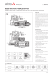
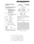
www.atos.com
Table FS230-1/E
Digital servoproportionals with integral axis controller
direct and pilot operated directional valves with position transducer - zero overlap spool
Fieldbus
connectors
�
Force
connector
Main connector
�
Position
connector
DLHZO-TEZ-D-SF-EH-040
�
�
1
Digital servoproportionals direct or pilot
operated include valve’s driver + axis
controller to perform the position closed loop of any linear or rotative hydraulic
actuator.
The controlled actuator has to be equipped with integral or external transducer (analog, potentiometer, SSI or Encoder) to
feedback the axis position.
Directional servoproportionals are operated by an external or internally generated
reference position signal (see 2 ).
S option adds alternated pressure/force
control to the basic position one (see 3 );
1 or 2 pressure/force transducers and
a second pressure/force reference signal
are required.
Atos PC software allows to customize the
controller configuration to the specific
application requirements.
Atos also supplies complete servoactuators integrating servocylinder, digital servoproportional valve and axis controller,
fully assembled and tested.
MODEL CODE
DLHZO
- T
EZ - D - SF - EH - 0
4
Direct operated
servoproportional
sleeve execution:
DLHZO = size 06
DLKZOR = size 10
0 - L5
1 /
*
Hydraulic options see tech table FS180
Electronic options, see section 7
Fail safe type, only for configuration 4:
1 = A, B, P, T with positive overlapping (20% of spool stroke)
3 = P positive (20% of spool stroke); A, B, T negative overlapping
Spool type:
L0, L1, L3, L5, L7 = linear (L0, L1, L5, only for valve size 06)
D7 = differential-linear (as L, but with P-A = Q, P-B = Q/2)
DT7 = as D, but with non linear regulation
T5, T7 = not linear regulation (T5 only for valve size 10)
T = closed loop
1 LVDT transducer
Spool overlapping in central position: 0 = zero
EZ = integral digital driver +
axis controller
Configuration: 4 = with fail safe
Valve size, ISO 4401: 0 = 06
DHZO
- T
EZ - D - SF - EH - 0
7
Direct operated
servoproportional:
DHZO = size 06
DKZOR = size 10
/
1 = 10
*
Hydraulic options see tech table FS168
Electronic options, see section 7
Spool type:
L3, L5 = linear
D5 = differential-linear (as L, but with P-A = Q, P-B = Q/2)
Spool overlapping in central position: 0 = zero
T = closed loop
1 LVDT transducer
Configuration: 7 = 3 position, spring centered
EZ = integral digital driver +
axis controller
DPZO
0 - L5
6 = without fail safe
- L
Valve size, ISO 4401: 0 = 06
EZ - D - SF - EH - 1
Pilot operated
servoproportional:
DPZO
L = closed loop
2 LVDT transducers
EZ = integral digital driver +
axis controller
Position transducer type:
A = Analog (standard, potentiometer)
D = Digital (SSI, Encoder)
Alternated P/Q control, see section 3 :
SN = none
SP = pressure control (1 pressure transducer)
SF = force control (2 pressure transducers)
SL = force control (load cell)
6
0 - L5
/
1 = 10
*
Hydraulic options see tech table FS178
Electronic options, see section 7
Spool type:
L5 = linear
DL5 = differential-linear (as L, but with P-A = Q, P-B = Q/2)
T5 = not linear regulation (only for valve size 16)
Spool overlapping in central position: 0 = zero
Configuration: 6 = spring offset (only for spool L)
Valve size, ISO 4401: 1 = 10
2 = 16
4 = 25
7 = 3 position, spring centered
4M = 27
6 = 32
8 = 35
Fieldbus interface, USB port always present:
NP = Not Present
BP = PROFIBUS DP
BC = CANopen
EH = EtherCAT
FS230
POSITION REFERENCE MODE
2
2.1 External reference generation
Axis controller regulates in closed loop the actuator position according to an external reference position signal and to the position feedback from the actuator transducer.
External reference generation
Machine
central unit
Fieldbus network
The external reference signal can be software selected among:
Fieldbus
reference (b)
Analog reference (a) - the controller receives in real time the reference signal from the
machine electronic central unit by means analog input on the main connector.
Fieldbus reference (b) - the controller receives in real time the reference signal from the
machine electronic central unit by means digital fieldbus communication.
position
Analog
reference (a)
For BC, BP or EH fieldbus communication details, please refer to the controller user manual.
2.2 Internal reference generation
t
Axis controller regulates in closed loop the actuator position according to an internally generated reference position signal and to the position feedback from the actuator transducer.
M
Internal reference generation
The internal reference signal is generated by a pre-programmed cycle; only start, stop and
switch-over commands are required from the machine electronic central unit by means :
Machine
central unit
Fieldbus network
Fieldbus
commands (d)
- on-off commands (c)
speed profile generated
- fieldbus commands (d)
Atos PC software allows to design a customized sequence of motion phases adapted to
the specific application requirements: a range of predefined standard sequences are
available in the Z-SW software.
Start/stop/switch-over commands and reference generation type can be set for each
phase in order to realize an automatic cycle according to the application requests. Refer to
the controller user manual for further details on commands and reference generation type.
On-off
commands (c)
pos
switch-over points
M
Start / stop / switch-over commands examples
External digital input
on-off commands, on main connector, are used to start/stop the cycle generation or to change the motion phase
External fieldbus input on-off commands, by fieldbus communication, are used to start/stop the cycle generation or to change the motion phase
Switch by position
switch-over from actual to following motion phase occurs when the actual position reaches a programmed value
Switch by time
switch-over from actual to following motion phase occurs after a fixed time, starting from the actual phase activation
Reference generation types examples
Absolute
a target position reference signal is internally generated for each motion phase; maximum speed and acceleration can be set to
obtain a smooth and precise position control
Relative
as ‘Absolute’ but the target position corresponds to the actuator position plus a fixed quote internally set by software
Time
as ‘Absolute’ type but the controller automatically determines the speed and acceleration in order to reach the target absolute
position in the fixed time internally set by software
3
ALTERNATED POSITION / FORCE CONTROL
S option allows to add the alternated force closed loop control to the actuator’s standard
position control, requiring one or two remote transducers (pressure or force) that have to
be installed on the actuator, see below functional schemes.
The position/force controls are operated according to two separate reference signals and
a dedicated algorithm automatically selects which control is active time by time.
forward
force
movement
control
backward force
movement
control
speed profile generated
The dynamics of the switching between the two controls can be regulated thanks to specific software setting, in order to avoid instability and vibrations.
Position control is active (see phase and at side) when the actuator force is lower
than the relevant reference signal - the valve controls the actuator position by closed-loop
regulation.
t
force
reference value
actual value
Force control is active (see phase and at side) when the actuator actual force, measured by remote transducers, grows up to the relevant reference signal - the controller
reduces the valve’s regulation in order to limit the actuator force; if the force tends to
decrease under its reference signal, the position control returns active.
t
Alternated control configurations
SP
SF
CONTROLLER
CONTROLLER
CONTROLLER
DRIVER
P
L
M
M
M
DRIVER
SL
P
DRIVER
P
A
A
B
T
B
P
P
T
one remote pressure transducer has to be
installed on the actuator’s port to be controlled
T valve’s spool transducer
A
B
P
T
T
T
T
two remote pressure transducers have to be one load cell transducer has to be installed
installed on the actuator’s ports; the actuator force between the actuator and the controlled load
is calculated by the pressure feedbacks (Pa - Pb)
M actuator’s position transducer
P
pressure transducer
L
load cell
SP – position/pressure control
Adds pressure control to standard position control and permits to limit the max force in one direction controlling in closed loop the pressure acting on one
side of the hydraulic actuator. A single pressure transducer has to be installed on hydraulic line to be controlled.
SF – position/force control
Adds force control to standard position control and permits to limit the max force in two directions controlling in closed loop the delta pressure acting on
both sides of the hydraulic actuator. Two pressure transducers have to be installed on both hydraulic line.
SL – position/force control
Adds force control to standard position control and permits to limit the max force in one or two directions controlling in closed loop the force performed by
the hydraulic actuator. A load cell has to be installed on hydraulic actuator.
General Notes:
- servoproportional type DLHZO, DLKZOR and DPZO-L are strongly recommended for high accuracy applications - see tech tables FS180, FS178
- auxiliary check valves are recommended in case of specific hydraulic configuration requirements in absence of power supply or fault - see tech table E115
- for additional information about alternated P/Q controls configuration please refer to tech table GS212
- Atos technical service is available for additional evaluations related to specific applications usage
4
APPLICATION EXAMPLES
Multiaxis simulators
To obtain the desired simulation effects, the machine central electronic unit
of multiaxis simulators generates the time-dependent motion profiles and
synchronizes all the controlled axis.
position
DLHZO-T high performance servoproportional valve in steel sleeve execution allows to obtain fast, accurate and reliable movements of the system.
M
CONTROLLER
Axis controller allows high performance position control and easy optimization of the system architecture thanks to:
t
- analog position reference mode for real time motion profile synchronization
- analog position transducer for reliable and compact solution
- complete diagnostic functionalities for advanced system monitoring
DRIVER
A
B
P
T
T
Process valves
position
Process valves motion regulation requires smooth and remote controls due
to wide distributed applications.
M
t
CONTROLLER
Axis controller allows remote control thanks to:
speed profile generated
0
1
1
DRIVER
A
B
P
T
t
T
DHZO-T proportional valve with spool position transducer allows smooth
regulations and accurate movements.
- internal reference generation with maximum speed and acceleration settings for standing alone axis control
- potentiometer position transducer for compact and cost effective solution
- fieldbus connection for easy parameterization and remote commands
Hydraulic presses
speed profile generated
Hydraulic presses perform shaft assembly with and accurate force and position control. Several set of motion parameters can be internally stored and
selected by machine electronic control unit to adapt the presses performances to the specific production.
L
DLHZO-T high performance servoproportional valve in steel sleeve execution allows to obtain accurate position and force controls in a single device.
force
CONTROLLER
0
1
1
Axis controller with force control (SL control) performs position/force control
thanks to:
DRIVER
A
B
P
T
- fieldbus reference mode for remote control
- encoder position transducer for accurate position control loop
- one load cell for alternated force control
- complete diagnostic functionalities for advanced system monitoring
T
Clamp control on plastic machines
speed profile generated
DKZOR-T proportional valve allows to obtain quick and accurate regulations
in the different working/control phases of the machine.
M
t
force
CONTROLLER
0
1
1
DRIVER
Clamp movements involve fast/slow motion with accurate alternated position/force controls for the mould safety functions.
P
P
A
B
P
T
T
t
Axis controller with force control (SF control) simplifies the hydraulic + electronic system architecture and combines position/force regulation in a single
device thanks to:
- internal reference generation for standing alone axis control
- SSI digital position transducer for high performance solution
- two pressure transducers for alternated force control
- fieldbus connection for machine remote control and advanced diagnostics
FS230
5
MAIN CHARACTERISTICS
Power supplies
(see 7.1, 7.6)
Nominal
Rectified and filtered
: +24 VDC
: VRMS = 20 ÷ 32 VMAX (ripple max 10 % VPP)
Max power consumption
50 W
Reference input signals
(see 7.2, 7.3)
Voltage: range ±10 VDC (24 VMAX tollerant) Input impedance:
Current: range ±20 mA
Input impedance:
Monitor outputs
(see 7.4, 7.5)
Output range:
Enable input (see 7.8)
Range: 0 ÷ 5 VDC (OFF state), 9 ÷ 24 VDC (ON state), 5 ÷ 9 VDC (not accepted); Input impedance: Ri > 10 kW
Fault output
Output range: 0 ÷ 24 VDC (ON state > [power supply - 2 V] ; OFF state < 1 V ) @ max 50 mA;
external negative voltage not allowed (e.g. due to inductive loads)
(see 7.7)
voltage
current
Ri > 50 kW
Ri = 500 W
±10 VDC @ max 5 mA
±20 mA @ max 500 W load resistance
Alarms
Solenoid not connected/short circuit, cable break with current reference signal, over/under temperature,
valve spool transducer malfunctions
Position transducers power supply
+24 VDC @ max 100 mA and +5 VDC@ max 100 mA are software selectable;
±10 VDC @ max 14 mA minimum load resistance 700 W
Pressure/Force transducers power supply +24 VDC @ max 100 mA
Format
Sealed box on the valve; IP66 / IP67 protection degree
Tropicalization
Tropical coating on electronic PCB
Operating temperature
-40 ÷ +60 °C (storage -40 ÷ +70 °C)
Mass
Approx. 510 g
Additional characteristics
Short circuit protection of solenoid’s current supply; 3 leds for diagnostic; spool position control by P.I.D. with
rapid solenoid switching; protection against reverse polarity of power supply
Electromagnetic compatibility (EMC)
According to Directive 2004/108/CE (Immunity: EN 61000-2; Emission: EN 61000-3)
Communication interface
USB
Atos ASCII coding
CANopen
EN50325-4 + DS408
PROFIBUS DP
EN50170-2/IEC61158
EtherCAT
IEC 61158
Communication physical layer
not insulated
USB 2.0 + USB OTG
optical insulated
CAN ISO11898
optical insulated
RS485
Fast Ethernet, insulated
100 Base TX
Recommended wiring cable (see 13 )
LiYCY shielded cables
Note: a minimum time of 300 to 500 ms have be considered between the controller energizing with the 24 VDC power supply and when the valve is
ready to operate. During this time the current to the valve coils is switched to zero
6
CONNECTIONS AND LEDS
D1
D1
D2
L
D2
CANopen
(male)
E1
CANopen
(female)
USB
(female)
PRESSURE/FORCE
TRANSDUCERS
(female)
E2
E1
SPOOL POSITION
MAIN STAGE
(only for piloted valve)
PROFIBUS DP
(male)
PROFIBUS DP
(female)
COIL CONNECTION
(only for 05H version)
SINGLE
D1 PRESSURE/FORCE
TRANSDUCERS
L
DIGITAL POSITION
TRANSDUCER
(female)
E2
DOUBLE
D2 PRESSURE
TRANSDUCERS
EtherCAT
(female)
EtherCAT
(female)
INPUT FIELDBUS
CONNECTOR
USB CONNECTOR
(always present)
OUTPUT FIELDBUS
CONNECTOR
E1 DIGITAL POSITION
TRANSDUCER
MAIN
CONNECTOR
ANALOG POSITION
TRANSDUCER
(female)
L
L1 L2 L3
ANALOG POSITION
E2 TRANSDUCER
PE
MAIN CONNECTOR
(male)
DIAGNOSTIC LEDS
(see 6.1)
Note: connectors front view
6.1
Diagnostic LEDs
L
Three leds show controller operative conditions for immediate basic diagnostics. Please refer to the controller user manual for detailed information.
FIELDBUS
LEDS
NP
Not Present
BC
CANopen
BP
PROFIBUS DP
EH
EtherCAT
L1
VALVE STATUS
LINK/ACT
L2
NETWORK STATUS
NETWORK STATUS
L3
SOLENOID STATUS
LINK/ACT
L1 L2 L3
6.2
PIN SIGNAL
1
2
3
- see 13.1
Main connector - 12 pin
TECHNICAL SPECIFICATIONS
NOTES
V+
V0
ENABLE
Power supply 24 VDC (see 71)
Power supply 0 VDC (see 7.1)
Enable (24 VDC) or disable (0 VDC) the controller, referred to V0 (see 7.8)
Position reference input signal:
4 P_INPUT+
±10 VDC / ±20 mA maximum range (see 7.2)
5 INPUTNegative reference input signal for P_INPUT+ and F_INPUT+
Position monitor output signal:
6 P_MONITOR
±10 VDC / ±20 mA maximum range, referred to VL0 (see 7.4)
Pressure/Force reference input signal (SP, SF, SL controls):
7 F_INPUT+
±10 VDC / ±20 mA maximum range (see 7.3)
Pressure/Force (SP, SF, SL controls) or valve spool position (SN control) monitor output signal:
8 F_MONITOR
±10 VDC / ±20mA maximum range, referred to VL0 (see 7.5)
9 VL+
Power supply 24 VDC for controller’s logic and communication (see 7.6)
10 VL0 (1)
Power supply 0 VDC for controller’s logic and communication (see 7.6)
11 FAULT
Fault (0 VDC) or normal working (24 VDC), referred to V0 (see 7.7)
PE EARTH
Internally connected to controller housing
Input - power supply
Gnd - power supply
Input - on/off signal
Input - analog signal
Software selectable
Gnd - analog signal
Output - analog signal
Software selectable
Input - analog signal
Software selectable
Output - analog signal
Software selectable
Input - power supply
Gnd - power supply
Output - on/off signal
Note: (1) do not disconnect VL0 before VL+ when the controller is connected to PC USB port
6.3
Communication connectors
-
- see 13.2
USB connector - M12 - 5 pin always present
PIN SIGNAL
1
2
3
4
5
+5V_USB
ID
GND_USB
DD+
BC fieldbus execution, connector - M12 - 5 pin
TECHNICAL SPECIFICATION (1)
PIN
1
2
3
4
5
Power supply
Identification
Signal zero data line
Data line Data line +
SIGNAL
TECHNICAL SPECIFICATION (1)
CAN_SHLD
not used
CAN_GND
CAN_H
CAN_L
Shield
pass-through connection (2)
Signal zero data line
Bus line (high)
Bus line (low)
BP fieldbus execution, connector - M12 - 5 pin
PIN SIGNAL
1
2
3
4
5
+5V
LINE-A
DGND
LINE-B
SHIELD
EH fieldbus execution, connector - M12 - 5 pin
TECHNICAL SPECIFICATION (1)
TX+
RX+
TXRXHousing SHIELD
Termination supply signal
Bus line (high)
Data line and termination signal zero
Bus line (low)
1
2
3
4
Notes: (1) shield connection on connector’s housing is recommended
6.4
Remote pressure/force transducer connector - M12 - 5 pin
TECHNICAL SPECIFICATION
1
VF +24V
2
TR1
Power supply +24VDC
1st signal transducer: ±10 VDC / ±20 mA maximum range,
software selectable
Common GND for transducer power and signals
2nd signal transducer: ±10 VDC / ±20 mA maximum range,
software selectable
Not connect
AGND
TR2
5
NC
Transmitter
Receiver
Transmitter
Receiver
- see 13.3
SIGNAL
3
TECHNICAL SPECIFICATION (1)
(2): pin 2 can be fed with external +5V supply of CAN interface
PIN
4
SIGNAL
PIN
SP, SL - Single transducer (1)
Voltage
Current
Connect
Connect
SF - Double transducers (1)
Voltage
Current
Connect
Connect
Connect
Connect
Connect
Connect
/
Connect
/
/
/
Connect
Connect
/
/
/
/
Connect
Note: (1) single/double transducer configuration is software selectable - see 7.10
6.5
D execution - Digital position transducers connector - M12 - 8 pin
E1
- see 13.4
SSI - default transducer (1)
PIN SIGNAL
1
2
3
4
5
6
CLOCK+
CLOCKDATA+
DATANC
NC
7
VP
8
0V
Encoder (1)
TECHNICAL SPECIFICATION
SIGNAL
TECHNICAL SPECIFICATION
Serial syncronous clock (+)
Serial syncronous clock (-)
Serial position data (+)
Serial position data (-)
Do not connect
Do not connect
Power supply, software selectable between:
+24VDC , +5VDC or OFF (default OFF)
Common GND for transducer power and signals
/R
/R
/A
/A
/B
/B
Input channel /R
Input channel /R
Input channel /A
Input channel /A
Input channel /B
Input channel /B
Power supply, software selectable between:
+24VDC , +5VDC or OFF (default OFF)
Common GND for transducer power and signals
VP
0V
Note: (1) digital position transducer type is software selectable: Encoder or SSI - see 7.9
6.6
A execution - Analog position transducers connector - M12 - 5 pin
PIN SIGNAL
1
VP +24V
2
3
4
5
VP +10V
AGND
TR
VP -10V
TECHNICAL SPECIFICATION
Power supply, software selectable between:
+24VDC or OFF (default OFF)
Power supply reference +10VDC (always present)
Common GND for transducer power and signals
Signal transducer
Power supply reference -10VDC (always present)
E2
- see 13.4
Potentiometer
Analog
/
Connect
Connect
Connect
Connect
Connect
/
Connect
Connect
/
Note: analog input range is software selectable - see 7.9
FS230
7
SIGNAL SPECIFICATIONS
Atos digital controllers are CE marked according to the applicable directives (e.g. Immunity/Emission EMC Directive).
Installation, wirings and start-up procedures must be performed according to the prescriptions shown in tech table F003 and in the user manuals included in the Z-SW programming software.
The electrical signals of the controller (e.g. monitor signals) must not be directly used to activate safety functions, like to switch-ON/OFF the machine’s
safety components, as prescribed by the European standards.
7.1
Power supply (V+ and V0)
The power supply to the solenoids must be appropriately stabilized or rectified and filtered: apply at least a 10000 mF/40 V capacitance to single
phase rectifiers or a 4700 mF/40 V capacitance to three phase rectifiers.
A safety fuse is required in series to each controller power supply: 2,5 A fuse.
7.2
Position reference input signal (P_INPUT+)
Functionality of P_INPUT+ signal (pin 4), depends on controllers’ reference mode (see section 2 ):
external analog reference generation (see 2.1): input is used as reference for the controller axis position closed loop.
Reference input signal is factory preset according to selected valve code, defaults are ±10 VDC for standard and 4 ÷ 20 mA for /I option.
Input signal can be reconfigured via software selecting between voltage and current, within a maximum range of ±10 VDC or ± 20 mA.
fieldbus/internal reference generation (see 2.2): analog reference input signal can be used as on-off commands with input range 0 ÷ 24VDC.
7.3
Pressure or force reference input signal (F_INPUT+)
Functionality of F_INPUT+ signal (pin 7), depends on selected controllers’ reference mode and alternated control options (see section 3 ):
SP, SL, SF controls and external analog reference selected : input is used as reference for the controller pressure/force closed loop.
Reference input signal is factory preset according to selected valve code, defaults are ±10 VDC for standard and 4 ÷ 20 mA for /I option.
Input signal can be reconfigured via software selecting between voltage and current, within a maximum range of ±10 VDC or ± 20 mA.
7.4
Position monitor output signal (P_MONITOR)
The controller generates an analog output signal proportional to the actual axis position; the monitor output signal can be software set to show other
signals available in the controller (e.g. analog reference, fieldbus reference, position error, valve spool position).
Monitor output signal is factory preset according to selected valve code, defaults are ±10 VDC for standard and 4 ÷ 20 mA for /I option.
Output signal can be reconfigured via software selecting between voltage and current, within a maximum range of ±10 VDC or ± 20 mA.
7.5
Pressure or force monitor output signal (F_MONITOR)
The controller generates an analog output signal according to alternated pressure/force control option:
SN control: output signal is proportional to the actual valve spool position
SP, SL, SF controls: output signal is proportional to the actual pressure/forcel applied to the cylinder’s rod end
Monitor output signals can be software set to show other signals available in the controller (e.g. analog reference, force reference).
The output range and polarity are software selectable within the maximum range ±10 VDC or ±20 mA.
Monitor output signal is factory preset according to selected valve code, defaults are ±10 VDC for standard and 4 ÷ 20 mA for /I option.
Output signal can be reconfigured via software selecting between voltage and current, within a maximum range of ±10 VDC or ± 20 mA.
7.6
Power supply for controller’s logic and communication (VL+ and VL0 )
The power supply to the solenoids must be appropriately stabilized or rectified and filtered: apply at least a 10000 mF/40 V capacitance to single
phase rectifiers or a 4700 mF/40 V capacitance to three phase rectifiers.
Separate power supply (pin 9,10) allow to cut solenoid power supply (pin 1,2) while maintaining active diagnostics, USB and fieldbus communication.
A safety fuse is required in series to each controller power supply: 500 mA fast fuse.
7.7
Fault output signal (FAULT)
Fault output signal indicates fault conditions of the controller (solenoid short circuits/not connected, reference or transducer signal cable broken,
maximum error exceeded, etc.). Fault presence corresponds to 0 VDC, normal working corresponds to 24 VDC.
Fault status is not affected by the status of the Enable input signal.
Fault output signal can be used as digital output by software selection.
7.8
Enable Input Signal (ENABLE)
To enable the controller, a 24VDC voltage has to be applied on pin 3.
When the Enable signal is set to zero the controller can be software set to perform one of the following actions:
- maintain the actuator actual position in close loop control
- move towards a predefined position in closed loop control and maintains the reached position (hold position)
- move forward or backward in open loop (only the valve’s closed loop remain active)
- disable the valve functioning (current output stage is switched off and the valve goes in fail safe/central position)
7.9
Position transducer input signal
A position transducer must be always directly connected to the controller. Select the correct controller execution depending on the desired transducer interface: digital SSI or Encoder (D execution), potentiometer or a generic transducer with analog interface (A execution).
Position digital input signal is factory preset to binary SSI, it can be reconfigured via software selecting between binary/gray SSI and Encoder.
Position analog input signal is factory preset according to selected valve code, defaults are ±10 VDC for standard and 4 ÷ 20 mA for /C option.
Input signal can be reconfigured via software selecting between voltage and current, within a maximum range of ±10 VDC or ± 20 mA.
Refer to position transducer characteristics to select the transducer type according to specific application requirements (see 9.1).
SN control or fieldbus/internal reference selected: analog reference input signal can be used as on-off commands with input range 0 ÷ 24VDC.
7.10 Remote pressure/force transducer input signals - only for SP, SF, SL
Analog remote pressure transducers or load cell can be directly connected to the controller.
Analog input signal is factory preset according to selected valve code, defaults are ±10 VDC for standard and 4 ÷ 20 mA for /C option.
Input signal can be reconfigured via software selecting between voltage and current, within a maximum range of ±10 VDC or ± 20 mA.
Refer to pressure/force transducer characteristics to select the transducer type according to specific application requirements (see 9.2).
7.11 Possible combined electronic options:
For A-SN, A-SP, A-SF, A-SL: /I, /C, /CI
For D-SN: /I
For D-SP, D-SF, D-SL: /I, /C, /CI
8
IN / OUT FIELDBUS COMMUNICATION CONNECTOR
Two fieldbus communication connectors are always available for digital drivers executions BC, BP and EH.
This features allows considerable technical advantages in terms of installation simplicity, wirings reduction
and also avoid the usage expensive T-connectors.
For BC and BP executions the fieldbus connectors have an internal pass-through connection (see 8.1) and
can be used like end point of the fieldbus network, using an external terminator (see tech table GS500).
For EH execution the external terminators are not required: each connector is internally terminated.
8.1 - BC and BP pass-through connection
fieldbus
network
fieldbus
network
fieldbus
interface
9 ACTUATOR’S TRANSDUCER CHARACTERISTICS
9.1 Position transducers
The accuracy of the position control is strongly dependent to the selected position transducer. Four different transducer interfaces are available on
the controllers, depending to the system requirements: potentiometer or analog signal (A execution), SSI or Encoder (D execution).
Transducers with digital interface allow high resolution and accurate measures, that combined with fieldbus communication grants highest performances.
Transducers with analog interface grant simple and cost effective solutions.
9.2 Pressure/force transducers
The accuracy of the pressure/force control is strongly dependent to the selected pressure/force transducer (see section 3 ). Alternated
pressure/force controls require to install pressure transducers or load cell to measure the actual pressure/force values.
Pressure transducers allow easy system integration and cost effective solution for both alternated position/pressure and position/force controls
(see tech table G465 for pressure transducers details). Load cell transducers allow the user to get high accuracy and precise regulations for alternated position/force control.
The characteristics of the remote pressure/force transducers must be always selected to match the application requirements and to obtain the
best performances: transducer nominal range should be at least 115%÷120% of the maximum regulated pressure/force.
9.3
Transducers characteristics & interfaces - following values are just for reference, for details please consult the transducer’s datasheet
Position
Input type
Power supply (1)
Controller Interface
Max speed
Max Resolution
Pressure/Force
A
Execution
D
Potentiometer
Analog
SSI
SP, SF, SL
Incremental Encoder
Analog
±10 VDC
+24 VDC
+5 VDC / +24 VDC
+5 VDC / +24 VDC
+24 VDC
±10V
0 ÷ 10V 4 ÷ 20 mA
Serial SSI binary/gray
TTL 5Vpp - 150 KHz
±10 VDC 4 ÷ 20 mA
0,5 m/s
1 m/s
2 m/s
2 m/s
-
< 0.4 % FS
< 0.2 % FS
1 mm
1 mm (@ 0.15 m/s)
< 0.4 % FS
Linearity error (2)
± 0.1% FS
< ±0.03% FS
< ± 0.01 % FS
< ± 0.001 % FS
< ±0.25% FS
Repeatability (2)
± 0.05% FS
< ± 0.005% FS
< ± 0.001 % FS
< ± 0.001 % FS
< ±0.1% FS
Notes: (1) power supply provided by digital controller - see 6.5 and 6.6
(2) percentage of total stroke
10 PROGRAMMING TOOLS - see tech table GS500
10.1 - USB connection
Valve's functional parameters and configurations, can be easily set and optimized using Atos Z-SW programming software connected via USB communication port to the digital controller (see 10.1). Z-SW software is
available in different versions according to the controllers’s fieldbus interface: NP (Not Present) Z-SW-PS,
BC (CANopen) Z-SW-BC, BP (PROFIBUS DP) Z-SW-BP and EH (EtherCAT) Z-SW-EH.
For fieldbus versions, Z-SW software permits valve's parameterization through USB communication port also if
the controller is connected to the central machine unit via fieldbus.
E-C-SB-USB/M12 cable
WARNING: controllers USB port is not isolated!
Use of E-A-SB-USB/OPT isolator adapter is highly recommended for PC protection.
E-A-SB-USB/OPT isolator
Full programming software, to be ordered separately :
Z-SW-*
DVD first supply
= software has to be activated via web registration at www.download.atos.com ; 1 year service included
Upon web registration user receive via email the Activation Code (software license) and login data to access personal Atos Download Area.
The software remains active for 10 days from the installation date and then it stops until the user inputs the Activation Code.
Z-SW-*-N DVD next supplies = only for supplies after the first; service not included, web registration not allowed
Software has to be activated with Activation Code received upon first supply web registration
Atos Download Area: direct access to latest releases of Z-SW software, manuals, USB drivers and fieldbus configuration files at www.download.atos.com
USB Adapters, Cables and Terminators, can be ordered separately
11 MAIN SOFTWARE PARAMETER SETTINGS
For a detailed descriptions of the available settings, wirings and installation procedures, please refer to the user manuals included in the Z-SW-* DVD
programming software:
Z-MAN-RI-LEZ - user manual for TEZ and LEZ with SN
Z-MAN-RI-LEZ-S - user manual for TEZ and LEZ with SP, SF, SL
11.1 External reference and transducer parameters
Allow to configure the controller reference and transducer inputs, analog or digital, to match the specific application requirements:
- Scaling parameters
define the correspondence of these signals with the specific actuator stroke or force to be controlled
- Limit parameters
define maximum/minimum stroke and force to detect possible alarm conditions
- Homing parameters
define the startup procedure to initialize incremental transducer (e.g. Encoder)
11.2 PID control dynamics parameters
Allow to optimize and adapt the controller closed loop to the wide range of hydraulic system characteristics:
- PID parameters
each part of the closed loop algorithm (proportional, integral, derivative, feed forward, fine positioning, etc) can be modified to
match the application requirements
11.3 Monitoring parameters
Allow to configure the controller monitoring function of the positioning error (difference between actual reference and feedback) and detects anomalous
conditions:
- Monitoring parameters maximum allowed errors can be set for both static and dynamic positioning phases, and dedicated waiting times can be set to
delay the activation of the alarm condition and relevant reaction (see 11.4)
11.4 Fault parameters
Allow to configure how the controller detect and react to alarm conditions:
- Diagnostics parameters define different conditions, threshold and delay time to detect alarm conditions
- Reaction parameters
define different actions to be performed in case of alarm presence (stop at actual or preprogrammed position, emergency
forward/backward, controller disabling, etc.)
11.5 Valve characteristics compensation
Allow to modify the valve regulation to match the actuator/system characteristics and to obtain the best overall performances:
- Valve parameters
modify the standard valve regulation by means of deadband compensation, curve linearization and differentiated gain for positive and negative regulation
11.6 Motion phases parameters
When the internal reference generation is active a pre-programmed cycle can be generated; start/stop/switch-over commands and reference generation
types parameters can be set to design a customized sequence of motion phases adapted to the specific application requirements (see 2.2).
FS230
12
OVERALL DIMENSIONS [mm]
ZM-5PF - Input
E-C-SB-USB/M12
USB CABLE
cable lenght 4m
CANopen
B
ZM-5PM - Output
TEZ / LEZ
ZH-5PM/1.5
SINGLE PRESSURE/FORCE
TRANSDUCER
cable lenght 1,5m
ZM-5PF/BP - Input
D1
PROFIBUS DP
ZH-5PM-2/2
DOUBLE PRESSURE
TRANSDUCERS
cable lenght 2m
ZM-5PM/BP - Output
D2
ZM-4PM/EH - Input/Output
EtherCAT
ZH-8PM/5
DIGITAL POSITION
TRANSDUCERS
cable lenght 5m
D1
ZM-12P - 12 pin (Metallic)
D2
A1
Main
connectors
A1
E1
A2
E2
B
E1
ZH-5PM/1.5
ANALOG POSITION
TRANSDUCER
cable lenght 1,5m
ZH-12P - 12 pin (Plastic)
A2
E2
Note: use of metallic connectors is strongly recommended in order to fulfill EMC requirements
13
CONNECTORS CHARACTERISTICS - to be ordered separately
13.1
Main connectors
CONNECTOR TYPE
A1
Conductor size
ZM-12P
A2
12pin female straight circular
DIN 43651
Metallic
PG13,5
Type
Standard
Material
Cable gland
Recommended cable
POWER SUPPLY
POWER SUPPLY
CODE
LiYCY 12 x 0,75 mm2 max 20 m (logic and power supply)
0,5 mm2 to 1,5 mm2 - available for 12 wires
to crimp
IP 67
Connection type
Protection (EN 60529)
13.2 Fieldbus communication connectors
CONNECTOR TYPE
BC CANopen (1)
CODE
Type
Standard
Material
Cable gland
Cable
Connection type
Protection (EN 60529)
ZM-5PF
ZM-5PM
5 pin female
5 pin male
straight circular
straight circular
M12 coding A – IEC 60947-5-2
Metallic
Pressure nut - cable diameter 6÷8 mm
CANbus Standard (DR 303-1)
screw terminal
IP 67
0,14 mm2 to 0,5 mm2 - available for 9 wires
0,5 mm2 to 1,5 mm2 - available for 3 wires
to crimp
IP 67
BP PROFIBUS DP (1)
EH EtherCAT (2)
ZM-5PF/BP
ZM-5PM/BP
5 pin female
5 pin male
straight circular
straight circular
M12 coding B – IEC 60947-5-2
Metallic
Pressure nut - cable diameter 6÷8 mm
PROFIBUS DP Standard
screw terminal
IP 67
ZM-4PM/EH
4 pin male
straight circular
M12 coding D – IEC 61076-2-101
Metallic
Pressure nut - cable diameter 4÷8 mm
Ethernet standard CAT-5
terminal block
IP 67
Notes: (1) E-TRM-** terminators can be ordered separately - see tech table GS500
13.3 Pressure/Force transducer connectors - only for SP, SF, SL
CONNECTOR TYPE
SP, SL - Single transducer
CODE
Type
Standard
Material
Cable gland
Cable
Connection type
Protection (EN 60529)
ZH-12P
12pin female straight circular
DIN 43651
Plastic reinforced with fiber glass
PG16
LiYCY 10 x 0,14mm2 max 40 m (logic)
2
LiYY 3 x 1mm max 40 m (power supply)
(2) internally terminated
SF - Double transducers
ZH-5PM/1.5
ZH-5PM-2/2
5 pin male straight circular
M12 coding A – IEC 60947-5-2
Plastic
Connector moulded on cables 1,5 m lenght
3 x 0,25 mm2
molded cable
IP 67
4 pin male straight circular
M12 coding A – IEC 60947-5-2
Plastic
Connector moulded on cables 2 m lenght
3 x 0,25 mm2 (both cables)
splitting cable
IP 67
13.4 Position transducer connectors
CONNECTOR TYPE
CODE
Type
Standard
Material
Cable gland
Cable
Connection type
Protection (EN 60529)
DIGITAL POSITION TRANSDUCER
D execution - see 6.5
E1
ZH-8PM/5
8 pin male straight circular
M12 coding A – IEC 60947-5-2
Plastic
Connector moulded on cables 5 m lenght
8 x 0,25 mm2
molded cable
IP 67
ANALOG POSITION TRANSDUCER
A execution - see 6.6
E2
ZH-5PM/1.5
5 pin male straight circular
M12 coding A – IEC 60947-5-2
Plastic
Connector moulded on cables 1,5 m lenght
4 x 0,25 mm2
molded cable
IP 67
14
INSTALLATION DIMENSIONS DLHZO and DLKZOR [mm]
DLHZO-TEZ-*
155
1
ISO 4401: 2005
Mounting surface: 4401-03-02-0-05
(see table P005)
Fastening bolts:
4 socket head screws M5x50 class 12.9
Tightening torque = 8 Nm
Seals: 4 OR 108; 1 OR 2025
Diameter of ports A, B, P, T: Ø 7,5 mm (max)
165
135
ISO 4401: 2005
Mounting surface: 4401-05-04-0-05
(see table P005)
Fastening bolts:
4 socket head screws M6x40 class 12.9
Tightening torque = 15 Nm
Seals: 5 OR 2050; 1 OR 108
Diameter of ports A, B, P, T: Ø 11,2 mm (max)
15
7
66
15
136
46
Mass: 2,3 kg
DLKZOR-TEZ-*
135
15 1
138
13
100
46
Mass: 4,3 kg
1
15
= Space to remove main connector. For main and communication connectors see section
12 , 13
INSTALLATION DIMENSIONS DHZO and DKZOR [mm]
DHZO-TEZ-*
15
155
1
135
90.5
66
136
46
ISO 4401: 2005
Mounting surface: 4401-03-02-0-05
(see table P005)
Fastening bolts:
4 socket head screws M5x50 class 12.9
Tightening torque = 8 Nm
Seals: 4 OR 108; 1 OR 2025
Diameter of ports A, B, P, T: Ø 7,5 mm (max)
Mass: 3,1 kg
DKZOR-TEZ-*
135
1
165
15
138
1
16
92.5
100
ISO 4401: 2005
Mounting surface: 4401-05-04-0-05
(see table P005)
Fastening bolts:
4 socket head screws M6x40 class 12.9
Tightening torque = 15 Nm
Seals: 5 OR 2050; 1 OR 108
Diameter of ports A, B, P, T: Ø 11,2 mm (max)
46
Mass: 5 kg
= Space to remove main connector. For main and communication connectors see section
12 , 13
INSTALLATION DIMENSIONS DPZO [mm]
DPZO-LEZ-1*
15
271
1
184,5
100
ISO 4401: 2005
Mounting surface: 4401-05-05-0-05
(see table P005)
Fastening bolts:
4 socket head screws M6x40 class 12.9
Tightening torque = 15 Nm
Seals: 5 OR 2050, 2 OR 108
Diameter of ports A,B, P, T: Ø = 11 mm
Diameter of ports X, Y: Ø = 5 mm
70
Mass: kg 9,5
1
= Space to remove main connector. For main and communication connectors see section
12 , 13
FS230
DPZO-LEZ-2*
252
15 1
100
230
ISO 4401: 2005
Mounting surface: 4401-07-07-0-05
(see table P005)
Fastening bolts:
4 socket head screws M10x50 class 12.9
Tightening torque = 70 Nm
2 socket head screws M6x45 class 12.9
Tightening torque = 15 Nm
Seals: 4 OR 130, 2 OR 2043
Diameter of ports A, B, P, T: Ø = 20 mm
Diameter of ports X, Y: Ø = 7 mm
92
Mass: kg 14
DPZO-LEZ-4*
1
281
15
100
285
ISO 4401: 2005
Mounting surface: 4401-08-08-0-05
(see table P005)
Fastening bolts:
6 socket head screws M12x60 class 12.9
Tightening torque = 125 Nm
Seals: 4 OR 4112; 2 OR 3056
Diameter of ports A, B, P, T: Ø = 24 mm
Diameter of ports X, Y, L: Ø = 7 mm
DPZO-4M
Seals: 4 OR 4131; 2 OR 3056
Diameter of ports A, B, P, T: Ø = 32 mm
Diameter of ports X, Y: Ø = 7 mm
Detail of A, B, P, T ports
118
Mass: kg 19
DPZO-LEZ-6*
1
323
15
100
395
ISO 4401: 2005
Mounting surface: 4401-10-09-0-05
(see table P005)
Fastening bolts:
6 socket head screws M20x90 class 12.9
Tightening torque = 600 Nm
Diameter of ports A, B, P, T: Ø = 34 mm
Diameter of ports X, Y: Ø = 7 mm
Seals: 4 OR 144, 2 OR 3056
203
Mass: kg 43
DPZO-LEZ-8*
417
15 1
100
450
199
Mass: kg 80
1
04/15
= Space to remove main connector. For main and communication connectors see section
12 , 13
ISO 4401: 2005
Mounting surface: 4401-10-09-0-05
(see table P005)
Fastening bolts:
6 socket head screws M20x100 class 12.9
Tightening torque = 600 Nm
Diameter of ports A, B, P, T: Ø = 50 mm
Diameter of ports X, Y: Ø = 9 mm
Seals: 4 OR 156, 2 OR 3056