1
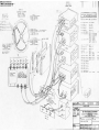
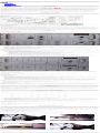
The 2.1-m Chopping Secondary User's Manual
●
●
●
●
●
●
●
1. Introduction
2. Secondary Mirror
3. Installation & Setup
4. Operation
5. Troubleshooting
6. Appendix
7. Removing the Central Cone
1. Introduction
The f/15 chopping secondary for the 2.1-m telescope was the first servo-controlled secondary to be driven in both orthogonal axes by independent drivers under computer control.
At the time of its construction in 1985, two-position chopping with single-element infrared detectors was still in use, and the two-axis capability permitted the continuous selection
of both position angle and amplitude, up to 90 arcsec. At the relatively short infrared wavelengths ( < 5 m) now supported at Kitt Peak, chopping is not required, and the
secondary is used in fixed mode, with the dc offsets providing collimation adjustment.
2. Secondary Mirror
The secondary was designed at a focal ratio of f/15 to be compatible with the infrared instrumentation at that time. This focal ratio is still used with SQIID, IRMOS, and some
visitor instruments. Because of the size (375 mm diameter) and weight of the mirror, great care was taken to design resonance frequencies above the servo response and to isolate
the system from coupling to the telescope structure. The primary step in this effort was the inclusion of a "counterforce mirror" having the same moment of inertia, driven out of
phase with respect to the secondary by drivers mounted on a common surface. The net force of the secondary and counterforce mirrors on the rest of the support structure is thus
nearly zero.
To minimize the thermal background seen by the detector, the entire secondary top ring was designed to minimize the ambient temperature structures in the optical path. The
support and focus mechanism is smaller in diameter than the secondary and is thus shielded from the detector. The spider supports were made as thin as possible. Finally, a
reflective cone corresponding to the area shadowed by the central hole in the primary was mounted in the center of the secondary; this is designed to reflect skylight into this
region of the secondary, as seen from the detector. This cone can be removed (section 7) for use with optical instrumentation, where the sky is brighter than the telescope
environment.
3. Installation & Setup
The f/15 secondary requires setup in two locations, the telescope itself and in the control room where the driver electronics are located. Figure 1 is a (rather complex) guide to the
wiring connections. A full scale version is available for those requiring additional scrutiny.
Figure 1: Schematic of Chopping Secondary Electronics
Secondary Installation
The physical installation of the secondary is a significant effort involving the day crew. The entire f/8 secondary ring must be removed and lowered to the ground floor with the
crane, and the f/15 secondary ring must be brought up and installed on the top of the telescope. This procedure takes at least a couple of hours.
Driver Electronics
The control rack resides permanantly in the control room just inside the door to the dome. Unless it has been removed for any reason, the AC power and cables W15 and W16
should be plugged into their appropriate connectors on the secondary control rack. (Note: The cables W13 and W14 shown in Fig. 1 are no longer used, since the CAMAC-driven
options, to say nothing of the control room CAMAC rack itself, are no longer used).
Out in the telescope dome, W15 and W16 plug into a connector box on the NW side of the telescope, near the level of the declination axis. The cables are strung on a springloaded cable which must be connected to an eye bolt near the declination axis drive, to keep them from fouling as the telescope is moved about. Ensure that the cables are plugged
in securely, as the screw-type connector provides the only security against their falling out. The continuation of these cables must be removed from a dummy connector box at the
top of the telescope and installed on the connectors on the outer secondary ring junction box.
The flatfield lights on the top of the secondary ring must be plugged in, using the cable also to power the flatfield lights on the f/8 secondary. Carefully remove the protective
clamshell cover from the secondary itself. If the "Christmas" alignment lights are required for SQIID, install them at this time when the secondary is easily accessible. The band
containing the four lights should be secured just behind the mirror, not on the mirror itself.
4. Operation
Description of Control Rack
The control rack contains five modules for drive and control of the f/15 secondary. There is, in addition, a PAR lock-in amplifier used in the past for single-channel IR photometry,
which should be powered off and ignored. The five f/15 modules are shown schematically in Fig. 1, although they are arranged differently in the control rack. Although the f/15 is
no longer used for chopping, the control electronics provide the collimation tilts and hold the secondary mirror in position, so proper operation of these electronics is required. A
description of the modules and their front panel controls follows, from top to bottom of the rack:
Figure 2: The Focus Control and Chopper Control Modules
Focus Control Module (Fig. 2)
This module controls the focus of the secondary mirror. Only manual control from the front panel or a hand paddle is possible, and the focus servo is not implemented. The f/15
secondary focus is self-contained, and the mirror position is not displayed on the VDU or read into image headers.
●
●
●
●
●
●
●
●
POWER -- Power switch for the focus module
MOTOR POWER -- Indicator should light if power is on and the secondary is connected
JOG IN/OUT -- Manual toggle switch to adjust focus
SPEED -- Potentiometer to control speed of focus motion using the JOG switch. The focus handpaddle, if selected, has its own speed potentiometer
CONTROL MODE -- Three-position switch to select focus control input from a) front panel (JOG IN/OUT) switch; hand paddle (which must be plugged into the connector
below this switch); c) auto position (servo control not implemented).
SERVO ON/OFF -- Autofocus servo indicator (not implemented)
MOTOR OVERCURRENT -- Reset circuit breaker
FOCUS READOUT -- LED readout of focus position. One unit = 28.6 microns of secondary motion. Typical settings are 3.2 for CRSP/IRIM and 5.2 for SQIID.
Chopper Control Module (Fig. 2)
This module selects the operating mode and reference input. Front panel potentiometers control the signal/reference attenuation and offset in each axis in the ANALOG mode. For
the sake of completeness, all of the functions are described below, although only one configuration is presently used.
●
●
●
●
POWER -- Power switch for the control module
EXT. INPUT -- BNC input for reference signal. In ANALOG mode, the input provides the driving signal for the mirror motion, which may be of any amplitude, waveform,
or frequency, subject to the mechanical limitations of the mirror motion. The CHOP RATE mode utilized the input as a frequency reference for a programmed square wave
chop controlled by CAMAC (no longer implemented).
X, Y AXIS CONTROLS -- These operate only in ANALOG mode.
❍ SIGNAL -- Enables the signal input (from the EXT. INPUT) to that axis
❍ SIGNAL ATTEN -- inputs 0 - 100% of the signal input to the drivers for that axis.
❍ OFFSET -- Enables a DC offset to the position in each axis, independent of any external signal input
❍ OFFSET LEVEL -- Controls the DC offset in each axis. Full range (0-100) is approximately 300 arcsec, with null input at the potentiometer setting of 50. 10 units
on dial are approximately 30 arcsec. This is presently the only active control on the f/15 secondary, used for collimation.
❍ OUTPUT -- Provides full range of position angle by permitting inversion of one or both of the axis signals.
SOURCE SELECT -- Selects the reference input
❍ LOGIC/CHOP -- Full computer control from CAMAC (not implemented)
❍ COLLIMATE -- Ground all input to mirror control, independent of SIGNAL or OFFSET settings.
❍ EXT CHOP RATE -- Square wave chopping of secondary at frequency of EXT INPUT reference signal (no longer implemented).
❍ EXT ANALOG -- Analog control of secondary by EXT INPUT reference signal and/or OFFSET control.
NOTE: The only configuration used with the IR imager/spectrometers is a static mode in which the OFFSET is employed as a collimation control. For this application, the
SOURCE SELECT must be in the EXT ANALOG position, the OFFSET switches must be on, and the OFFSET LEVEL is used to adjust the tilt of the secondary in each axis.
Figure 3: The Chopper and Counterforce Servo Modules
Chopper Servo Module (Fig. 3)
This module contains the servo and drive amplifiers for the chopping secondary mirror. To protect the mirror and drive electronics, the SERVO button will activate the servo
feedback only when the POWER is on. The RESET button will reset the servo in the event of an overcurrent condition in the motor driver amplifier. The LED panel meter may be
used to display the X and Y motor power, and the X and Y POSITION MONITOR BNC jacks may be output to an oscilloscope or digital voltmeter for diagnostic purposes.
Counterforce Servo Module (Fig. 3)
This is identical to the Chopper Servo Module, driving the counterforce mirror out of phase with the secondary to minimize the net inertia.
Power Supply
This contains power supplies for the focus motor and transducers and has a single power switch.
Operation Checklists
Startup & Operation
●
●
●
●
●
●
●
●
In initial setup, verify connection of driver cables W15 and W16 to the control rack, telescope, and secondary assembly. Make sure all module power switches are OFF
when connecting or disconnecting these cables.
Make sure that control rack AC power cable is installed and power switch on back of rack is ON.
Turn on power switches on all five modules (focus power supply, chopper servo, counterforce servo, chopper control, focus control). Check for a reasonable number (e.g.,
3.20) on the focus readout. A blank or zero reading may indicate that the cables are not properly connected to the secondary.
Turn MOTOR POWER switches on both chopper servo and counterforce servo ON.
Press SERVO ON buttons on both chopper and counterforce servo modules. The green LEDs should light up.
Ensure that the SOURCE SELECT on the chopper control module is set to EXT ANALOG. Do not adjust the OFFSET potentiometers unless you are sure what you are
doing! In any case, record the settings prior to any adjustment
Make sure the plastic shield is installed over the control modules. This prevents inadvertant deactivation of the servos should one brush up against the control rack.
Once a star is acquired, one may focus using either the front panel JOG IN/OUT switch with the CONTROL MODE set to FRONT PANEL or the handpaddle with the
CONTROL MODE set to HANDPADDLE. The handpaddle is usually situated near the observer's console. The SPEED potentiometer may be used to adjust the focus
motion speed.
Shutdown
There is no need to shut down the secondary at the end of the night, although it is a good idea to check that the SERVO ON lights are illuminated at the beginning of a night's
observing. If powering down is necessary (at the end of an observing run), the following sequence is recommended to avoid overdriving the motors:
●
●
●
Press SERVO OFF buttons on both chopper and counterforce modules. The red LED should light.
Turn MOTOR POWER switches on both chopper and counterforce modules OFF.
Power down the five modules in the control rack.
Collimation Adjustment
As noted above, the OFFSET LEVEL potentiometers are used to tilt the secondary for collimation purposes. In the event of suspected decollimation, we strongly suggest
consulting with cognizant personnel before adjusting these levels. In any case, record the settings before making any adjustment, so that the initial conditions can be recovered. If
adjustment yields improved collimation, record the information on the white board in the control room and through a note in SERVICE so that the information can be recorded in
the log.
5. Troubleshooting
As long as all the connections are secure and the electronics are operating properly, not much can go wrong. The most likely failure is a motor overcurrent condition, which results
in tripping one or both of the servo circuit breakers. In such an event, the green SERVO LED will go out and the red LED will light. If this occurs in the mirror servo unit, the
mirror will "relax" and the object will most likely move out of the field. Servo failure in the counterforce only will have no visible effect and will not affect the operation if one is
not chopping.
If an overcurrent occurs as a result of attempting to overdrive the secondary, the SERVO RESET button should restore proper operation. If the servo continues to trip, monitor the
X and Y motor currents with the panel meter on the appropriate servo module. Persistent ramping up to an overcurrent condition suggests a problem with either hardware (such as
physical binding of the mirror motion) or electronics.
If the image appears comatic and/or the pointing is very bad, check that the motor servos are enabled (green LED is lit). Also check that the SOURCE SELECT is on EXT
ANALOG and that the OFFSET switches are on.
6. Appendix -- Panel Settings
The following table gives measurements of the voltage outputs at the monitor, servo, and counterforce test points for X and Y as a function of the OFFSET LEVEL potentiometer
settings. These measurements were made with the SIGNAL ATTEN potentiometers set to 0.0, the SIGNAL switch OFF, and the OFFSET switch ON.
Position
Offset
Collimate
Monitor
Servo
Counterforce
X
Y
X
Y
X
Y
X
Y
----
----
.000
.000
.020
-.093
.029
.019
Ext Analog Non
0.0
0.0
-8.53
-8.93
4.14
4.22
4.15
4.32
Non
2.5
2.5
-4.26
-4.43
2.08
2.06
2.10
2.15
Non
5.0
5.0
-0.068
-0.063
0.057
-0.051
0.071
0.048
Non
7.5
7.5
4.12
4.28
-1.96
-2.14
-1.95
-2.05
Non
10.0
10.0
8.38
8.78
-4.02
-4.36
-4.02
-4.21
Inv
10.0
10.0
-8.47
-8.81
4.11
4.14
4.12
4.26
Inv
5.0
5.0
0.058
0.061
-0.002
-0.135
-0.014
-0.009
Inv
5.02
5.17
0.087
-0.207
-0.007
0.001
-0.012
0.098
Several important results from this table:
●
●
●
●
●
There is an offset between the input voltage to the servo (as measured from the MONITOR output on the Chopper Control panel) and the actual servo X and Y outputs. In
particular, the COLLIMATE switch sets the input values to 0.0, but the servo outputs are nonzero.
When the SOURCE SELECT switch is in the COLLIMATE position, the voltages are independent of the position of the SIGNAL and OFFSET switches or potentiometers.
The MONITOR outputs are always 0.0.
The INVERT/NONINVERT switch simply flips the input about the midpoint. Thus, a setting of 10.0 in the INVERT mode is the same as 0.0 in the NONINVERT mode.
Near a potentiometer setting of 5.0, the INVERT/NONINVERT switch has little effect.
The full scale deflection of 150 arcsec corresponds to about 4.2 volts at the servo monitor. Thus 1 arcsec is approximately 28 mv.
After a motion from a zenith distance of 75 degrees to the zenith, the Servo X and Y voltages shifted by about 30 mv. This should have no consequences for observing.
As of October 2000, the telescope collimation for f/15 is optimized by setting the primary support readouts to the values determined by C. Claver and the secondary so that the
Servo X and Y outputs are 0.0. This requires the following procedure:
SIGNAL switches OFF
SIGNAL ATTEN potentiometers set to 0.0
OFFSET switches ON
INVERT/NONINVERT switches to INVERT (not necessary, but suggested for consistency)
SOURCE SELECT switch to EXT ANALOG
OFFSET LEVEL potentiometers adjusted to give 0.0 v output on X and Y
Servo Position Monitor.
7. Removing the Central Cone
Occasionally, the f/15 secondary is used with visitor instruments at optical wavelengths, where the sky is brighter than the telescope baffles. In such cases, the reflective central
cone would increase, rather than decrease the background level, so it is removed for use with such instruments. Since the cone itself is slightly oversized to give a 3 arcmin field of
view, removal actually decreases the central obscuration and increases the effective telescope collecting area from 2.83 to 3.11 m2.
Removal of the cone is relatively straightforward, as it is mounted on a shaft which extends into the center of the secondary (through a hole in the secondary mirror itself), held in
place by a single set screw. The telescope must be moved through the slew limit to an extremly south declination ~ − 45 to access the secondary mirror. Although this task can be
carried out by a single person, it is easier and safer to have a second person standing by to help with tools and the cone itself after removal. In addition, because the cone has a
delicate evaporated gold coating and one must work in close proximity to the reflective surface of the secondary mirror, it is imperative that a protective glove be worn on the
hand used to handle the cone!
1. Begin by gathering the necessary materials.
●
●
●
●
Custom cardboard box for the secondary cone (usually kept in the locker in the CCD fill room).
Clean room glove (to be worn on the hand extracting the cone).
1/16 allen wrench
1/8 ball driver with extension and snap-on handle
2. Move the telescope to declination − 45. It will be necessary to use the SEARCH button once one hits the slew limit at ~ − 40.
3. Carry all of the tools up to the access level. You will probably also need the short steps. The secondary with the cone will appear as in Fig. 4a.
4. Remove the access panel on the W side on the top of the secondary, which is held in place by at least two 4-40 button head screws, using the 1/16 allen wrench (Fig. 4b).
Figure 4: (left) View of the 2.1-m f/15 secondary with the central cone, taken with the telescope in the far south. (right) View of the top of the secondary, illustrating the access
panel which must be removed.
5. Snap together the 1/8 ball driver, extender, and handle and carefully insert the driver into the access hole (Fig. 5a). Unscrew the set screw at least 5 or 6 revolutions. The
secondary cone shaft is a fairly snug fit, so it will not fall out on its own.
6. With the gloved hand, grab the edge of the cone and pull it out carefully. If it will not come out all the way, unscrew the set screw a few more turns. Put the cone into the custom
box and tape the box cover shut to keep the cone protected.
Figure 5: (left) After the access panel is removed, the long 1/8 allen ball driver is inserted into the set screw access hole. (right) View of the secondary with the central cone
removed.
7. Screw the locking set screw in a couple of turns so it does not fall out and replace the access cover.
8. Store the box containing the cone in a safe place, such as the locker in the CCD fill room.
9. Reverse the above steps to reinstall the cone, ensuring that the set screw is initially removed so that the shaft is completely inserted and that the notch is aligned with the set
screw.
[email protected]