1
1101_mcc_gui_and_to_panel.doc
Version: 2014-03-18
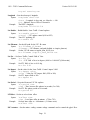
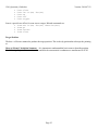
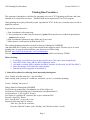
TO Panel
MCC Graphic User Interface
TO Hand Paddle
A Reference for the Telescope Operators.
Page 1
1101_mcc_gui_and_to_panel.doc
Version: 2014-03-18
1. Introduction ......................................................................................................................................................... 3
2. The TO (Telescope Operator’s) Panel ................................................................................................................ 4
3. MCC GUI............................................................................................................................................................ 6
3.1 General Layout.............................................................................................................................................. 6
3.2 Main Buttons ................................................................................................................................................. 6
3.3 MCC main tabs ............................................................................................................................................. 6
3.4 GUI CLI interface ......................................................................................................................................... 7
3.5 Notices dialog window ................................................................................................................................. 7
3.6. MCC1 TAB.................................................................................................................................................. 8
3.7. MCC2 Tab ................................................................................................................................................. 16
3.8. MCC3 Tab ................................................................................................................................................. 19
3.9. Balance Tab ............................................................................................................................................... 21
3.10. Pointing Tab ............................................................................................................................................. 25
3.11. Details Tabs ............................................................................................................................................. 27
4. The TO (Telescope Operator’s) Hand Panel .................................................................................................... 28
Page 2
1101_mcc_gui_and_to_panel.doc
Version: 2014-03-18
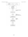
1. Introduction
The TO Panel is a hardware panel located in the operator area. This panel is use by the operator and provide
hardware based input to the TCS3.
The MCC GUI (Master Control Console) is an X11 Windows-based application running on the TCS3
computer (hostname t1). This provide the Graphic User Interface for the Operator. Normally two copies are
running on the TCS3 duel monitors located at the TO area. Up to five copies can be running at once. Normally,
only the two TO copies of the GUI should be running.
The TO Hand Paddle is a hardware panel located in the operator’s area. This hand paddle provide some offset
and pointing map buttons.
Page 3
1101_mcc_gui_and_to_panel.doc
Version: 2014-03-18
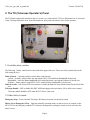
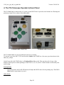
2. The TO (Telescope Operator’s) Panel
The TO Panel is physically attached to the tcs3 system via a cable into the T3 Servo Electronic box. It is located
in the Telescope Operators Area. It provide numerous safety and convenience items for the operator.
2.1 Lockable safety switches
The following 3 safety controls are located with in the upper-left cover. These are safety controls that can be
lock (using the key).
Dome Control – 3 position switch to select dome control mode:
Locked – Software will not allow any movement (MCC GUI and Dome Handpaddle locked out).
Handpaddle – Only the Dome handpaddle will control the dome’s movement (software is locked out).
Software – Dome control via the MCC GUI is enabled (Dome Handpaddle is locked out).
Limit Override – ON (Green LED is on) mean to override the hardware stop & brake limits for the HA & Dec
axis.
Telescope Enable – OFF to disable HA,DEC AMP and engage telescope brakes. ON to allow servo control.
Telescope enable should be OFF when the TCS Servo is not used.
2.2 Other Safety Controls
Emergency Stop – Press to disable Telescope & Dome movements via the safety board.
Mirror Cover Emergency Close – Open the normally operation mode, as mirror covers are control via the
MCC GUI. In an Emergency (and the TCS software in inoperable), setting the switch to close will close the
mirror covers.
Page 4
1101_mcc_gui_and_to_panel.doc
Version: 2014-03-18
There are 3 switch to control the max velocity of the telescope. There are 2 velocity limits in the tcs: 400 as/s,
and 1600 as/s.
Automatic/Unsafe – When in Automatic , velocity of 1600 as/s is allow. When in unsafe, 400 as/s is the
velocity limit, unless overridden by the One Shot or Supervised switch.
Supervised – During some moves (ie: slewing), the velocity limit can be raised to 1600 as/s by depressing this
momentary switch. The ideal is the TO are to visually ‘supervised’ the telescope when pressing this switch.
One Shot Supervised and Supervised can be pressed together to allow the 1600 as/s limit for the duration of
the move.
The Automatic & One Shot can be secured using the eyelet, allowing only the Supervised high speed moves.
Safety Board OK LED will be on when there are no latched errors on the safety board.
System Power LED is on when the system power is ON.
Brake ON LED is on when the HA & Dec brake are ON.
2.3 Remaining Controls
The TO Joystick is a self-centering 2 axis joystick. It is used for error adjustment during tracking, and velocity
adjustment during MV moves. Review track and MV servo modes for MCC1.
During tracking the TO Joystick’s can be used to adjust the pointing map in NSEW or Spiral mode. The toggle
switch to the right of the joystick enables you to control this mode.
The Floor light control the dimmer for the Dome floor light. This hardware contol is independent of the
computers.
The Dome Light (Off/On) control the dome florescence light via the tcs3 software.
The Humidity LED display the relative humidity (0 to 100%).
Page 5
1101_mcc_gui_and_to_panel.doc
Version: 2014-03-18
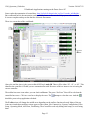
3. MCC GUI
The MCC GUI (Master Control Console) is an X11 Windows-based application running on the TCS3 computer
(the computer t1). It provides the Graphic User Interface for the Operator. Normally two copies are running on
the TCS3 duel monitors located at the TO area. Up to five copies can be running at once (for example, another
computer displayed via Max). Normally, only the two copies of the GUI should be running.
3.1 General Layout
The GUI application has 3 main sections:
Main Buttons
MCC main tabs
MCC CLI (command line interface)
3.2 Main Buttons
At the top of the MCC GUI, the following Main Buttons appear:
About – brings up an ‘about’ dialog box.
FB0 to FB6 – the GUI provides six Function Buttons. Function buttons can execute tcs commands stored in a
text file. To associate a text file with a function button, you would enter the command: m.SetButton #
$PATH $FILENAME. For example:
m.SetButton 0 /home/tcs3/data/mcc_macros zenith
would set FB0 to run the file “zenith” from path “/home/tcs3/data/mcc_macros”. The FB0 button
would then execute it.
Hints: To make a macro file assignment permenant, place it in the ~/current/to/main/mcc/.mcc-init file.
Stop – cancel the currently executing macro file.
Notices – Brings up the ‘Notices’ popup dialog window for controlling sounds related to warning
notices (see 2.1.4).
Quit – exits the GUI
3.3 MCC main tabs
The GUI is organized as a set of tabs on the main window. Each tab will be covered in a separate section in this
document.
Mcc1
Mcc2
– Mostly concerned with the HA, Dec, Dome and shutter control.
– General facility IO and show next object buffers.
Page 6
1101_mcc_gui_and_to_panel.doc
Version: 2014-03-18
Mcc3 – Less frequently used MCC widgets.
Balance – Counter weight control
Pointing – Pointing Map related widgets.
Details – Provides access to engineering screens which display many internal TCS3 variables.
3.4 GUI CLI interface
This is the GUI Command Line Interface (CLI). Here you can manually enter tcs commands. First put your
mouse cursor in the CLI area, then type in commands. Some status data also appears in the output window.
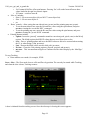
3.5 Notices dialog window
When the ‘Notices’ button on the main window is pressed, a dialog popup appears which allows control of
sounds associated with the warning notices which are displayed in the mcc1 Warnings window. The dialog
looks like:
The entries in the dialog box correspond to the list of possible error and warning notices that can be displayed in
the ‘Warnings’ display area on the mcc1 window (see 2.2.4). If the check box to the left of an entry has a check
in it, then if that message is activated in the ‘Warnings’ display an associated sound will be played about every
15 seconds. Uncheck the box to deactivate the sound associated with that notice message. Once the dialog box
is visible, it can be dragged to any location on the desktop. To hide the dialog box, click the ‘Hide’ button at
the bottom of the box.
Page 7
1101_mcc_gui_and_to_panel.doc
Version: 2014-03-18
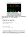
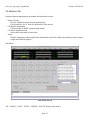
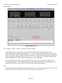
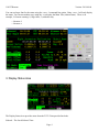
3.6. MCC1 TAB
The MCC1 tab primarily contains widget that are concerned with the telescope, dome, and shutter positioning.
Also some safety and warning indicators are located here.
Time & Position display
On the top, the sky RA, HA, Dec, and their non-sidereal rates are display in yellow text.
The the right, the time is display in HST, UTC, and the Sidereal Time.
There are 2 diagram to represent the HA and Dec axis. Note the HA diagram is using East-to-the-left display
convension.
• The larger yellow arrow is the current desired telescope position.
• The larger gray arrow should the actual position of the servo (often covered by the yellow arrow).
• The mangenta line indicated where the software limit are.
• The inner dial show the speed of the axis using an arrow and text in arcsec/sec.
Page 8
1101_mcc_gui_and_to_panel.doc
•
•
Version: 2014-03-18
The yellow bars below the diagram indicate the AMP command voltage to each of the 2 motor for each
axis.
The APE position is display in cyan, along with the difference of the APE and IE (incremental encoder).
The ‘Misc’ box in this display contains other positional and environmental information.
Dome/Shutter display & control
This window contains 3 sections:
Dome Feedback
• The blue circle/dome show the azimuth of the slit. The Dm AZ: is the Dome’s slit azimuth. North is on
top and East (90 deg Az) is on the left.
• The yellow arrow show the azimuth of the telescope. Err: shows (obs_az – dome_az).
• The Operator Inputs list some IO setting important to dome control: state of the Brakes; DAC output to
the dome amps (volts), and the velocity of the dome (deg/sec).
• The IO Output show state of brakes, DAC (Amplifier input voltage), and dome velocity (in deg/sec).
Shutter Feedback
• The yellow arrow show the telescope’s elevation, on the blue side view of the dome/slit.
• The blue shows a side view of the dome and illustrates the shutter’s open position. The shutter opening
is divided in to 3 segments. The meaning of the the top and bottom segments are:
o Zenith to 1.125 Air mass (ZD 90 to 27.3 degrees) would be the area covered by the lower shutter
when it is in its highest position (ULimit + Touch).
o 1.5 Air mass to bottom (ZD 48 to 70 degrees) show the position of the lower shutter when it is
down (DLimit)
• The magenta line illustrate is where the Horizontal hardware limits is (approx ZD of 70 degrees).
• The bottom has indicator for Upper Shutter UP (ULimit), Shutters Touching (Touch) , and Lower
Shutter Down (DLimit) shutter switches.
Dome/Shutter control widgets.
• For software dome control to work, you much select Software on the Dome_Cnlt=Software on the TO
Panel.
• The Dome Software Modes are : Lock, Manual, Auto, Goto.
o Lock – Software will not attempt to move the dome.
o Manual – using the widget provided, the operator has full manual control of the dome.
The slider allows you to control the range to apply of the dome amps, ie: 0.5 is half range
(5V), 1.0 is full range (10V).
The buttons will command the dome to move left, right, or stop.
o Auto – Auto mode will attempt to position the dome at the current telescope’s Azimuth.
o Goto – Allows the operation to enter the destination azimuth for a dome move.
• Shutter control – 2 sets of button are used to control the upper & lower shutter. Select Open or Close to
move the appropriate shutter cart. You must click and continue holding the mouse during the move.
Releasing the mouse button will stop the operation.
Limits display
This display shows the status of various limit switches, the system brakes, and system power.
Page 9
1101_mcc_gui_and_to_panel.doc
Version: 2014-03-18
A grid showing the state of the Slew, Software, Stop, and Brake limits for each axis (N, S, E, W), and the state
of the Horizon Slew and Stop. These GUI’s LED will blink with the limits are ON.
Override Software limits = Override toggle on MCC2 GUI is checked.
Override Hardware limits = Override limit switch on TOP is ON.
Telescope at Zenith = Both the HA and DEC hardware ‘Zenith’ indicator is ON.
Platform not stowed = platform under the telescope warning.
Closed-cycle cooler off = Cooler is off warning.
Primary mirror color on = Air blowing across the primary mirror warning.
Brake Off/On – indicates the state of the servo (HA/Dec) brakes.
Sys Pwr On – indicates the state of switch line power.
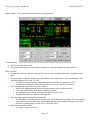
Servo
This window show the current servo mode. Steps for operation each servo mode is provide.
Servo - Stop – When the servo mode is STOP, the pmac PID loop is disabled (open Loop mode), and the
brakes are ON. To exit stop mode, select another mode.
Stop mode means the servo is OFF. Brakes are On.
The label “TOP Telescope Enable is OFF/ON” indicates the state of the telescope enable switch on the TO
Panel. When operator is not present in the TO area, this should be OFF to prevent remote uses from running the
TCS.
Function you can perform in Stop mode:
• APE.Set.PMAC – The command initializes the position in the PMAC motor controller using the current
APE position, or “Apes set the PMAC”. This should be done at zenith at the start of the observing night.
Page 10
1101_mcc_gui_and_to_panel.doc
•
•
Version: 2014-03-18
SafetyBrd.Reset – Sents a reset to the TCS3 safety board. When the safety board has errors, they are
latched until the errors are cleared. Once cleared, you can resume servo operation. This button issues the
safety board reset command.
Hello TCS3 – A button that plays a sound file.
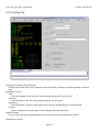
Servo - MP – MP is Move Position. This mode allows the operator to move to a HA Dec absolute position.
To perform an MP move:
• Click on the MP radio button to enter MP mode.
• Enter your HA, Dec destination position, and velocity, OR
• Press the buttons on the right (Top Ring Down, Stow, Zenith) to auto fill the HA, Dec destination
positions with a pre determined position.
• Click on Execute MP Move to begin.
While in MP:
• The Servo window displays the status of the current move.
• The velocity is limited to 400 as/s unless the OneShow, Safe or Supervised buttons are used to allow
high speed moves.
• You can enter new HA, Dec, Vel values and press Execute MP Move while a move is in progress.
To stop an MP move:
• Press the Stop MP Move button
Servo - MV – MV is Move Velocity. This mode allows the operator to move the telescope by specifying a
velocity for each axis.
Page 11
1101_mcc_gui_and_to_panel.doc
Version: 2014-03-18
Enter the MV mode by clicking on the Servo Mode’s MV radio button. You can now control the velocity using
3 methods: Joystick, DomeHP, or GUI. All inputs are used simultaneously.
Joystick:
• Enable the TO Joystick. (and Disable DomeHP).
• Enter your desired rate.
• Use the TO Panel’s Joystick to change the velocity.
Dome HP
• Enable the DomeHP (and disable Joystick).
• Enter your desired rate.
• Use the dome hand paddle N,S,E,W buttons to move the telescope.
GUI
•
•
•
•
Disable both the Joystick and DomeHP.
Enter a HA and Dev velocity.
Press ‘Execute MV’ to set telescope velocity.
Press ‘Stop’ to set velocity to 0.
In the status area, the following information is displayed.
• The requested velocity is the sum of the Software + Joystick + domeHP inputs. The PMAC velocity is
the commanded velocity to the motor controller. The bar graph displays to actual motor’s velocity.
• The OneShot, Safe, and Supervised labels are colored GREEN or Gray to reflect the state of these
TOPanel switches.
• Software label will be green if the rates are enter via the GUI, below show the requested rates in “/s.
Enabling the Joystick or Dome Handpaddle will set the Joystick ON or DomeHP On labels green. If
any buttons are pressed to command a velocity the ‘N S E W’ char will turn green.
Page 12
1101_mcc_gui_and_to_panel.doc
Version: 2014-03-18
Servo - Track – Track mode tracks the RA and Dec target position.
To start tracking:
• Click on the track radio button.
• The position table (display in the feedback window) is used to determined the target position.
While Tracking:
• Position and offsets are display on the top left. Various rates (and other information ) is display on the
right.
• The performance of the RTCS and servo system (Motors) are summaries in “Servo Performance”. The
status should always be “Good” or “OK”.
o Good RTCS status means the commanded position to the PMAC matches the VTCS.
o Good PMAC performance means the motor servo error is less that 0.1 arcseconds.
• The “Pointing Map” status shows key map variables.
o MAdj is the MapAdjustment register (Map adjustments preserved during slews)
o Corr is the total from the Peak, Spiral, and Rates registers.
o The pointing rates are shown, but group with other telescope rates.
o The Spiral Position (in rotation) is also displayed.
• The lower-right status area has miscellaneous data
o The ‘MeaWgt=’ label identifies the current value for the measurement widget. The measurement
widget allow you to measure offset and Pointing map movement without needing to clear either
the offset or pointing map. Use the ‘mw.z’ tozero the values.
• Beam Switch controls include:
o ‘A’ button – switch to beam A.
Page 13
1101_mcc_gui_and_to_panel.doc
•
•
•
Version: 2014-03-18
o ‘Set’ button & RA/Dec offset spin buttons– Pressing ‘Set’ will set the beam offsets to these
values loaded in the spin box numeric inputs.
o ‘B’ button – switch to beam B.
‘Slew to’ includes:
o Slew 0 – Slews to next object #0 (see MCC2’s next object list).
o Slew 1 – Slew to next object #1.
o etc
‘Rates’ controls – allow setting the non-sidereal rate (ns.rate) and the pointing map rate (pt.rate).
o To set the non-sidereal rate, enter the RA and Dec values using the spin buttons, and press
ns.rate to issuing the ‘ns.rate RA DEC’ command.
o To set the pointing map rate, enter the RA and Dec values using the spin buttons, and press
pt.rate to issuing the ‘ps.rate IH ID’ command.
Pointing buttons include:
o Update– Issues the ‘pt.madj’ command to transfers correction (peak, spiral, rates) to the MAdj
register. The MAdj registers hold IH, ID values that are saved from slew to slew.
o Save – Does a ‘pointing update and saves the IH/ID values to disk to be restored when starting
the IC, or when doing a Last( pt.restore).
o Last – Restore the MAdj values saved to disk with ‘pt.restore.
o Pt.clear – Clears the Corr pointing registers (Pt.peak, pt.spiral, and pt.rates).
o mw.zero - This ‘measurement widget zero’ button zeros the values display by the ‘MeaWgt=’
label.
To stop Tracking:
• Enter another servo mode, for example, STOP.
Servo - Slew – The Slew mode slews to a RA and Dec sky position. The can only be started while Tracking,
and when the slew is done, Tracking resumes.
A slew is initiated from the tracking screen. Once the telescope is slewing this screen appears.
Page 14
1101_mcc_gui_and_to_panel.doc
Version: 2014-03-18
The status area display the estimated time to completion. The setting of the OneShot, Safe, and Supervised
buttons are display. The HA/DEC velocity and Distance Left are display using a bar graph and text.
•
•
Slew.Abort – Aborts the current slew. The current position is loaded into the tracking table’s base, and
tracking resumes.
ReSlew – Re commands the PMAC to slew. Due to a bug, some times the slew doesn’t move the
telescope (sits there with 0 velocity). Press this button to re-command the slew.
Once the slew is done, the TCS will automatic start tracking.
Warning display
This window is used to display error and warning notices. A sound is associated with each notice, and the
sounds may be controlled by the ‘Notices’ dialog (see 2.1.4). If the error or warning condition no longer exists,
the message(s) will be cleared from the screen. Notices are displayed in order of importance.
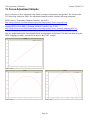
In this sample display, warning notices are shown that indicate a
counterweight stuck during a balance operation and that the current
humidity level matches or exceeds the humidity warning threshold as
currently set. Both of these conditions will cause a warning sound to be
played every 15 seconds.
In this sample display, the same warnings are active as in the previous
example, but the ‘Notices’ dialog has been used to deactivate the sounds
associated with the humidity warning. This is indicated by the red symbol
to the left of the warning text (an ‘S’ with a line through it).
Page 15
1101_mcc_gui_and_to_panel.doc
Version: 2014-03-18
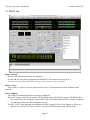
3.7. MCC2 Tab
Motor Currents:
Ha, Dec, and Dome motor currents are displayed.
For HA and Dec, the yellow graphs show the differences of the motors (scaled up by 2 x)
Operators need to monitor this while tracking to insure the telescope is in balance.
Mirror covers:
Select ‘Shut’ or ‘Open’ to close or open the mirror covers. The bottom label provide feedback on the
position.
Mirror Support:
The voltage for monitoring the mirror pressure is displayed.
Below the voltage, use the mirror.support OFF/On button to turn off/on the air support. The label to show
the current state of the air support control (Off or ON). This button issues the mirror.support command.
You muse be at Zenith for this command to execute.
The OK / FAULT label indicates the condition of the Kill_Support IO line. If Air Support is off due to a
hardware error, the FAULT label is shown. You must clear the hardware fault, then press the
Page 16
1101_mcc_gui_and_to_panel.doc
Version: 2014-03-18
‘Fault.Ack’ button to return on an OK status. Then you may turn on Mirror Support (using the OFF/On
button)
Collimate:
To change collimation, you must have the collimation enabled by checking the enable checkbox.
Use the slider to set the desired increment value for the + and – buttons.
Click on the ‘E’, ‘W’, ‘N’, or ‘S’ button to change the desired collimation position
The Goto or desired position is shown in the Text Entry widget. You can also enter the desired postion in
the text widget ( remember to hit return) to specify the desired dpos.
The actual position, or apos, is shown next to the label ‘Actual’. Green text indicated the actual position in
within range of the desired position, otherwise the value is displayed in red.
On the bottom, a label show with secondary (chopper or hexapod) is currently in use.
Collimate/Focus Table:
The collimate table provides up to 10 preset collimation and focus positions for various instruments. To set the
collimation using the table:
1. Enable Collimation and Focus
2. Click a button in collimation table. This will set the collimation and Focus Dpos to values stored in the
table, and the collimation should move to this new position.
The button’s Text colors provide the following information:
Green = Collimation Desired Position match this entry in the collimation table.
Black = This entry’s position doesn’t match the current collimation’s dpos.
Gray = This is a unused table entry (text should say ‘unused’).
The data in the collimation table is read from /home/to/data/collimation.txt. Using a text editor you can update
the entries in this file, or add new items. More detailed instruction on how to edit the collimation table is located
the in 1201_Operators_Guide. This file is read when the IC is started. To re-read the file, type
‘collimate.table.read’ in the CLI interface. The FIOC Details display should the collimation table data for tcs3.
Mirror Cooling
There are 2 widget for Mirror Cooling:
1) A radio button to set the mirror cooling mode to off, manual, or auto. Selecting the radio button will issue the
mc.mode command to the TCS.
2) A label to show a status string. This is a short description on the mirror cooling status, some example are:
“MC is OFF” – summary of mc.mode off (Fan OFF, Heater OFF, Actuator at 0 volts)
“Manual Mode. Fan=On Heat=Off Act=10.0v” – summary of manual mode. The default setting for
manual mode is for the cooling to be ON.
“AUTO and cooling ON.” – Mc.mode is Auto, and cooling is ON ( Fan ON, Heater OFF, Actuator at 5
volts).
“AUTO. Defrost 99%” – Mc.mode is Auto, but in Defrost mode (Fan OFF, heater ON, Actuator 0
volts), the percent indicate how long you are in the defrost cycle (about 30 minutes long).
“AUTO but cooling OFF” – mirror is below set point.
For detail status on the mirror cooling, see the Detail Tab, and view FIO_MC on the MCC GUI.
For addition documentation on mirror cooling see the TCS3 Design Documents T3-315x in
http://irtfweb.ifa.hawaii.edu/~tcs3/tcs3/Design/document_index.html.
Laser Traffic:
These widget provide frequently used Laser Traffic options. When Lct.Enable is ON, the system should write
the telescope position to the web site. The Ltc.impact checkbox when check will set IMPACT=YES.
Page 17
1101_mcc_gui_and_to_panel.doc
Version: 2014-03-18
Focus:
This is the chopping secondary focus control , disable the focus when not using the chopper.
You can set the desire focus position by editing the “Goto” value. Either enter the value in the text entry
area, or use the -/+ button to increment the desired position. The slider at the bottom controls the
increment amount. This Goto value will update if the desired position is changed.
The Actual label show the actual position of the focus mechanism in volts as sampled by the TCS A/D. The
text will be RED until the focus moved to the desired position.
The Focus.Enable check button, until Enable or Disables the software control loop to move the focus
mechanism.
The Focus.Adj.Enable determine if the focus adjustment value is added to the user_dos to determine the
desired postion.
If the tcs see the apos is not changing when commanded to move, a Focus_Stuck warning is display on
MCC1.
Misc:
Hum.wn – This slider widget sets the Humidity Warning level. The page values is set to 5.
Wind.wm – This slider sets the High Wind Warning value in MPH. The page value is set to 5.
Software Limit Override – Toggles the Sw.limits.override Off or On. When checked, software limits are
ignored. See MCC GUI’s Details -> Position table for value of various limits.
Hor Slew Limit Override – Toggles the HSlew.Limit.Override Off or On. When checked, the horizon slew
hardware limit which limits velocity to 400 as/s is ignored.
Next Object List:
Display the next object list. The tcs3 ‘Next’ command allow users to send slew request positions to the
tcs. This request are display here. To slew to one of the item on the list use the ‘Slew N’ command,
where N is a value from 0 to 5.
If a proper motion is in excess of 10 arcseconds per year, the PM values are colored red. Bad proper
motion value had been sent to the TCS, this warning will help flag potential bad slew destinations.
System Power – Turns off or On the system power.
Macro Dialog Box:
To the right the macro dialog box is available. Text files of TCS3 commands can be execute by
selecting, the pressing the Exec button. The directory contains the macro files is print at the top of the
macro box. You can use a text editor / file manager to inspect/maintain these files.
Page 18
1101_mcc_gui_and_to_panel.doc
Version: 2014-03-18
3.8. MCC3 Tab
Motor Currents:
Ha, Dec, and Dome motor currents are displayed.
For HA and Dec, the yellow graph shows the differences of the motors (scaled up by 2 x)
Hand Paddles: Options for each physical TCS3 hand paddles. Each hand paddle that has a N,S,E,W button has
a set of widget to control the following properties:
Enable – Off/On to disable or enable hand paddle inputs.
Swap E/W – swap the E/W directions on the hand paddle.
Swap N/S – swap the N/S directions on the hand paddle.
Rate (as/s) – enter the velocity applied with the hand paddle’s NSEW buttons.
‘E W N S ‘ – these label indicate the status of the handpaddle button: Black=off; Green=ON or pressed.
The TOHP, also has the following labels to indicate the status of the following inputs (Black=off; Green=on):
X5 = 5x rate switch.
BS = beamswitch request button
Offset = pointing (off) or offset (On) adjustment mode.
Gotobase = goto base request button
Engineering Options and PID
Page 19
1101_mcc_gui_and_to_panel.doc
Version: 2014-03-18
Item in these window are engineering option. Daycrew/TOs should not change them unless directed by
the TCS3 technical support staff.
Vtcs.offset.opt – controls how the offset are added to the base, resulting in the target destination for
tracking.
Hist_ON –Use this check box to enable/display the recording of the tcs History Data, 10 sec buffer of
various TCS3 servo information at 20Hz.. This data is display in the Details tab’s Perf-T and Perf-G
displays.
Hist.Save – This button will write the contents of the History Data Buffers to the History Directory. This
History Data Buffer hold 10 sec of various servo variables, sampled at 20Hz.
The following widget are not documented in this manual. Again see the tcs3 programmer for details. They
should not be changed by the daycrew or TO unless directed by the TCS programmer.
ServoOpt.Enable
AutoPID
Track.NoIOnOffset.HA
Track.NoIOnOffset.Dec
Hexapod.Init – This button is request the fio_hexe run the hexapod init script. This script initializes the
hexapod. However, this can also be accomplished using the hexeGUI, plus the HexeGUI provide better
feedback that the TCS.
Page 20
1101_mcc_gui_and_to_panel.doc
Version: 2014-03-18
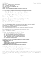
3.9. Balance Tab
Common elements appearing on the manual and auto mode screens:
Motor Currents:
Ha, Dec, and Dome motor currents are displayed.
For HA and Dec, the ‘d’ show the differences of the motors.
CW.Enable checkbutton
Click to enable or disable counterweight control.
CW Mode dropdown menu
Select either the manual or auto mode.
Status
Window displaying counterweight status information such as the enable status and any current counterweight movement in progress.
Auto Mode:
Auto Mode Screen
‘UP’, ‘DOWN’, ‘EAST’,’ WEST’, ‘NORTH’, ‘SOUTH’ buttons [auto mode]:
Page 21
1101_mcc_gui_and_to_panel.doc
Version: 2014-03-18
Clicking these button will changed the Desired Position of the counterweights. The Actual Position is
displayed on the widget. After changing the DPos, position display changes to Red and display both the
desired and actual in this format, 0.00 >> 1.00. When the DPos has been reached, the display returns to
black.
An ‘(S)’ in the position display indicates the counterweight is stuck – it has stop moving but has not reached
it desired position.
An ‘(L)’ indicates it has reached a limit set in the software and can not be moved further in auto mode.
Notes:
The numbers next to each counterweight name refers to the counterweight numeric ID.
If counterweights are not enabled, the brakes are on, or the power is off, a warning message will appear
in the status window.
Because the voltage indicating counterweight position fluctuates slightly, the test for reaching the
desired position does must allow for this. This may result in the counterweight stopping at a position
which does not exactly match the desired position voltage. .
Increment
Slider used to set the amount of voltage increment added or subtracted by each click on an ‘UP’, ‘DOWN’,
‘EAST’, ‘WEST’, ‘NORTH’, or ‘SOUTH’ button.
Balance Files
Counterweight position settings may be saved and restored as named files. The current save path is
shown above the file list window. Executing a position file will load in the saved position for each
counterweight, and the TCS will cycle through the counterweights to moving each one into positions. To
save a set of counterweight positions, enter a file name in the file entry box and click the ‘Save As’ button.
To execute a saved file, click on the file in the list and then click the ‘Exec’ button. The ‘Refresh’ button
relists the files in the balance file directory. The directory path man be changed by the “CW.Dir” command
(see the 1101_command user’s manual document).
The default CW.dir is “/home/tcs3/data/cw”.
By convention, the files are named using these rules:
1st name is capital, showing the instrument in the center of MIM.
Upto 3 names show what else is installed in the MIM.
Last part is the day the file was created in MMDDYY.
Name and date separted by “_”.
For example, this name “CSHELL_spex_hipwac_8wnm_020906” was created with CSHELL in the
middle, and spex, hipwac, 8wnm installed on the MIM. Balance was done on Feb 09, 2006.
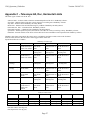
The content of the file is:
CW.Dpos 1
4.015
CW.Dpos 2
6.310
CW.Dpos 3
1.275
CW.Dpos 4
1.264
CW.Dpos 5 -4.966
CW.Dpos 6 -5.015
CW.Dpos 7 -0.819
CW.Dpos 8 -0.905
Page 22
1101_mcc_gui_and_to_panel.doc
Version: 2014-03-18
CW.Dpos 9 -2.248
CW.Dpos 10
5.158
CW.Dpos 11
5.066
The CW.Dpos is a TCS command to set the desired position of the counter weight.
The 2nd field is the counterweight numeric ID.
The 3rd field is the desired position of the counter weight in volts.
Page 23
1101_mcc_gui_and_to_panel.doc
Version: 2014-03-18
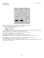
Manual Mode:
Manual Mode screen
‘UP’, ‘DOWN’, ‘EAST’, ‘WEST’, ‘NORTH’, ‘SOUTH’ buttons:
These buttons operate as in the auto mode to control the direction of movement for the selected
counterweight, however in the manual mode the + or – control voltage will be applied for as long as the
button is selected or until the counterweight hits a hard limit. In the manual mode only the actual position
voltage is displayed, without the direction arrows, ‘(S)’ or ‘(L)’ indicators. The minimum and maximum
position limits for each counterweight are displayed in [ ] in its button labels.
One other difference between the auto and manual modes is that some of the counterweights may be
operated as linked pairs. This is implemented by the wide buttons linking pairs of counterweights. For
example, The wide UP(+) under TVF(3) and TVF(4) move both counterweight up.
Note:
A warning appears in red in the status window if the mirror cover is closed, the system power is off, or the
brakes are on since these will impact dynamic balancing (see screen shot above).
Page 24
1101_mcc_gui_and_to_panel.doc
Version: 2014-03-18
3.10. Pointing Tab
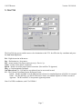
Pointing File Settings and Coefficients:
Displays the current values of the parameters associated with a pointing run and the pointing correction
map.
Pointing File Setup:
Path:
Enter the full path for the directory where pointing run data file is to be stored.
Filename:.
Enter the name for the file where pointing run data is to be stored.
Separation:
Enter the number of degrees separation between stars in the pointing array to be generated.
Caption:
Enter a caption to be stored as part of the pointing file header information.
Open File button
Press to create and open the pointing file and to write out the header information to the file.
Pointing Run Control:
Page 25
1101_mcc_gui_and_to_panel.doc
Version: 2014-03-18
Get Next Star button
Press to load the position information for the next pointing target in the array.
Slew Next button:
Press to start the telescope slewing to the loaded target star position.
Next & Slew – combines the Get Net Star and Slew Next buttons.
Add Star button:
When the telescope has completed slewing to the target, press this button to store the telescope
pointing information for the target star into the pointing file. Checking the ‘Do Map Adjust (Pt.map)’ will
also add the offset to the pointing adjustment register. Checking the ‘Do Next & Slew’ will (after saving the
data), get the Next Star and start the Slew.
The pointing run procedures are documented in document 1201_pointing_run.doc under the tcs3 user’s guide.
Follow these procedure when doing a pointing run.
Page 26
1101_mcc_gui_and_to_panel.doc
Version: 2014-03-18
3.11. Details Tabs
The details tab provide access to engineering screens where the detailed information on the TCS3 can be
viewed. To be used by the technical staff for trouble shooting. The individual items are not covered in this
document, only a summary of the available engineering displays are listed:
Pos
Time
Graph1
Graph2
PMAC
App
FIOA
FIOB
FIOC
FIOD
FIOE
FIOF
FIOMC
FIOX
Astronomy and servo motor positional data.
Time and other VTCS informaiton variables.
Performace graphs for TCS, mostly show server performance..
Performace graphs for TCS, has motor current, collimation, focus, and guider corrections..
The PMAC motor control details.
Internal TCS3 & MCC process and application data.
Facility IO device fioa details.
Facility IO device fiob details
Facility IO device fioc details
Facility IO device fiod details
Facility IO device fioe details.
Facility IO device fiof details.
Facility IO device for the Mirror Cooling IO.
Facility IO details for misc processes:
Dome Serial input process details.
Fio_ape process details.
Laser Traffic Control details.
IQUP Wind Speed details.
Queries to smokey (IRTF Guider).
Page 27
1101_mcc_gui_and_to_panel.doc
Version: 2014-03-18
4. The TO (Telescope Operator’s) Hand Panel
The TO Hand Panel is attach to the tcs3 system via the FIOCD box. It provides some buttons for offsetting and
point map control. Here a photo of the hand paddle:
TO Hand Paddle (Top View)
TO Hand Paddle (Front-side).
The TO Hand Paddle is to be used while the telescope is tracking.
To activate it, go to the MCC3 GUI and check the enable in the TOHP box. Also enter your desired rate in the
rate (“/s) prompt..
On the front side of the TOHP, there is a Pointing/Offset slider switch. This sets the mode of some of the
buttons on the top face to either pointing or offset. The N, S, E, W, and Go To Base button are affected by this
mode setting:
Pointing Mode:
In pointing mode, the N, S, E, W buttons will adjust the IH/ID values for the pointing map. The Go To
Base button is equivalent to a pt.save.
Offset Mode:
Page 28
1101_mcc_gui_and_to_panel.doc
Version: 2014-03-18
In offset mode, the N, S, E, W buttons will adjust the UserOS values. The Go To Base button will set
the UserOS to 0,0.
The Beam Sw. button will toggle the Beam Position.
The N/S Swap switch will swap the direction of the N and S buttons.
The E/W Swap switch will swap the direction of the E and W buttons.
The 5 X Rate slider will set the rate to 5 times the rate set in the mcc3 GUI’s rate value for the TOHP.
Page 29
1102 T3Remote
Version: 2011-09-06
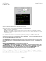
T3Remote
The Remote GUI for TCS3
Page 1
1102 T3Remote
Version: 2011-09-06
T3Remote............................................................................................................................................................... 1
1. Introduction......................................................................................................................................................... 3
2. T3Remote............................................................................................................................................................ 3
3. Display Status Area............................................................................................................................................. 4
4. Offset Tab ........................................................................................................................................................... 6
5. Next Tab.............................................................................................................................................................. 7
6. Focus Tab............................................................................................................................................................ 8
7. (User) Spiral Tab................................................................................................................................................. 9
8. PtMap Tab......................................................................................................................................................... 10
9. CMD Tab .......................................................................................................................................................... 10
Page 2
1102 T3Remote
Version: 2011-09-06
1. Introduction
T3Remote is a mini-gui for the tcs3. It is intended to be used by observers and the Telescope Operator. It is
installed and runs on the IRTF workstation. Multiple copies can be running by various number of users.
To start t3remote, type “t3remote” on you console terminal. The GUI should appear.
Usage: t3remote [–d] [–h hostname]
-d
Turn on the debug flag.
-h hostname Sets the tcs3 computer’s hostname
-m
Use Medium size font for status. Hides the Main Tabs window.
-l
Use Large size font for status. Hides the Main Tabs window.
-t
Tabs only. The status display is hidden.
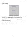
2. T3Remote
The GUI has 2 main sections:
Status Display
Main Tab provides various types of control widgets to the TCS3.
Here is a picture of the GUI:
Page 3
1102 T3Remote
Version: 2011-09-06
You can use larger font for the status using the –m or –l command line option. Using –m or –l will only display
the status. You can run another copy using the –t, to display the Main Tab (without status) . There is an
example, 2 t3remote running: 1) large fonts, 2) with tabs only.
> t3remote –l
> t3remote –t
3. Display Status Area
The Display Status Area provides status from the TCS3. Data provided includes:
Sidereal – The Local Sidereal Time.
Page 4
1102 T3Remote
Version: 2011-09-06
Hour Angle – The observed Hour Angle position.
UTC – Coordinated Universal Time
HST – The local time, Hawaii Standard Time.
Airmass – Air mass
Shutter – Time in HH:MM until the shutter will block the field of view.
CS – The Celestially Coordination frame of reference for the RA and Dec positions.
J2000 = The FK5 reference frame using the Equinox of J2000.0
B1950 = The FK4 reference frame using the Equinox of B1950.0
App = Topocentric Apparent.
Other the ‘FK4’ or ‘FK5’ is display with its Equinox values.
Right Ascension – Target Right Ascension (target is base position + offsets ).
Declination – Target Declination
Object Name – The object name field from the ptable (TCS3 position table).
Proper motion – display proper motion ra (s/yr) and dec (“/yr).
Non-Sidereal – The non-sidereal rate in “/s.
Mag. – The magnitude value from the position table.
User – User offset magnitude display; color coded yellow when applied, gray when disabled.
Beamswitch A or B – Indicates the beam position, and offset magnitude.
Scan – offset applied from the scan offset.
Total – display the total offset added to the base, resulting in the target RA Dec position.
Focus – display the actual focus position (actual is the position sensor value).
Temp. – The temperature in degree C.
TCS Mode – provide to operating mode of the TCS. They are:
Stop – telescope is parked: servo is off; brakes are on.
MP – Move Postion mode (non-observing positional moves).
MV – Move Velocity mode (non-observing velocity moves).
Track – Track the sky position specifed by the tracking table.
slew – Slewing to a tracking position.
To the right of TCS Mode, relevant status is displayed for current TCS Mode.
During tracking, you may see:
Dome is ready
Dome moving..sec (where sec is estimated seconds in current move)
Dome blocking FOV (Field of view)
During Slew, the estimated time to the end of the slew is displayed.
GuideMir: Display the location of the off/on axis guider mirror.
Out – means the mirror in out of the optical path (green text).
In – means the mirror is blocking the optical path to the instrument (Red)
Unkn – means the position is not known by the TCS.
Guiding – Indicates if guiding is active (YES) or not (NO). Guiding YES, occurs when peaking up the pointing
map using the guider or manually. YES is display when the TCS receives 5 guiding updates within the last 60
seconds.
Page 5
1102 T3Remote
Version: 2011-09-06
4. Offset Tab
The Offset Tab allows the users to increment the base coordinates and/or offsets.
First select the coordinate to change from the top radio buttons:
Base – Base RA and Dec position
UserOS – User offsets.
BeamOS – Beam offsets.
Use the spinbuttons (yellow and magenta input fields) near the bottom to set the magnitude of the offset. Units
are in arc seconds, and the color indicate the which buttons they are for.
The Rot= input specifies a rotation for the offset request. The units are in degrees.
Click on the Arrow Buttons to move or change the OS values.
The swap E/W or swap N/S allows you to change the direction of the buttons.
The kbd input, when checked, allow the keyboard arrow key to function like the Yellow buttons.
The NewBase button will make the current position the new base (zeroing any active offsets).
The Goto Base button will zero the user offset (using “user.set 0 0 “).
The Beam Switch button’s label will read Beam A or Beam B to indicated the current beam position. Press this
button to toggle the beam position.
Page 6
1102 T3Remote
Version: 2011-09-06
5. Next Tab
The Next Tab also you to send the next or slew destination to the TCS. Just fill in the sky coordinate and press
the Sent Next Obj button.
RA – Right Ascension in hh:mm:ss.
Dec – Declination in +/-deg:mm:ss.
PM – proper motion. RA proper motion in sec/yr, Dec in “/yr.
Name – a name for the object. (Optional)
Epoch – Epoch is used for proper motion correction. (Not used for CS Apparent)
Mag – a visual magnitude (optional)
Non-sidereal rate “/s – RA and Dec non-sidereal rates in arcseconds/second.
CS – The Celestial Coordinate System Reference Frame:
B1950 – The RA and DEC is in the FK4 Reference Frame. Its standard Equinox of B1950.0 is assumed.
J2000 – The RA and DEC is in the FK5 Reference Frame. Its standard Equinox of J2000 is assumed.
Apparent – The RA and DEC is in topcentric apparent position.
Note: For ICRS coordinates, used CS of J2000.0.
Page 7
1102 T3Remote
Version: 2011-09-06
6. Focus Tab
The Focus Tab allows the observer to change the telescope focus.
The top radio buttons identifies which focus hardware you wish to command:
None: disable focus communications.
Chopper: Commands the chopping secondary focus via the tcs3 (This is the default IRTF secondary).
Hexapod: Commands the hexapod secondary focus via the hexe deamon. (NOTE: this hasn’t be tested or
used for many years).
You can decrement or increment the desired focus position by pressing the “-“ and “+” buttons. The
incremented amount is control by the slider below labeled “Increment”. You can also enter the desired focus
value in the text entry widget (then hit RETURN).
The Actual Position shows the focus position sensor value. When Focus.Enable is ON, the software control
loop will drive the focus to the Desired Position. Red means the focus is out-of-position, Green mean it is inposition.
Status or feedback information is presented in the black display area.
The Desired Pos is where the focus mechanism is commanded to. The position is determined by the User
Dpos (entered by the user) plus the Adjustment value. The adjustment value is a temperature and telescope
position adjustment applied in real-time. This adjustment values is used when Adjust.Enable is ON.
Information on how temperature and position affect focus is in the TCS3 Operators Guide.
Collimation information is also displayed here. The desired position (Dpos) and Actual position (Apos) is
display. Apos is GREEN when collimation in ‘in position’, otherwise Red is used. The Collimation Enable is
shows if the collimation software loop is active (ON) or not (OFF).
Page 8
1102 T3Remote
Version: 2011-09-06
7. (User) Spiral Tab
The Spiral Tab allows the observer to spiral the telescope. The spiral RA and Dec offset are place the the User
Offset. To sprial, check the User Spiral Enable. Note that User Spiral disables user’s offset.
Press the out button to spiral outwards, use the in button to spiral inwards.
The Position tells you your location on the spiral in terms of rotations. The RA and Dec offset values can be
seen on the Users (on the status display).
The Rate and Width is display for your reference. The TO can adjust these values using the User.Spiral.Rate
and User.Spiral.Wid commands.
The Return to Center button set the rotation to 0 (center of the spiral).
Page 9
1102 T3Remote
Version: 2011-09-06
8. PtMap Tab
The PtMap Tab is the Point Map Table. These controls should be used by the Telescope Operator only (not the
Observer).
The arrow keys allow you to peak up the IH and ID corrections values. Use the yellow and magenta spin
buttons to set the displacement, units are in arcseconds. The swap N/S or E/W check buttons allow you to
reverse the HA or Dec directions.
Adjust pt map – issues pt.madj command to add corrections values to MAdj (Map Adjustment) registers.
Adjust & Save – issue pt.save: does a pt.madj AND saves MAdj values in the ic/pt.save.txt files for recall at
restart.
Center/Clear – Issues Pt.clear to zeros the MAdj, Spiral, and Rates registers.
The pointing map spiral can be controlled using the widget in the pt.spiral frame.
Spiral out – spirals outwards.
Spiral in - spirals inwards.
Spiral center – issues Sp.center sets the rotation to 0.
The spiral Rotation, IH, ID vales are displayed inside the pr.spiral frame.
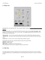
9. CMD Tab
The CMD Tab allows t3remote command to be typed in using the keyboard. These are not TCS3 command
(command defined the tcs3 command dictionary). In normal operations, neither the TO or Observer should use
this tab.
Page 10
1103 - TCS3 Command Reference
Version 2012-03-20
TCS3 Command Reference
1. Introduction
This document describes the set of commands available to the user through the TCS3 telescope control
software. These commands may be entered directly on the Command Line Interface (CLI) of the TCS3
MCC graphical user interface screens, through a telnet connection, or indirectly through the use of
widgets on the MCC screens or the t3_remote interface.
2. Summay of Commands by Catagory
2.1 Observing and Servo
Add.Offset.opt – Options when adding offset to base position.
Autopid – Enables or disable the autopid function.
Autopid.set – Specifies a set of PID coefficients.
Base - Load a new position into the position table base.
Base.inc - Increment the RA, Dec values of the base.
Beam.set - Specify the RA and Dec offsets for the beam
Beam.init – Initialize the beam offset.
Beam.inc - Apply an increment to the beam RA and Dec offsets
Beam.on or Beam.B - Enable application of the beam RA and Dec offsets
Beam.off or Beam.A - Disable application of the beam RA and Dec offsets
Beam.toggle - Toggle the beam offset enable status
Cat.search - Search catalog for the star closest to given RA/Dec within a specified radius
Cat.index - Search specified catalog by index and load results into 'next' buffer
CS - Set the default coordinate system
Epoch - Set the default epoch
Equinox - Set the default equinox
HSlew.Limit.Override – Override horizontal slew velocity limits.
Info - Return a selected subset of tcs information
Next.Clear - Clear a next star entry
Next – enter object data into the 'next' buffer (using RA, Dec coordinates).
Next.hadec – enter object data into the ‘next’ buffer using HA Dec coordindates.
NS.rate - Specifies an non-sidereal rate to be applied to the base position.
NS.rate.inc - Increments the base non-sidereal rate.
OS.2base - Transfer the enabled offsets and rates to the base and clear the offset values
MP - Execute a Motor Position move
MP.cnt - Specifiy the MP destination position in motor counts
MP.inc – Increments the MP destination position in arcseconds.
MP.Vel - Set the velocity for a motor position move
PID.Dec – Makes a requests to set the PID for the Dec axis.
PID.HA – Make a request to set the PID for the HA axis.
Polar.Motion - Specifies the earth's polar motion
Page
1
1103 - TCS3 Command Reference
Version 2012-03-20
MV - Execute a Motor Velocity move
Mw.zero – zero the measurement widget value.
Scan.Clear - Remove scan offsets to return to the original position
Scan.Go – Scans by moving to the offset ra, dec position.
Scan.Return – Scans by returning to the 0,0 offset position.
Scan.Set - Set up the parameters for scanning to an offset position
Slew - Slew to the next object in the specified buffer
Slew.Abort - Abort a slew and switch to track mode
Slew.Reslew – Re-issue a the slew command to the pmac (to fix “slew not slewing” problem).
Stop - Put the tcs system in the 'stop' mode
Sw.Limits.Override – Overrides software limt velocity controls.
Sw.Limits.Set – Set the software limits.
Track - Commands tcs to enter the 'track' servo mode
User.Inc - Apply an increment to user RA and Dec offsets
User.Init – Initialize the User Offsets.
User.Off - Disable user offsets
User.On - Enable user offsets
User.Set - Set the values for the user RA and Dec offsets
User.Toggle - Toggle the user offset enable setting
User.Spiral.Center – Move to the center of the user spiral..
User.Spiral.in – Move inwards on the user spiral trajectory.
User.Spiral.out – Move outwards on the user spiral trajectory.
User.Spiral.rate – Specify the velocity of the user spiral.
User.Spiral.stop – Stop moving on the user spiral.
User.Spiral.wid – Specify the with of 1 rotation of the user spiral
UT1Delta - Set the value of ut1 - utc.
Wavelength- Set the value of the observed wavelength
2.2. Facility Hardware Control
Ape.mode – Set the fio_ape execute mode.
Ape.Pos - Manual method for initialing the APE value.
Ape.set.pmac - Tells the tcs to initialize the position in the PMAC servo controller using the APEs..
Collimate.EW.Dpos- Set desired East/West collimation position
Collimate.EW.Dpos.Inc- Increment East/West collimation position
Collimate.NS.Dpos - Set desired North/South collimation position
Collimate.NS.Dpos.Inc – Increment North/South collimation position
Collimate.enable - Enable or disable collimation control loop
Collimate.table.read – Loads collimation table data into tcs3.
Collimation.table.set – Set the collimation desired position using the collimation table.
CW.Dir - Set the directory path for counterweight files
CW.Dpos- Set selected counterweight to position described as a voltage
CW.Enable - Enable or disable counterweight movements
CW.Manual.cntl - The CW command to set a counterweight up, down or off
CW.Mode - Select the counterweight operational mode
DHP.enable – Enables the DOME handpaddle.
Page
2
1103 - TCS3 Command Reference
Version 2012-03-20
DHP.swapEW – Swaps East and West inputs for the Dome HP.
DHP.swapNS – Swaps North and South inputs for the Dome HP.
DHP.rate – Sets the velocity for the Dome HP in as/s.
Dome.Auto.Offset – Set the an offset angle during auto (tracking) mode for dome control.
Dome.HP.Speed – Sets maximum speed for dome handpaddle mode.
Dome.Manual -Control dome motion while in manual mode
Dome.Manual.Speed – Sets the maximum speed for dome manual mode.
Dome.Mode - Set the dome movement control mode
Dome.Speed - Set the dome movement speed factor
Focus.Adj.Enable – Enables or disable the Temperatue and Position adjustment to the focus.
Focus.Enable - Enable or disable the focus control loop
Focus.Dpos - Set the desired focus position
Focus.Dpos.Inc - Increment or decrement the focus position
Hexapod.init – runs the Hexapod initialize maco file.
Humidity.Wn - Set relative humidity level to trigger warning.
Mirror.Cover - Open or close the mirror cover
MS.Support – Turn mirror support off or on.
MS.Fault.Ack - Re-enable mirror support after a fault
MC.Actuator – Mirror cooling fan control.
MC.Fan – Mirror cooling fan control.
MC.Heater – Mirror cooling Heater control.
MC.Mode – Sets the Mirror cooling mode.
MC.SetPt – Sets Mirror cooling set point temperature.
OH1.enable – Enables the OH1 handpaddle.
OH1.swapEW – Swaps East and West inputs for the OH1.
OH1.swapNS – Swaps North and South inputs for the OH1.
OH1.rate – Sets the velocity for the OH1 in as/s.
OH2.enable – Enables the OH2 handpaddle.
OH2.swapEW – Swaps East and West inputs for the OH2.
OH2.swapNS – Swaps North and South inputs for the OH2.
OH2.rate – Sets the velocity for the OH2 in as/s.
SafetyBrd.Reset – Reset the error latch on the safety board.
Secondary – Identifies the secondary in use (chopper or hexapod).
Shutter.Lower - Control the lower shutter
Shutter.Upper - Control the upper shutter
System.power – Turns system power on or off.
Track.NoIOnOffset.HA – Controls the integrator hold option during tracking.
Track.NoIOnOffset.Dec – Controls the integrator hold option during tracking.
TOHP.enable – Enables the TO Handpaddle inputs.
TOHP.rate – Sets the velocity form the TOHP in “/s.
2.3. Environmental and Other setup
Elevation - Set the elevation of the observatory
Humidity - Manually set the relative humidity
Latitude - Set the latitude of the observatory
Page
3
1103 - TCS3 Command Reference
Version 2012-03-20
LTOffset - Set the ut to local time offset
Pressure - Specifies the atmospheric pressure
TempK - Set ambient temperature value in degrees Kelvin
VTCS.Env.Update – Enables enviroment data updates from FIO inputs.
2.4. Laser Traffic Control
Ltc.Enable - Enable/disable Laser Traffic Control updates
Ltc.Filename - Set the full path for the LTC file name
Ltc.Fov - Set Laser Traffic Control Field of View
Ltc.Impact - Set the value for the Laser Traffic Control 'impact' field
Ltc.Period - Set period between LTC file updates
2.5. Pointing Map
Pt.Add.Star - Append the pointing data for the current star data to the tpoint file
Pt.Caption - Specify the text of a caption for the pointing data file
Pt.Clear – Clears all user pointing offsets and rates.
Pt.Convert - Converts current HA & Dec to numbers to enter into t3remote to test pt runs
Pt.Dir - Define the directory path for pointing data files
Pt.Find - Find the nearest guide star to the given HA and Dec and load into the next object buffer.
Pt.MAdj – Add pointing corrections (peak, spiral, rates) to the map via the MAdj registers.
Pt.MAdj.Set – Set the IH/ID values of the madj pointing register.
Pt.Map - Turn the pointing map on or off
Pt.Map.Set - Set a pointing map coefficient value
Pt.Next - Get the next (or specified) pointing object HA and Dec from table
Pt.Open - Open the pointing data file (see pt.dir and pt.filename)
Pt.Peak.Clear - Clear the Peak IH/ID pointing coefficient values.
Pt.Peak.Set - Set the Peak IH/ID pointing coefficient values.
Pt.Peak.Inc - Increment the value of the Peak IH/ID coefficients
Pt.Restore – Restores the last saved MAdj IH, ID values saved by pt.save.
Pt.Rate – Sets the pointing rates.
Pt.Rate.inc – Increments the pointing rate.
Pt.Save – Add IH, ID correction to the MAdj registor and save the value to disk.
Pt.Sep - Specify the separation between pointing targets
Pt.Spiral.In – Command to spiral inwards.
Pr.Spiral.Out – Command to spiral outwards.
Pt.Spiral.Stop – Stop the spiral..
Pt.Spiral.center – Centers the pointing map spiral.
Pt.Spiral.rate – Controls the pointing map spiral’s speed.
Pt.Spiral.wid – Controls the pointing map spiral’s size.
ID, IH, NP, CH, ME, MA, HCES, HCEC, DCES, DCEC, FO TF, TX – Commands to modify
pointmap coefficients using their tpoint names (See Pt.Map.Set)
Page
4
1103 - TCS3 Command Reference
Version 2012-03-20
2.6. Application Control and Misc
Die - Terminate the main IC process
Dome.Sim - Enable or disable dome control simulation mode
FioA.Sim - Enable or disable the simulation mode for the fio_a processes
FioB.Sim - Enable or disable the simulation mode for the fio_b processes
Fioc.Env.Update - Enable or disable fio_c updating of vtcs environment variables
FioC.Sim - Enable or disable the simulation mode for the fio_c processes
FioD.Sim - Enable or disable the simulation mode for the fio_d processes
FioE.sim – Enable or diable the simulation mode for the fio_e process.
FioF.sim - Enable or disable the simulation mode for the fio_f processes
FioMC.sim- Enable or disable the simulation mode for the fio_mc process.
FioHexe.sim – Enable or disables the simulation mode for the fio_hexe process.
FioDome.Sim - Enable or disable the simulation mode for the fio_dome processes
Help - Print a list of available tcs3 commands
Hist – Enable/Disable recording of history data.
Hist.Dir - Set the directory path for the history file
Log - Log a message to the log file and XUI display(s)
Log.Err - Log message to log file, XUI display(s), and error log
Logxui - Log message to the XUI display(s)
Notice.Print – ON to enable print statements when a warning/error is played in IC xterm.
Notice.Text - Enable/disable display of an error or warning notice in the mcc 'Warnings' window
Notice.Sound - Enable/disable playing of the sound associated with a notice
Pstart - Start or kill and restart child task
Pstop - Kill a child application
Page
5
1103 - TCS3 Command Reference
Version 2012-03-20
3. TCS3 Commands Details
This section describes the full set of TCS3 commands, with syntax and an example for each.
Add.Offset.Opt – How to add offsets to the base position.
Syntax: Ape.Mode {none|cosdec}
none – Simple addition, target = base + offset.
cosdec – Apply cos(dec) to offset:
target = base + (cos(dec)*offset).
Example: Set to cosdec option
Add.Offset.Opt cosdec
Ape.Mode – Specifiy the mode for the fio_ape program. This program obtains the APE data for tcs3.
Syntax: Ape.Mode {off|on|sim|simtac}
Off – No update are performed.
On – Obtains APE data from APE hardware.
Sim – Simulate data using vtcs mount(ha,dec) position.
Simtac – read data from simtac lab computer.
Example: Set the mode to on
Ape.mode on
Ape.Pos – Manual method for initialing the APE value. In case of hardware failure you can set the
APE using the following sequence of commands:
Kill fio_ape
Kill automatic apes update
Ape.pos HA DEC
Manually set ape position
Ape.set.apos
Initialize the APE position
Syntax: Ape.Pos HA DEC
Example: TO set the APE data pos to zenith:
Ape.pos 00:00:00 19:49:34.39
Ape.set.pmac – Tells the tcs to initialize the position in the PMAC servo controller.
Syntax: ape.set.pmac
Example: ape.set.pmac
Autopid – Enable/Disable the AutoPID feature. AutoPID allow you to auto load different PID value
during tracking and slewing..
Syntax: autopid {off|on}
Example: autopid off
Autopid.Set – Specifies a set of auto PID coefficients.
Syntax: autopid.set ID P I D
ID – Identifies the PID set. Vaild names are: track.ha,
track.dec, slew.ha, slew.dec.
P I D – Numeric PID values. Ranges is -100000 to 100000.
Example: autopid track.ha 40000 75000 6000
Page
6
1103 - TCS3 Command Reference
Version 2012-03-20
Base – Load a new position into the position table base.
Syntax: base RA Dec pm_ra pm_dec epoch equinox CS Name
RA - RA as time: hh:mm:ss.ss
Dec - Dec as angle: deg:mm:ss.ss
pm_ra - proper motion as sec(tm)/year. Optional, default = 0. In dRa/dt rather than
cos(Dec)*dRA/dt.
pm_dec - proper motion as arcsec(tm)/year. Optional, default = 0
epoch – epoch in calendar years. Optional, Defaulted to ptable value.
equinox – equinox in calendar years Optional, Defaulted to ptable value.
CS - Coordinate system. Can be { FK5 | FK4 | APP }. Defaults to ptable value.
Name – Object name.
Example: Set the base position to the object SAO-93498:
Base 0:34:56.51 19:48:36.1 0.0011 -0.0270 200 2000 FK5 SAO-93498
Base.inc – Increment the RA, Dec values of the base.
Syntax: base.inc ra dec
Ra dec – value to increment in arcseconds.
Example: Base.inc 0 1
Beam.Init– Initializes the Beam offset by: making the current position the base (0,0), setting the ra, dec
values to 0,0, and enabling the offset.
Syntax: Beam.init
Example: Initialize the Beam offsets
Beam.init
Beam.inc – Apply an increment to the beam RA and Dec offsets
Syntax: beam.inc ra dec
Ra dec – Offset increments in arcseconds
Example: Increment beam Dec offset by 1.8 arcseconds, leave RA offset as-is
Beam.inc 0 1.8
Beam.off – Disable application of the beam RA and Dec offsets
Syntax: beam.off
Example: Disable application of the current beam RA and Dec offsets
Beam.off
Beam.on – Enable application of the beam RA and Dec offsets
Syntax: beam.on
Example: Apply the current beam RA and Dec offset values
Beam.on
Beam.set – Specify the RA and Dec offsets for the beam
Syntax: beam.set ra dec
Ra dec – Offsets in arcseconds
Example: Set a beam offset of 10.2 arcseconds in RA, -6.5 arcseconds in Dec
Page
7
1103 - TCS3 Command Reference
Version 2012-03-20
Beam.set 10.2 -6.5
Beam.toggle – Toggle the beam offset enable status
Syntax: beam.toggle
Example: Toggle to alternate beam position
Beam.toggle
Cat.index – Search specified catalog by index and load results into ‘next’ buffer
Syntax: cat.index CAT Index
CAT - Catalog name (bsc5, fk5, gsc, text, sao, ukirt, hd_sao)
Index – catalog index of object to search for
Example: Load next buffer with GSC object with index 119001564
Cat.Index gsc 119001564
Cat.search – Search catalog for the star closest to given RA/Dec within a specified radius
Syntax: Cat.search CAT RA Dec Radius
CAT - Catalog name (bsc5, fk5, gsc, text, sao, ukirt, hd_sao, fk5m )
RA - RA as time: hh:mm:ss.ss
Dec - Dec as angle: deg:mm:ss.ss
Radius – Search radius around target RA/Dec in arcseconds
Example: Search GSC catalog for guide star within 200 arcsecond radius of object SAO-93498
Cat.search gsc 0:34:56.51 19:48:36.1 200
Collimate.enable – Enable or disable collimation control loop
Syntax: collimate.enable control
control – control command (OFF or ON)
Example: Turn collimation control loop off
Collimate.enable off
Collimate.EW.Dpos– Set desired East/West collimation position
Syntax: collimate.ew.dpos dpos
dpos – Target E/W collimation position as voltage Range is -4.80 to 8.08 volts for
chopper, -43.63 to +43.63 for the Hexapod.
Example: Set East/West collimation position to 5.4 volts
Collimate.EW.Dpos 5.4
Collimate.EW.Dpos.Inc – Increments East/West collimation’s desired position
Syntax: collimate.ew.dpos.inc inc
inc – Incremment value.
Example: Increments East/West collimation position to 0.1 units.
Collimate.EW.Dpos.Inc 0.1
Collimate.NS.Dpos – Set desired North/South collimation position
Syntax: collimate.ns.dpos dpos
dpos – Target N/S collimation position as voltage voltage Range is -9.0 to 4.06 volts
for chopper, -43.63 to +43.63 for the Hexapod.
Page
8
1103 - TCS3 Command Reference
Example:
Version 2012-03-20
Set North/South collimation position to -3.6 .
Collimate.NS.Dpos -3.6
Collimate.NS.Dpos.Inc – Increments North/South collimation’s desired position
Syntax: collimate.ns.dpos.inc inc
inc – Incremment value.
Example: Increments North/South collimation position to 0.1 units.
Collimate.NS.Dpos.Inc 0.1
Collimate.Table.Read – Reads the file ~/data/collimate.txt and loads collimation table data into TCS3.
As of 2/2020, default collimation and focus are provide by the collimation table.
Syntax: collimate.table.read
Example:
Collimate.table.read
Collimate.Table.Set – Sets the collimation’s desired position using name and the collimation table data.
Syntax: collimate.table.set name
name – A text name of an entry in the collimation data.
Example: Set the collimation for spex
Collimate.table.set spex
CS – Set the default coordinate system
Syntax: CS coord_sys
Coord_sys – Coordinate system (fk4, fk5, app)
If using App, remember to set the ptable epoch to the current jepoch to ‘time stamp’ the
apparent coordinates to the current date.
Example: Set default coordinate system to fk5
CS fk5
CW.Dir – Set the directory path for counterweight files
Syntax: cw.dir path
path – full path name (defaults to /home/tcs3/data/cw)
Example: Set counterweight path to /home/tcs3/data/cw_041214
CW.dir cw.dir /home/tcs3/data/cw_041214
CW.Dpos– Set selected counterweight to position described as a voltage
Syntax: cw.dpos name position
name – Name of the counterweight to be positioned (e.g. TV2S)
position – Desired counterweight position as voltage. If the voltage is outside the
min/max range of the counterweight, it will be clipped to its min/max value.
Example: Move counterweight YH3F to position 4.23 volts
CW.dpos yh3f 4.23
CW.Enable – Enable or disable counterweight movements
Syntax: cw.enable control
control – Enable control (ON or OFF)
Page
9
1103 - TCS3 Command Reference
Example:
Version 2012-03-20
Enable control of the counterweight system
CW.enable on
CW.Manual.cntl – The CW command to set a counterweight up, down or off
Syntax: cw.manual.cntl control
control – { off | 01.up | 01.dn | 02.up | 02.dn | .. | 10_11.up | 10_11.dn )
Example: Enable counterweight manual control mode
CW.manual.cntl on
CW.Mode – Select the counterweight operational mode
Syntax: cw.mode mode
Mode – operational mode ( Auto | Manual | Lock )
Example: Place counterweights in manual mode
CW.mode manual
DHP.Enable – Enable/Esiable Dome Hand Paddle inputs.
Syntax: DHP.enable {off|on}
Off – ignores the dome handpaddle IO
On – accepts dome handpaddle inputs
Example: Enable the dome handpaddle.
DHP.enable on
DHP.Rate – Set the maximum velocity for the dome handpaddle.
Syntax: DHP.rate rate
rate – This value represents arcseconds/seconds. Range is 0 to 800 as/s.
Example: Set the rate to 200 as/s.
DHP.rate 200
DHP.swapEW – Swap the logic for the East and West buttons on the dome handpaddle.
Syntax: DHP.swapEW {off|on}
Off – East is east, …
On – East is west, …
Example: Set the default mapping
DHP.swapEW off
DHP.swapNS – Swap the logic for the North and South buttons on the dome handpaddle.
Syntax: DHP.swapNS {off|on}
Off – North is north, …
On – North is south, …
Example: Set the default mapping
DHP.swapNS off
Die – Terminate the main IC process
Syntax: die
Example: Terminate the current ic process
Page 10
1103 - TCS3 Command Reference
Version 2012-03-20
Die
Dome.Auto.Offset –Specifies an offset angel to be used during Dome Control’s auto (tracking) mode.
Syntax: dome.auto.offset deg
deg – offset in degrees (-180 to 180).
Example: Set the auto offset value to 20 degrees:
Dome.auto.offset 20
Dome.Capture –Capture some dome serial data to a file. Debugging command.
Syntax: dome.capture
Example: Start the dome capture:
Dome.capture
Dome.Goto –Specifies a dome position for goto mode.
Syntax: dome.goto AZ_des
AZ_deg – azimuth in degrees (0-360).
Example: Moved the dome to a azimuth of 90 degrees:
Dome.goto 90
Dome.HP.Speed – Sets the maximum speed in dome handpaddle mode.
Syntax: dome.HP.Speed speed
speed – speed factor 0.0 to 1.0 maps to 0 to 10 volt max output to the Ampilifiers.
Example: Set the max speed to ½, or 0.5. Maxinum of 5 volt to the ampilifiers inputs.
Dome.HP.Speed 0.5
Dome.Manual –Control dome motion while in manual mode
Syntax: dome.manual motion
motion – Desired dome motion (forward, reverse, stop)
Example: Move dome in the reverse direction
Dome.manual reverse
Dome.Manual.Speed – Sets the maximum speed in dome manual mode.
Syntax: dome.Manual.Speed speed
speed – speed factor 0.0 to 1.0 maps to 0 to 10 volt max output to the Ampilifiers.
Example: Set the max speed to ½, or 0.5. Maxinum of 5 volt to the ampilifiers inputs.
Dome.Manual.Speed 0.5
Dome.Mode – Set the dome movement control mode
Syntax: dome.manual mode
mode – Dome movement control mode (auto | manual | lock)
Example: Put dome in manual control mode
Dome.mode manual
Dome.Sim – Enable or disable dome simulation mode
Syntax: dome.sim control
Page 11
1103 - TCS3 Command Reference
Example:
Version 2012-03-20
control – Dome simulation mode (ON or OFF)
Turn dome simulation off
Dome.sim off
Dome.Speed – Set the dome movement speed factor
Syntax: dome.speed speed
speed – Speed as a factor of full speed (0.0 to 1.0)
Example: Set dome speed to half of full speed
Dome.speed 0.5
Elevation – Set the elevation of the observatory
Syntax: elevation meters
meters – Elevation of the observatory above sea level (meters)
Example: Set the elevation to 4168 meters above sea level
Elevation 4168
Epoch – Set the default epoch
Syntax: epoch year
year – Epoch of the CS as a calendar year (1900 to 2100)
Example: Set the default epoch to 1950
Epoch 1950
Equinox – Set the default equinox
Syntax: equinox year
year – Equinox as a calendar year (1900 to 2100)
Example: Set the default equinox value to 2000
Equinox 2000
FioA.Sim – Enable or disable the simulation mode for the fio_a processes
Syntax: fioa.sim control
control – Simulation mode control (OFF or ON)
Example: Turn the simulation mode off for fio_a processes
Fioa.sim off
FioB.Sim – Enable or disable the simulation mode for the fio_b processes
Syntax: fiob.sim control
control – Simulation mode control (OFF or ON)
Example: Turn the simulation mode on for fio_b processes
Fiob.sim on
FioC.Sim – Enable or disable the simulation mode for the fio_c processes
Syntax: fioc.sim control
control – Simulation mode control (OFF or ON)
Example: Turn the simulation mode off for fio_c processes
Fioc.sim off
Page 12
1103 - TCS3 Command Reference
Version 2012-03-20
FioDome.Sim – Enable or disable the simulation mode for the fio_dome processes
Syntax: fiodome.sim control
control – Simulation mode control (OFF or ON)
Example: Turn the simulation mode off for fio_dome processes
Fiodome.sim off
FioD.Sim – Enable or disable the simulation mode for the fio_d processes
Syntax: fiod.sim control
control – Simulation mode control (OFF or ON)
Example: Turn the simulation mode on for fio_d processes
Fiod.sim off
FioE.Sim – Enable or disable the simulation mode for the fio_e processes
Syntax: fioe.sim control
control – Simulation mode control (OFF or ON)
Example: Turn the simulation mode on for fio_e processes
Fioe.sim on
FioF.Sim – Enable or disable the simulation mode for the fio_f processes
Syntax: fiof.sim control
control – Simulation mode control (OFF or ON)
Example: Turn the simulation mode on for fio_f processes
Fioe.sim on
FioHexe.Sim – Enable or disable the simulation mode for the fio_hexe processes
Syntax: fioHexe.sim control
control – Simulation mode control (OFF or ON)
Example: Turn the simulation mode on for fio_hexe processes
FioHexe.sim on
FioMC.Sim – Enable or disable the simulation mode for the fio_mc processes
Syntax: fioMC.sim control
control – Simulation mode control (OFF or ON)
Example: Turn the simulation mode on for fio_mc processes
FioMC.sim on
Focus.Adj.Enable – Enable or disable the focus adjustment value. A focus adjustment value is
calculated by the TCS based on the telescope truss temperature and it position. These values are applied
to the TCS in real-time when adj.enable is ON.
Syntax: focus.adj.enable { OFF | ON }
OFF – ignore the focus adjustment values. Dpos = user_dpos.
ON – apply adjustment value, dpos = user_dpos + adj.
Example: Turn on focus adjustment:
Focus.adj.enable on
Page 13
1103 - TCS3 Command Reference
Version 2012-03-20
Focus.Dpos – Set the desired focus position
Syntax: focus.dpos position
position – Desired focus position as voltage Range is -7.33 to 7.00 volts for the
chopper, and -8 to 8 mm for the hexapod.
Example: Set the focus position to 2.4.
Focus.dpos 2.4
Focus.Dpos.Inc – Increment or decrement the focus position
Syntax: focus.dpos.inc pos_inc
Pos_inc – Position increment/decrement value.
Example: Decrements the focus position by 0.43.
Focus.dpos.inc -0.43
Focus.Enable – Enable or disable the focus control loop
Syntax: focus.enable control
control – Focus loop control (ON or OFF)
Example: Disable the focus control loop
Focus.enable off
Help – Print a list of available tcs3 commands
Syntax: help
Example: Print the list of commands
Help
Hexapod.Init – Will cause the TCS to run the hexapod init macro /home/tcs3/data/hexapod_init. TCS3
has limited feedback, so it is suggested the the hexegui be used to initialize the hexapod.
Syntax: Hexapod.init
Example: Hexapod.init
Hist – Enable/Disable the collection of the realtime history data. Off is useful to freeze the graphical
dislay on the mcc to view the data.
Syntax: Hist { off | on }
on – Collect the data.
off – Stop data collections.
Example: Hist on
Hist.Dir – Set the directory path for the history file
Syntax: hist.dir path
path – Directory path for the history file (defaults to /home/tcs3/data/hist)
Example: Set the history file directory path to /home/tcs3/data/hist
Hist.dir /home/tcs3/data/hist
HSlew.limit.override – Override the Horizontal Slew Limits. This command affect the software only.
Syntax: HSlew.limit.override { off | on }
on – Override the limits
off – Slow down the max velocity to 400 as/s, if limit are trigged.
Page 14
1103 - TCS3 Command Reference
Example:
Version 2012-03-20
Disable HSlew limit
HSlew.limit.override on
Humidity– Manually set the relative humidity
Syntax: humidity value
value – Relative humidity value (0.0 to 1.0)
Example: Set the relative humidity to 0.56
Humidity 0.56
Humidity.Wn – Set relative humidity level to trigger warning.
Syntax: humidity.wn value
value – Trigger a warning if relative humidity exceeds this value (0.0 – 1.0)
Example: Set the relative humidity warning level at 80%
Humidity.wn 0.8
Stop – Put the tcs system in the ‘Stop mode
Syntax: Stop
Example: Puts the TCS3 Servo in the stop mode. In Stop, the pmac is in open loop, telescope
brakes are on.
Stop
Info – Return a selected subset of tcs information
Syntax: info selection
selection – The data to display using these identifiers: TM TMr SP SPr MP MPr
OS OP OPr SM FO CO EN US DO PM ON NS WE SH MC. The format of each
selection are described below. Multiple selections can be made, for example: info
TM OP
The format for each parameter is described below:
TM = UTC(yyyy/mm/dd) UTC(hh:mm:ss.ss) UTC_local(yyyy/mm/dd) UTC_local(hh:mm:ss.ss) Last(hh:mm:ss.ss)
TMr = UTC(mdj) UTC_local(mjd) Last(radians)
UTC is coordinated universal time.
UTC_local is the local time (HST).
Last is Local Apparent Sideral Time.
SP = target_ra(hh:mm:ss) Target_da(deg:mm:s) pm_ra(sec/year) pm_dec(arcsec/year) epoch(yyyy.y)
equinox(yyyy.y) CS(string)
SPr = target_ra(radians) Target_dec(radinas) pm_ra(sec/year) pm_dec(arcsec/year) epoch(yyyy.y) equinox(yyyy.y)
CS(string)
The target RA, Dec is where the telescope is pointing (Base position + any offset).
Pm_ra/dec is the proper motion data.
Epoch is the epoch of the RA, Dec coordinates.
Page 15
1103 - TCS3 Command Reference
Version 2012-03-20
Equinox – is the epoch of the coordinate system.
CS – identifies the coordinate system (fk5, fk4, app ).
MP = mean_ra(hh:mm:ss) mean_da(deg:mm:s)
MPr = mean_ra(radians) mean_da(radians)
Mean_ra, dec – The mean (fk5, J2000 equinox, current epoch) RA and DEC.
OS = TotalOS( ra dec ) UserOS(ra dec enable) BeamOS(ra dec enable) ScanOS(ra dec) [all in arcsec]
TotalOS – Total offset value.
UserOS – User offset magnitude of RA and DEC in arcseconds. Enable=1 of apply, 0 if ignored.
BeamOS – Beam offset magnitude of RA and DEC in arcseconds. Enable=1 of apply, 0 if ignored.
ScanOS – Scan offset magniture in RA and DEC.
OP = obs_ra(hh:mm:ss) obs_dec(deg:mm:s) obs_ha(hh:mm:ss) Am(1.00) Zn(deg) azimuth(deg) PA(deg)
OPr = obs_ra(radians) obs_dec(radians) obs_ha(radians) Am(1.00) Zn(deg) azimuth(deg) PA(deg)
Obs_ra, obs_dec, obs_ha – The observered RA and DEC, and Hour Angle coordinates.
Am is Airmass.
Zn is Zenith distance.
Azimuth is the telescope azimuth position.
PA is the parallatic angle.
SM = mode (track/slew/...) value
Mode is the current servo mode of the tcs3. They are: Track, slew, MV, MP, stop.
Value is data related to a particulare servo mode, for slew and MP the estimated completion time in seconds of
the current move is retuned. All other mode return 0.
FO = Focus.dpos focus.apos focus.enable
Focus.dpos is the user requested focus position.
Focus.apos is the actual measured focus position.
Focus.enable is a flag (0 for OFF, 1 for ON) to indicate if remote focus commands are accepted by tcs3.
FO2 = Foscus.user_dpos Focus.adjustment Focus.dpos focus.apos focus.enable focus.adj.enable
Focus.user_dpos is the user requested focus position.
Focus.adjustment is the Temperature and Position adjustment value calculated by the TCS.
Focus.dpos is the desired position for the focus mechanism. dpos = user_dpos + adjust (if adj.enable is ON).
Focus.apos is the actual measured focus position.
Focus.enable is a flag (0 for OFF, 1 for ON) to indicate the software control loop is active. When OFF, focus
position commands are not accepted by the TCS.
Focus.adj.enable flag is 0, or OFF when the adjustment value is ignore. When 1, or ON, the adjust value is
added to user_dpos to get dpos.
Page 16
1103 - TCS3 Command Reference
Version 2012-03-20
CO = Coll_EW.dpos Coll_EW.apos Coll_NS.dpos Coll_NS.apos Collimation.enable
Coll_EW.dpos is the collimation EW desired position in volts.
Coll_EW.apos is the collimation EW actual position in volts.
Coll_NS.dpos is the collimation NS desired position in volts.
Coll_NS.apos is the collimation NS actual position in volts.
Collimation.enable is a flag (0 for OFF, 1 for ON) to indicate if collimation control is enable.
EN = Encoder data: motor_counts.ha(counts) motor_counts.dec(counts) apes.pos.ha(radians) apes.pos.dec(radians)
Motor_counts ha dec – Motor position in counts are reported by the Motor Controller Hardware (PMAC).
APE_pos ha dec – The Absolute Position Encoder position are reported by the APE Hardware.
US = User Spiral data: state position rate width
State: -1 for down, 0 for stop, 1 for up.
Position: position along the spiral where 2*PI is 1 rotation out from center.
Rate: Rate of speed while moving alow the spiral in as/s.
Width: Width of 1 rotation, ie at position 6.28 the xy offset would be [1*width, 0]
DO = Dome Info: az(deg) vel(deg/s)
Az: dome azimuth in degrees.
Vel: dome velocity in arcseconds/seconds.
PM = Pointing Map information: Map.IH(as) Map.ID(as) madj.IH(as) madj.ID(as) peak.IH(as) peak.ID(as)
Sp.Rot Sp.IH(as) Sp.ID(as) Rates.pos.IH(as) Rate.pos.ID(as) Rate.vector.IH(as/s) Rate.vector.ID(as/s)
Map.IH/ID – The IH/ID values of the point map in arcseconds.
madj.IH/ID – The IH/ID values in the Map Adjustment registers, arcseconds.
peak.IH/ID – The IH/ID values in the Peak Adjustment registers, arcseconds.
Sp.Rot – Number of rotation for the spiral.
Sp.IH/ID – The IH/ID values for the Sprial registers, arcseconds.
Rates.pos.IH/ID – The IH/ID values from the pointing rates registers, arcseconds.
Rate.vector.IH/ID – The rates in the pointer rates register, arcseconds per seconds.
ON = Object Name and Mag: string magnitude
String: The object name in the ptable.
Magnitude: the magnitude from the ptable.
NS = Non-sidereal rates: ra(as/s) dec(as/s)
Ra dec: the non-sidereal rates in the ptable.
Page 17
1103 - TCS3 Command Reference
Version 2012-03-20
WE = Weather: air_temperature(c) humidity(0-100) wind_speed(mph) Wind_dir(deg) dome_td6(c)
Air_temperature in celcius.
Humidity, 0 to 100.
Wind_speed, mph
Wind_direction, degrees.
Dome Temperature from sensor TD6 in celcius.
SH = sh_ulimit sh_touch s h_dlimit sh_block_time(hr)
Sh_ulimit – upper limit state of shutter, 0 or 1.
Sh_touch – The touch limit state, 0 or 1.
Sh_dlimit – The lower shutter down limit state, 0 or 1.
Block_time – Number of hours until view of field (while tracking) with be blocked by the shutter, hours.
MC = mc.air.in(degC) mc.air.out(degC) mc.glycol(degC) actuator(v) fan(0/1) heat(0/1) mc.pressure_err(0/1)
mc.air.in – Intake air temperature for mirror cooling in degrees C.
mc.air.out – Outtake air temperature for mirror cooling in degrees C.
mc.glycol – Glycol temperature used by mirror cooling in degrees C.
actuator – control value for mc.actuator command in volts.
Fan – control value for mc.fan command, 0 is OFF, 1 is ON.
Heat – control value for mc.heater command, 0 is OFF, 1 is ON.
mc.pressure_err – Mirror Cooling Pressure Error value , 0=no error, 1= pressure error.
Example: An example of each option is display below:
info TM
OK 2008-02-08 23:44:57.204 2008-02-08 13:44:57.20 22:36:54.44
info TMr
OK 54504.9899559505 54504.5732892839 5.923176443112
info SP
OK 22:36:25.63
19:46:07.7 0.0000 0.0000 2000.0 2000.0 fk5
info SPr
OK 5.91873876393661 0.34503048854095 0.0000 0.0000 2000.0 2000.0 fk5
info MP
OK 22:36:33.03
19:46:07.6
info MPr
OK 5.91925801245125 0.34503030521678
info OS
OK 0.0 0.0 0.0 0.0 0 0.0 0.0 0 0.0 0.0
info OP
Page 18
1103 - TCS3 Command Reference
OK
22:37:09.28
19:48:37.2
Version 2012-03-20
00:00:47.77 1.000 0.188 265.185 -85.120
info OPr
OK 5.92218610367147 0.34575561422440 0.00347363680141 1.000 0.188 265.185 85.120
info SM
OK stop 0
info FO
OK -0.340 -0.338 0
Info FO2
OK 0.100 0.082 0.182 0.180 1 1
info CO
OK -2.71 -2.71 -2.15 -2.15 1
info EN
OK 13923 1426743 0.00199361128469 0.34680085134736
Info US
OK 0 0.00 20.0 60.0
Info DO
OK 116.6 2.0
Info PM
OK 91.1 -96.1 -11.0 -21.0 3.0 2.0 0.00 -0.0 0.0 0.0 0.0 0.0000 0.0000
Info ON
OK no_name 0.0
Info NS
OK 0.0000 0.0000
Info WE
OK 2.0 20.1 12.3 157.0
Info SH
OK 0 1 1 3.0000
Info SH
OK 0 1 1 2.9667
Info MC
OK 4.2 1.2 1.0 0.0 1 0
JS.Enable – Enable/Diable TO Panel Joystick inputs.
Syntax: JS.enable {off|on}
Off – disable the joystick inputs
On – enables the joystick inputs
Example: To enable the Joystick.
JS.enable on
Page 19
1103 - TCS3 Command Reference
Version 2012-03-20
JS.Rate – Set the maximum velocity for the TO Panel Joystick input.
Syntax: JS.rate rate
rate – This value represents arcseconds/seconds. Range is 0 to 800 as/s. When the
tcs3, is in track mode it will limit the rate to under 60 as/s.
Example: Set the rate to 10 as/s.
JS.rate 10
JS.swapEW – Swap the logic for the East and West inputs on the TO Panel Joystick.
Syntax: JS.swapEW {off|on}
Off – East is east, …
On – East is west, …
Example: Set the default mapping
JS.swapEW off
JS.swapNS – Swap the logic for the North and South buttons on the TO Panel Joystick.
Syntax: OH1.swapNS {off|on}
Off – North is north, …
On – North is south, …
Example: Set the default mapping
JS.swapNS off
Latitude – Set the latitude of the observatory
Syntax: latitude latitude hemisphere
latitude – Latitude in deg:mm:ss (must be <= 90)
hemisphere – Hemisphere of the observatory (N or S)
Example: Set to 19 deg, 49 min, 34.39 sec north latitude
Latitude 19:49:34.39 N
Log – Log a message to the log file and XUI display(s)
Syntax: log message
message – Text of the message to be logged
Example: Log the message ‘object obscured by upper level clouds’
Log object obscured by upper level clouds
Log.Err – Log message to log file, XUI display(s), and error log
Syntax: log.err message
message – Text of the message to be logged
Example: Log the error message ‘unable to acquire outside air temperature’
Log.err unable to acquire outside air temperature
Log.xui – Log message to the XUI display(s)
Syntax: logxui message
message – Text of the message to be logged
Example: Display message ‘starting run’ on all XUI displays
Page 20
1103 - TCS3 Command Reference
Version 2012-03-20
Log.xui starting run
Longitude – Sets the telescope’s longitude.
Syntax: Longitude d:m:s E|W
d:m:s – Longitude in deg, min, sec. Must be >= 180.
E W – Indicates East or West of Greenwich.
Example: The IRTF’s longitude:
Longitude 155:28:19.2 W
Ltc.Enable – Enable/disable Laser Traffic Control updates
Syntax: ltc.enable control
control – LTC update control (ON or OFF)
Example: Turn LTC updating off
Ltc.enable off
Ltc.Filename– Set the full path for the LTC file name
Syntax: ltc.filename filename
filename – LTC filename and path (defaults to /tmp/tcs_data.txt)
Example: Set the LTC file name to /tmp/ltc_data_041214.txt
Ltc.filename /tmp/ltc_data_041214.txt
Ltc.Fov – Set Laser Traffic Control Field of View
Syntax: ltc.fov fov
fov – LTC field of view in degrees (0.001 to 1.6666667) [100 arcmin]
Example: Set LTC field of view to 0.01 deg
Ltc.fov 0.01
Ltc.Impact – Set the value for the Laser Traffic Control ‘impact’ field
Syntax: ltc.impact value
value – Value for LTC impact field (YES or NO)
Example: Set LTC impact field to NO
Ltc.impact no
Ltc.Period – Set period between LTC file updates
Syntax: ltc.period time
time – Time between file updates in seconds (5 to 300)
Example: Set LTC file update period to 60 seconds
Ltc.period 60
LTOffset – Set the ut to local time offset
Syntax: ltoffset time
time – Local time offset in minutes (-720 to 720)
Example: Set local time offset to – 600 minutes (-10 hours west)
Ltoffset -600
MC.Actuator – Sets the mirror cooling actuator voltage command used to control the glycol flow.
Page 21
1103 - TCS3 Command Reference
Syntax:
Example:
Version 2012-03-20
mc.actuator volts
Volts – Control voltage for actuator. Range is 0 to 5.0 volts for close to fully open.
Close the actuator, or turns off cooling.
mc.actuator 0
MC.fan – Sets the mirror cooling Fan control output to OFF or ON.
Syntax: mc.Fan { off | on }
Example: Turning the fan on.
mc.fan on
MC.Heater – Sets the mirror cooling Heater control output to OFF or ON.
Syntax: mc.heater { off | on }
Example: Turning the heater off.
mc.heater off
MC.Mode – Sets the mirror cooling control mode. The control mode tells the TCS how to control the
mirror cooling
Syntax: mc.mode { off | manual | auto }
off – Off turns the Fan OFF, Heater OFF, and Actuator to 0v.
manual – Allow the user to control the fan, heater, and actuator manually.
auto – TCS control mirroring cooling.
Example: Tuning of mirror cooling off.
mc.mode off
MC.SetPt – Sets the mirror cooling Set Point value in degrees C. The set point is the temperature you
wish to cool the mirror to.
Syntax: mc.setpt DegC
Example: Enter a set point of 1 degree C.
mc.setpt 1
Mirror.Cover – Open or closes the mirror covers.
Syntax: mirror.cover { shut | open }
Example: Close the mirror cover
Mirror.cover shut
Mirror.Support – Turns off/on the mirror support
Syntax: Mirror.support {OFF | ON }
Example: To turn mirror support on
Mirror.support on
MP – Execute a Motor Position move
Syntax: mp HA Dec
HA - HA as time: hh:mm:ss.ss
Dec - Dec as angle: deg:mm:ss.ss
Example: Do a motor position to the zenith
Mp 00:00:00 19:49:34.39
Page 22
1103 - TCS3 Command Reference
Version 2012-03-20
MP.inc – Increments the MP destination position in arcseconds.
Syntax: mp.inc HA Dec
HA - HA in arcseconds.
Dec - Dec in arcseconds
Example: Increments HA by 10, and dec by 20 arcseconds.
Mp.inc 10 20
MP.cnt – Specity the MP destination position in motor counts.
Syntax: mp.cnt HA Dec
HA - HA in motor counts.
Dec - Dec in motor counts
Example: Move to HA 0, Dec 0.
Mp.cnt 0 0
MP.Vel – Set the velocity for a motor position move
Syntax: mp.vel velocity
velocity – Velocity in as/s (1 to 1600)
Example: Set MP velocity to 400 as/s
Mp.vel 400
MS.Fault.Ack – Re-enable mirror support after a fault
Syntax: ms.fault.ack
Example: Re-enable mirror support after a fault
Ms.fault.ack
MV – Execute a Motor Velocity move
Syntax: mv HA Dec
HA - HA as time: hh:mm:ss.ss
Dec - Dec as angle: deg:mm:ss.ss
Example: Do a motor velocity move to the zenith
Mv 00:00:00 19:49:34.39
MW.Zero – Zeros the value of the measurement widget. The measure widget is a simple tool to allow
the TO to make a distance measurement by moving the telescope using the Offsets (User, beam) or the
IH, ID correction registers. Theses offsets are added to the measure widget, and are display in the
tracking status area on MCC1. This command allow the TO to zero the values prior to any measurement.
Syntax: mw.zero
Example: mw.zero
Next – Enter object data into the ‘next’ buffer
Syntax: next RA Dec pm_ra pm_dec epoch equinox CS Name Mag
NS_rate_RA NS_rate_Dec
RA - RA as time: hh:mm:ss.ss
Dec - Dec as angle: deg:mm:ss.ss
Page 23
1103 - TCS3 Command Reference
Version 2012-03-20
pm_ra - proper motion as sec(tm)/year. Optional, default = 0. In dRa/dt rather than
cos(Dec)*dRA/dt.
pm_dec - proper motion as arcsec(tm)/year. Optional, default = 0
epoch – epoch in calendar years. Epoch used for proper motion correction. Optional,
Defaulted to ptable value.
equinox – equinox of coordinate system, in calendar years. Optional, defaults to ptable
value.
CS - Coordinate system. Can be { FK5 | FK4 | APP }. If not specifed, defaults to current
ptable value. App is Topocentric apparent.
Name – Object name.
Mag – Magnitute of object.
Ns_rate_ra – RA non-sidereal rate in as/s.
NS_rate_dec – DEC non-sidereal reate in as/s.
When CS=FK5, the default epoch and equinox is 2000.0.
When CS=FK4, the default epoch and equinox is 1950.0.
When CS=App, the following field are ignored: pm_ra pm_dec, equinox and epoch.
Example:
Set the star catalog next buffer to the object SAO-93498:
Next 0:34:56.51 19:48:36.1 0.0011 -0.0270 2000 2000 FK5 SAO-93498 8.8 0.0 0.0
Next.HADec – object data into the ‘next’ buffer using HA and Dec coordinates
Syntax: next HA Dec
HA - HA as time: hh:mm:ss.ss
Dec - Dec as angle: deg:mm:ss.ss
Example:
Setup the next object to zenith, or 0 Hours Ha 19:50 degrees Dec.
Next.hadec 0 19:50
Next.Clear – Clear a next star entry
Syntax: next.clear entry
entry – Flag to select specific next entry (to, ob, sc)
Example: Clear the next observer object entry
Next.clear ob
Notice.Print – When ON, the audio task prints the notices detected when playing the sound. This output
can be viewed in the IC xterm.
Syntax: notice.print [ off | on ]
off – Do not print..
on – Display messages.
Example: Notice.print off
Notice.Sound – Enable/disable playing of the sound associated with a notice
[Not intended for general use – notice indices may change between system releases]
Syntax: notice.sound index offon
index – Specify index of the notice sound to be enabled or disabled.
offon – disable/enable notice sound ( off | on )
Example: Disable the sounds associated with the humidity warning notice
Page 24
1103 - TCS3 Command Reference
Version 2012-03-20
Notice.sound 22 off
Notice.Text – Enable/disable display of an error or warning notice in the mcc ‘Warnings’ window
[Not intended for general use – notice indices may change between system releases]
Syntax: notice.text index offon
index – Specify index of the notice to be enabled or disabled.
offon – disable/enable text display ( off | on )
Example: Disable display of the humidity warning text
Notice.text 22 off
NS.rate – Specifies a non-sidereal rate to be applied to the base position.
Syntax: ns.rate ra dec
Ra dec – Rate in arcseconds/second
Example: To cancel the earth’s rotation during tracking:
ns.rate -15.0411 0
NS.rate.inc – Increments the base non-sidereal rate.
Syntax: ns.rate.inc ra dec
Ra dec – Add these values to the base rates in arcseconds/second
Example: ns.rate.inc 0 1.3
OH1.Enable – Enable/Diable Observers Hand Paddle #1 inputs.
Syntax: OH1.enable {off|on}
Off – ignores the OH1 handpaddle IO
On – accepts OH1 handpaddle inputs
Example: Enable the OH1 handpaddle.
OH1.enable on
OH1.Rate – Set the maximum velocity for the OH1 handpaddle.
Syntax: OH1.rate rate
rate – This value represents arcseconds/seconds. Range is 0 to 60 as/s.
Example: Set the rate to 10 as/s.
OH1.rate 10
OH1.swapEW – Swap the logic for the East and West buttons on the OH1 handpaddle.
Syntax: OH1.swapEW {off|on}
Off – East is east, …
On – East is west, …
Example: Set the default mapping
OH1.swapEW off
OH1.swapNS – Swap the logic for the North and South buttons on the OH1 handpaddle.
Syntax: OH1.swapNS {off|on}
Off – North is north, …
On – North is south, …
Page 25
1103 - TCS3 Command Reference
Example:
Version 2012-03-20
Set the default mapping
OH1.swapNS off
OH2.Enable – Enable/Diables Observers Hand Paddle #2 inputs.
Syntax: OH2.enable {off|on}
Off – ignores the OH2 handpaddle IO
On – accepts OH1 handpaddle inputs
Example: Enable the OH2 handpaddle.
OH2.enable on
OH2.Rate – Set the maximum velocity for the OH2 handpaddle.
Syntax: OH2.rate rate
rate – This value represents arcseconds/seconds. Range is 0 to 60 as/s.
Example: Set the rate to 10 as/s.
OH2.rate 10
OH2.swapEW – Swap the logic for the East and West buttons on the OH2 handpaddle.
Syntax: OH2.swapEW {off|on}
Off – East is east, …
On – East is west, …
Example: Set the default mapping
OH2.swapEW off
OH2.swapNS – Swap the logic for the North and South buttons on the OH2 handpaddle.
Syntax: OH2.swapNS {off|on}
Off – North is north, …
On – North is south, …
Example: Set the default mapping
OH2.swapNS off
OS.2base – Transfer the enabled offsets and rates to the base and clear the offset values
Syntax: os.2base offset
offset – Specify offset(s) to be transferred (User, Beam, All)
Example: Transfer the enabled beam offsets and rates to the base
Os.2base beam
PID.Dec – Makes a request to the rtcs to change the PID value for the Dec axis.
Syntax: pid.dec P I D
P I D – Numeric PID values. Range is -100000 to 100000.
Example: Set P=25000, I=75000, D=5000
pid.dec 25000 75000 5000
PID.HA – Makes a request to the rtcs to change the PID value for the HA axis.
Syntax: pid.HA P I D
P I D – Numeric PID values. Range is -100000 to 100000.
Page 26
1103 - TCS3 Command Reference
Example:
Version 2012-03-20
Set P=25000, I=75000, D=5000
pid.HA 25000 75000 5000
Polar.Motion – Specifies the earth's polar motion
Syntax: polar.motion ha dec
ha – HA polar motion in arcseconds (-10 to 10)
dec – Dec polar motion in arcseconds (-10 to 10)
Example: Set polar motion to 5.1 arcseconds in HA, -3.5 in Dec
Polar.motion 5.1 -3.5
Pressure – Specifies the atmospheric pressure
Syntax: pressure value
value – Pressure in mBars (200 to 2000)
Example: Set atmospheric pressure value to 547.8 mBars
Pressure 547.8
Pstart – Start or kill and restart child task
Syntax: Pstart task
task – Task name (e.g. pslow, audio, …)
Example: Start (or kill and restart) the audio child process
Pstart audio
Pstop – Kill a child application
Syntax: pstop task
task – Task name (e.g. pslow, audio, …)
Example: Kill the pslow child process
Pstop pslow
Pt.Add.Star – Append the pointing data for the current star data to the tpoint file
Syntax: pt.add.star
Example: Append the current star’s pointing data
Pt.add.star
Pt.Caption – Specify the text of a caption for the pointing data file
Syntax: pt.caption text
text – Text of the caption (max 80 characters)
Example: Set the caption to “Pointing run 17 December 2004”
Pt.caption Pointing run 17 December 2004
Pt.Clear – Clears all the non-map pointing offset and rates. These are pt.adj, pt.spiral, and pt.rate.
Syntax: Pt.clear
Example: Pt.Clear
Pt.Convert – Converts current HA & Dec to numbers to enter into t3remote to test pt runs
[temporary test command]
Syntax: pt.convert
Page 27
1103 - TCS3 Command Reference
Example:
Version 2012-03-20
Print the current HA and Dec converted to t3remote values
Pt.convert
Pt.Dir – Define the directory path for pointing data files
Syntax: pt.dir path
path – Directory path [defaults to /home/tcs3/data/tpoint/$DATE]
Example: Set the directory path to /home/tcs3/temp/tpoint
Pt.dir /home/tcs3/temp/tpoint
Pt.Filename – Set the name for the pointing file
Syntax: pt.filename name
name – Name to use for the pointing file
Example: Set the pointing file name to pt_test_number_2
Pt.filename pt_test_number_2
Pt.Find – Find the nearest guide star to the given HA and Dec and load into the next object buffer
Syntax: pt.find ha dec
ha – HA position in hh:mm:ss.ss
dec – Dec position in dd:mm:ss.ss
Example: Find the guide star closest to the position -00:00:01.35 00:01:12.42
Pt.find -00:00:01.35 00:01:12.42
Pt.MAdj – Adds the corrections (Peak, Spiral, Rates) to the MAdj (MapAdjustment) registers. The
MAdj values are not cleared after a slew, thus is used to adjust the Map’s IH/ID values. The Peak,
Spiral, and Rates registers are zerored.
Syntax: pt.madj
Example: Pt.madj
Pt.MAdj.Set – Set the MAdj (MapAdjustment) IH/ID pointing coefficient values. The MAdj values are
not cleared after a slew, thus is used to adjust the Map’s IH/ID values.
Syntax: pt.madj.set ID IH
IH – IH correction in arcseconds.
ID – ID correction in arcseconds.
Example: Set the adjustment IH /ID coefficient value to 5, 10 arcseconds
Pt.madj.set 5 10
Pt.Map – Turn the pointing map on or off
Syntax: pt.map control
control – Turn the pointing map ON or OFF
Example: Turn the pointing map on
Pt.map on
Pt.Map.Set – Set a pointing map coefficient value.
Syntax: pt.map.set id value
id – ID of coefficient (IH, ID, NP, CH, ME, MA, FO, HCES, HCEC, DCES, DCEC,
TF, TX)
value – Value for the coefficient
Page 28
1103 - TCS3 Command Reference
Example:
Version 2012-03-20
Set the ID pointing coefficient to 141.5
Pt.map.set ID 141.5
Also coefficients can be set using their ID as keyworks. The following are valid tcs3
commands:
IH
ID
NP
CH
ME
MA
HCES
DCES
FO
TF
TX
+3.4330
-108.2731
-2.5460
+13.3261
+10.4966
+31.2848
-70.4861
+7.7726
+31.0086
+11.0809
-39.3999
Pt.Next – Get the next (or specified) pointing object HA and Dec from table
Syntax: pt.next index
index – Index of object [optional – defaults to the next in the list]
Example: Get the HA and Dec of the object with index 5
Pt.next 5
Pt.Open – Open the pointing data file (see pt.dir and pt.filename)
Syntax: pt.open
Example: Open the pointing data file
Pt.open
Pt.Peak.Clear – Clear the Peak IH/ID pointing coefficient values
Syntax: pt.peak.clear
Example: Clear the adjustment ID and IH values.
Pt.peak.clear
Pt.Peak.Inc – Increment the value of the Peak IH/ID coefficients.
Syntax: pt.peak.inc ha dec
ha – Increment the adjustment IH coefficient in arcseconds.
dec – Increment the adjustment ID coefficient in arcseconds.
Example: Increment the user IH by 23.9 and decrement the user ID by 4.3
Pt.peak.inc 23.9 -4.3
Pt.Peak.Set – Set the Peak IH/ID pointing coefficient values.
Syntax: pt.peak.set coeff value
coeff – Coefficient to be set (ID or IH)
value – Value to set the coefficient to (in arcseconds)
Example: Set the adjustment IH coefficient value to 9.2 arcseconds
Page 29
1103 - TCS3 Command Reference
Version 2012-03-20
Pt.peak.set ih 9.2
Pt.Rate– Sets the pointing correction rate. Positive values will move the telescope East & South, so the
rate should be set to the measured drift. For example, if drifting West by 0.02 and North by 0.01 as/s,
used pt.rate 0.02 0.01
Syntax: pt.rate ih id
ih – The HA axis rate in AS/S. Ranges is +/- 5 as/s.
id – The dec axis rate in AS/S. Ranges is +/- 5 as/s
Example: Set the ID pointing rate to 0.001 as/s
Pt.rate 0 0.001
Pt.Rate.inc – Increments the pointing rate. Positive values will move the telescope East & South, so the
rate should be set to the measured drift. For example, if drifting West by 0.02 and North by 0.01 as/s,
used pt.rate 0.02 0.01
Syntax: pt.rate.inc ih id
ih – The HA axis rate in AS/S. Ranges is +/- 5 as/s.
id – The dec axis rate in AS/S. Ranges is +/- 5 as/s
Example: Increments the IH pointing rate by 0.001 as/s
Pt.rate.inc 0.001 0
Pt.Restore – Clears the IH ID values in the Corrc, (Peak, Spiral, Rates) registers. And read the
pt.save.txt file (created by pt.save), to load the last saved IH ID values into the MAdj registers..
Syntax: pt.restore
Example: pt.restore
Pt.Save – Makes the map ID, IH equal to the total value (Map + Adj + Spiral + Rates). The adj, spiral,
and rates variable are reset to zero. The new map ID, IH values are written to a file, pt.save.txt, in the IC
directory. If the TCS3 is re-started, the IC will used the lasted saved IH,ID values for the map.
Syntax: pt.save
Example: Pt.save
Pt.Sep – Specify the separation between pointing targets
Syntax: pt.sep separation
separation – Separation in degrees between pointing objects (5.0 to 30.0)
Example: Set up a pointing target array with a 20.0 degree separation
Pt.sep 20.0
Pt.Spiral.Center – Zero’s the pointing map spiral’s offset, return you to the center position.
Syntax: Spiral.center
Example: Spiral.center
Pt.Spiral.In – This command move the pointing map spiral inwards.
Syntax: Pt.spiral.in
Example: Start moving inward
Pt.spiral.in
Pt.Spiral.out – This command move the pointing map spiral out wards..
Page 30
1103 - TCS3 Command Reference
Syntax:
Example:
Version 2012-03-20
Pt.spiral.out
Start moving outward
Pt.spiral.out
Pt.spiral.rate – Sets the pointing map spiral velocity in as/s.
Syntax: Pt.spiral.rate vel
Vel – velocity in as/s, ranges is 10 to 70.
Example: Pt.spiral.rate 40.0
Pt.Spiral.Stop – This command stop the pointing map spiral.
Syntax: Pt.spiral.Stop
Example: Stops the pointing spiral
Pt.spiral.stop
Pt.spiral.wid – Sets the pointing map spiral width in arcseconds. Should be matched to your field of
view.
Syntax: Pt.spiral.wid arcsec
arcsec – spiral’s width in arcseconds, ranges is 10 to 180.
Example: Pt.spiral.width 60
SafetyBrd.Reset – Sents a reset pulse to the T3 Servo Electronic (clears safety board latched errors).
Syntax: SafetyBrd.Reset
Example: Send the reset command
safetybrd.reset
Scan.Clear – Turns off scaning, and sets to 0 the scan offset and duration.
Syntax: scan.clear
Example: Scan.clear
Scan.Go – Move to specified offset from the current position
Syntax: scan.go
Example: Start a scan as set up by Scan.Se
Scan.go
Scan.Return – scan by returning to the base (offset 0,0) position.
Syntax: scan.return
Example: Return to the original position
Scan.return
Scan.Set – Set up the parameters for scanning to an offset position
Syntax: scan.set ra dec time
ra – RA offset to be applied to the original position (arcseconds)
dec – Dec offset to be applied to the original position (arcseconds)
time – Duration of the move from the original to the offset position (seconds)
Example: Set up to offset by 200.2 arcsec in RA, -30.4 in Dec in a scan of 15.5 seconds
Scan.set 200.2 -30.4 15.5
Page 31
1103 - TCS3 Command Reference
Version 2012-03-20
Shutter.Lower – Control the lower shutter
Syntax: shutter.lower control
control – Shutter action (stop | down | up)
Example: Raise the lower shutter
Shutter.lower up
Shutter.Upper – Control the upper shutter
Syntax: shutter.upper control
control – Shutter action (stop | down | up)
Example: Stop the upper shutter movement
Shutter.upper stop
Slew – Slew to the next object in the specified buffer
Syntax: Slew buffer
buffer – Object buffer (TO, OB, or SC) [optional – defaults to TO]
Example: Slew to the next object in the SC next buffer
Slew sc
Slew.Abort – Abort a slew and switch to track mode
Syntax: slew.abort
Example: Abort the slew in progress and enter the track mode
Slew.abort
Slew.Reslew – Re-issue the slew command to the pmac. Something when commanded to slew, the
PMAC will not move the axes. This command re-issue the command.
Syntax: slew.reslew
Example: Slew.reslew
Sw.Limits.Override – Control software limits
Syntax: sw.limits.override control
control – OFF or On {ON ignores software limits)
Example: Ignore software limits
Sw.limits.override on
Sw.Limits.Set – Sets the software limits. TCS only allow stricter software limits from the defaults. This
command is used to restrict the TCS range for instrument configurations outside the ‘safety’ zone.
Syntax: sw.limits.set EAST WEST SOUTH NORTH
EAST – East limit in hours. Ranage is -1:00:00 to -05:35:00
West – West limit in hours. Ranage is 1:00:00 to 05:35:00
SOUTH – South limit in degrees. Ranage is 10:00:00 to -55:00:00
NORTH – North limit in degrees. Ranage is 30:00:00 to 67:00:00
Example: This example sets new software limits:
Sw.limits.set -05:00:00 05:00:00 -45:00:00 45:00:00
This example sets the software limits back to their defaults:
Sw.limits.set -05:35:00 05:35:00 -55:00:00 67:00:00
Page 32
1103 - TCS3 Command Reference
Version 2012-03-20
System.power – Turns system power on or off.
Syntax: system.power {off|on}
Example: Turn system power on
System.power on
TempK – Set ambient temperature value in degrees Kelvin
Syntax: tempk t
t – temperature in deg Kelvin (100 – 350)
Example: Set ambient temperature value to 120.4 degrees Kelvin
Tempk 120.4
Track – Commands tcs to enter the ‘track’ servo mode
Syntax: track
Example: Command tcs to enter track mode
Track
Track.NoIOnOffset.HA
Track.NoIOnOffSet.Dec – Turn off/on a flag telling the tcs3 to hold the pmac’s integrator value during
an offset. This command is not intended for observers, operators, or daycrew. It use should be reserved
to the tcs3 servo engineer.
Syntax: track.NoIonOffset.HA { off | on }
track.NoIonOffset.Dec { off | on }
Example: To Hold the integrator during offsets on the HA axis:
Track.NoIOnOffset.HA on
TOHP.Enable – Enable/Diables TO Hand Paddle inputs.
Syntax: TOHP.enable {off|on}
Off – ignores the handpaddle IO
On – accepts handpaddle inputs
Example: Enable the TOHP handpaddle.
TOHP.enable on
TOHP.Rate – Set the maximum velocity for the handpaddle.
Syntax: TOHP.rate rate
rate – This value represents arcseconds/seconds. Range is 0 to 60 as/s.
Example: Set the rate to 10 as/s.
TOHP.rate 10
User.Init– Initializes the users offset by: making the current position the base (0,0), setting the ra, dec
values to 0,0, and enabling the offset.
Syntax: user.init
Example: Initialize the user offsets
User.init
User.Inc – Apply an increment to user RA and Dec offsets
Page 33
1103 - TCS3 Command Reference
Syntax:
Example:
Version 2012-03-20
user.inc ra dec
ra – RA offset increment (arcseconds)
dec – Dec offset increment (arcseconds)
Apply an incremental Dec offset of -25.1 arcseconds
User.inc 0 -25.1
User.Off – Disable user offsets
Syntax: user.off
Example: Disable user offsets
User.off
User.On – Enable user offsets
Syntax: user.on
Example: Enable user offsets
User.on
User.Set – Set the values for the user RA and Dec offsets
Syntax: user.set ra dec
ra – Value of user RA offset (arcseconds)
dec – Value of user Dec offset (arcseconds)
Example: Set user Ra offset to 110.7 and Dec to -29.0 arcseconds
User.set 110.7 -29
User.Spiral.center – Zero’s the user spiral’s offset, return you to the center position.
Syntax: User.Spiral.center
Example: User.spiral.center
User.Spiral.in – Command to move inwards along the spiral.
Syntax: User.Spiral.In
Example: User.Spiral.In
User.Spiral.Out – Command to move outwards along the spiral.
Syntax: User.Spiral.Out
Example: User.Spiral.Out
User.Spiral.rate – Sets the user spiral velocity in as/s.
Syntax: User.Spiral.rate vel
Vel – velocity in as/s, ranges is 10 to 40.
Example: Spiral.rate 40.0
User.Spiral.Stop – Stops moving along the spiral.
Syntax: User.Spiral.Stop
Example: User.Spiral.Stop
User.Spiral.wid – Sets the spiral width in arcseconds. Should be matched to your field of view.
Syntax: User.Spiral.wid arcsec
Page 34
1103 - TCS3 Command Reference
Example:
Version 2012-03-20
arcsec – spiral’s width in arcseconds, ranges is 10 to 180.
User.Spiral.wid 60
User.Toggle – Toggle the user offset enable setting
Syntax:
user.toggle
Example: Toggle currently enabled user offsets to disabled
User.toggle
UT1Delta – Set the value of ut1 – utc. This value is need to calculate UT1 (ut1 = utc + ut1delta). You
can obtain this value from the International Earth Rotation Service 's Bulletin B reports.
(http://maia.usno.navy.mil)
Syntax: ut1delta sec
sec – Value of ut1 – utc in seconds (-0.51 to 0.51)
Example: Set ut1 – utc delta value to 0.35 seconds
Ut1delta 0.35
VTCS.Env.Update – Enable or disable fio_c updating of vtcs environment variables
Syntax: VTCS.env.update mode
Mode can be:
0 – Don’t update
1 - update from fio_c (old tcs1 HM & temp sensors).
2 – update from fio_a (Vaisala HMT300 Sensors).
Example: Updates the vtcs using the HMT300 device
vtcs.env.update 2
Wavelength– Set the value of the observed wavelength
Syntax: wavelength m
m – Wavelength in microns (0.1 – 50.0)
Example: Set observed wavelength to 43.8 microns
Wavelength 43.8
Page 35
1104_network_communications.doc
Version: 2010-11-08
TCS3 Network Communication
Page 1
1104_network_communications.doc
Version: 2010-11-08
TCS3 Network Communication .......................................................................................................................... 1
1. Introduction......................................................................................................................................................... 3
2. Primary Network Interface ................................................................................................................................. 3
3. Aux socket interface ........................................................................................................................................... 3
4. t3io ..................................................................................................................................................................... 3
5. TCS3 Command Examples................................................................................................................................. 3
6. Using the TCSD.V3 and Upgrading from TCS1 commands.............................................................................. 5
Page 2
1104_network_communications.doc
Version: 2010-11-08
1. Introduction
The network interface allow communication to the tcs3 over the IRTF network. This document describes these
interfaces.
2. Primary Network Interface
The primary network interface for tcs3 is a Remote Procedure Call (RPC) server to the hostname ‘tcs3_host’,
which is an alias to t1. Details on this interface can be provide by the IRTF software staff on request.
3. Aux socket interface
An auxiliary socket interface to the tcs3 is also available. This aux socket interface is a telnet like session that
can support both human and computer session.Details on this interface can be provided by the IRTF software
staff on request.
4. t3io
t3io is a command line program that implements the tcs3 Remote Procedure Call (RPC) interface. It is a C
program and is installed on all IRTF computers. For visitor’s instruments, the source code can be provide for
porting to your instrument software. T3io is a text based program, TCS3 commands are give as argument and
replys are printed on standard output. The t3io program can run from the command line, or called from other
application. Rather than building the Remote Procedure Call (RPC) into you application, your application can
call t3io (via a system call or fork).
An 'OK', followed by the reply is output for successful commands.
Otherwise, 'ERR' followed by an error code is printed.
usage: t3io [-v] [-h hostname] command
-v = verbose flag
-h = hostname
Example: Issuing the ‘info tm’ command to get time information from the tcs3.
> t3io info tm
OK 2006-08-02 00:19:55.792 2006-08-01 14:19:55.79 10:39:53.45
5. TCS3 Command Examples
Details on the TCS3 command are provide in document 1101 TCS3 Command Reference. This section provide
examples of commands that instruments could use to control or query data from the TCS3.
5.1 Info
Page 3
1104_network_communications.doc
Version: 2010-11-08
The tcs3 info command is used to query position, time and other type of facility data. The info command’s
parameters will dictate the type of information returned.
For example, the ‘info tm’ will return UTC_data UTC_time LAST.
> t3io info tm
OK 2006-08-02 00:19:55.792 2006-08-01 14:19:55.79 10:39:53.45
Multiple type of information can be requested. This command probably returns everything you want to know:
> t3io info tm sp mp os op sm fo
OK 2006-08-02 00:44:44.760 2006-08-01 14:44:44.76 11:04:46.49 11:04:21.12 -00:00:17.6
0.0000 0.0000 2000.0 2000.0 fk5 11:04:21.12 -00:00:17.6 0.0 0.0 0.0 0.0 0 0.0 0.0 0 0.0
0.0 11:04:40.45 -00:01:57.3 00:00:06.04 1.063 19.859 180.074 -0.070 track -0.320 0.321 1
Let’s break down the reply:
OK
The ok tell us the command reply is good
2006-08-02 00:44:44.760 2006-08-01 14:44:44.76 11:04:46.49
The TM returns Time data: UTC_data UTC_time Local_date Local_time LAST
11:04:21.12 -00:00:17.6 0.0000 0.0000 2000.0 2000.0 fk5
The sp provides Sky position parameters: RA Dec pm_ra pm_dec epoch equinox coordinate_system
11:04:21.12 -00:00:17.6
The MP returns the means position ( J2000.0 FK5 current epoch): ra dec
0.0 0.0 0 0.0 0.0 0 0.0 0.0
The OS provides Offset information total_ra total_dec user.ra user.dec user.enable beam.ra beam.dec
beam.enable scan.ra scan.dec
11:04:40.45 -00:01:57.3
00:00:06.04 1.063 19.859 180.074 -0.070
The OP provides Observed Position: obs_ra obs_dec obs_ha airmass zenith_dist azimuth
parallactic_angle
track
The SM provides the servo mode
-0.320 -0.321 1
The FO provides Focus_desired_pos Focus_actual_pos Focus_enable(0 or 1).
5.2 Beam Switch
T3io beam.init
T3io beam.set 10 20
T3io beam.a
- Use this command to setup for beam switch
(make current position the base, zero and enable beamswitch).
- Sets the absolute value for the B Beam position.
- Goto the A beam position.
Page 4
1104_network_communications.doc
T3io beam.b
Version: 2010-11-08
- Goto the B beam position
5.3 User’s Offset can be used in dittering or scaning macros.
T3io user.init
T3io user.set 10 20
T3io user.inc 1 -2
T3io user.on
T3io user.off
- Use this command to initialize user offset
( make current position base, zero and enable offsets).
- Sets the absolute displacement values.
- Sets the relative displacement values. Increment offset by +1 -2
- enable user offsets.
- disable user offsets.
5.4. Other misc examples:
The next command allows a sky coordinations to be sent to the tcs3 system as possible slew targets. The TO can
then slew to this position, Example of the next command:
> t3io next 12:22:42.0 20:08:56.5 -0.0012 -0.0170 2000.0 2000.0 FK5 SAO-82277
OK
5.5. Instrumentation macros
The IRTF instruments (spex, for example) allow tcs command to be embedded in to their macor files.
Check the instarument documentation for an example of embedding tcs command in a macro. Typically, it
would be something like:
Tcs Beam.A
When ‘tcs’ is the instrument command, and the remaining text is the tcs3 command.
Most macros can be support using on the following command:
Offset commands:
User.init
User.inc ra dec
User.set ra dec
– Initialize the user offset by make the current position 0,0
(without moving the telescope).
– Apply an increment to the RA and Dec offsets.
- Set the RA and DEC offset to ra,dec.
Beam switch commands:
Beam.Set
0.0 0.0 - set the beam switch displacement.
Beam.A – Puts the telescope in the A beam.
Beam.B – Pust the telescope in the B beam.
6. Using the TCSD.V3 and Upgrading from TCS1 commands.
TCS1 used a program called tcsd to provide a network interface to the control system. TCS3 implement a
similar deamon call tcsd.v3 running on the tcs3 computer (“tcs3_host”). tcsd.v3 to mimics the old network
interface and translates a sub-set of tcs1 commands to the new tcs3 system. Older systems may not need to be
converted to work with tcs3. This section documents the command tcsd.v3 supports, and can be used as a
porting guide for tcs3.
Page 5
1104_network_communications.doc
Version: 2010-11-08
If possible, please update you software to communication with tcs3 directly.
TCSD.V3 supported commands are listed below:
6.1 Beam Switch Commands
TCS1 command
ABEAM
BBEAM
?BS
TW.BS
?TW.BS
TCS3 command with similar function
Beam.A
Beam.B
Info os
Beam.set
Info os
6.2 Scan, Peak, and other offset related commands
TCS1 command
C.PEAK
C.SCN
?PEAK
?SCAN
?DISP
TCS3 command with similar function
‘1 ra dec -1 C.PEAK’ = ‘user.init’
‘1 ra dec 0 C.PEAK’ = ‘user.inc ra dec’
‘1 ra dec 1 C.PEAK’ = ‘user.set ra dec’
‘1 ra dec -1 C.SCN’ = ‘user.init’
‘1 ra dec 0 C.SCN’ = ‘user.inc ra dec’
‘1 ra dec 1 C.SCN’ = ‘user.set ra dec’
Info os
Info os
Info os
6.3 TCS Query commands
TCS1 command
C.HST
C.STIME
TCS_INFO
TPD
TCS3 command with similar function
Info tm
Info tm
Info mp op
Info mp op
6.4 Other commands
TCS1 command
C.SLEW
TCS3 command with similar function
Next
Page 6
1201_Operators_Guide.doc
Version: 2014-07-22
TCS3 Operators Guide
A guide for the TCS3 Operator.
Page 1
1201_Operators_Guide.doc
Version: 2014-07-22
TCS3 Operators Guide ......................................................................................................................................... 1
1. Introduction ......................................................................................................................................................... 3
2. Starting / Stopping the TCS3 Software / Computer............................................................................................ 4
3. Tracking and Slewing ......................................................................................................................................... 6
4. Pointing Map Basics ........................................................................................................................................... 8
5. MP and MV Servo Modes ................................................................................................................................ 10
6. Using MP.Cnt (MP using Counts), and Raw APE/Motor Positions................................................................. 10
7. Going beyond the software and hardware limits. ............................................................................................. 11
8. Setting the Software Limits .............................................................................................................................. 11
9. The E100 Dome Servo System ......................................................................................................................... 12
10. The Hexapod Secondary ................................................................................................................................. 15
10.1 Setting up the TCS3 with the correct secondary. ...................................................................................... 15
10.2 Initializing the hexapod............................................................................................................................. 15
10.3 Other things to know about the hexapod. ................................................................................................. 15
11. TCS3 and JPL Horizon ephemerides data. ..................................................................................................... 17
12. How to update the collimation table. .............................................................................................................. 18
13. Focus Adjustment Graphs ............................................................................................................................... 19
14. Misc Problems and Solutions.......................................................................................................................... 20
Appendix A – Block Diagrams of the TCS3 control system. ............................................................................... 22
Appendix B – The Position Table, Mean-to-Mount Calculations ........................................................................ 24
Appendix C – Telescope HA, Dec, Horizontal Limits ......................................................................................... 27
Appendix D – List of MCC Errors and Warnings Notices ................................................................................... 28
Page 2
1201_Operators_Guide.doc
Version: 2014-07-22
1. Introduction
The manual provides note and instruction on using the TCS3. It is a tutorial style guide.
Operators should also refer to the User Manual references when using this guide.
Here are some key link allowing access to the TCS3 Documentation.
http://irtfweb.ifa.hawaii.edu/~tcs3/
TCS3 Home Page
http://irtfweb.ifa.hawaii.edu/~tcs3/tcs3/users_manual/ TCS3 Users (operational) manuals.
http://irtfweb.ifa.hawaii.edu/~tcs3/tcs3/Design/document_index.html TCS3 Design Schematics
In the Design Directory, these documents provide an overview of what available and allows quick access to a
particular subject. Please review and understand these documents:
T3-1000-Document_Index – List the documents available.
T3-1010-TCS3_Block_Diagram – Display a block diagram of the documents.
T3-1011-TCS3_Block_Diagram-Item_Index – Provide reference for items in the block diagram.
Page 3
1201_Operators_Guide.doc
Version: 2014-07-22
2. Starting / Stopping the TCS3 Software / Computer
This document describes the procedures to start and stop the TCS3 application . Plus provides instructions on
rebooting the TCS3 computers, t1 and t2.
The TCS3 has two linux computers that can run the TCS application. Their hostnames are ‘t1’ and ‘t2’.
Normally t1 is used for all tcs3 operations. The t2 computer is a backup to t1. All tcs operation are performed
on t1, unless specifically instructed to use t2.
There is a KVM switch to select either the t1 or t2 computer. The KVM box is located in the TCS room and
can be manually switched using buttons on the KVM. It also supports hot keys via the keyboard: press ‘scroll
lock’, ‘scroll lock’, then the up-arrow.
Easy Startup
1. login in as the user ‘to’ using the project password.
2. In an xterm, type ‘startic’ to begin the TCS3 main instrument control program.
3. Click on the TCS3 icon to start the mcc GUI, and then set the tab to mcc1.
4. Click on the TCS3 icon to start the mcc GUI, and then set the tab to mcc2.
Shutdown.
Normally you would leave the TCS3 running at all times. Here are procedures to reboot or shutdown the
computer.
1.
2.
3.
4.
5.
Put TCS3 in Stop servo mode.
Set TO Panel’s Telescope Enable to OFF
Turn system power on MCC2.
Type “Die” in the mcc command prompt to Kill the TCS3 applications (IC & MCC)
Desktop Logout menu, allows you to Logout, ShutDown or ReStart the computer.
Other methods:
ssh into the system as ‘root’ and type reboot or halt or poweroff.
Manual method to start the TCS3.
If the above method doesn’t work, this section describes how to startup the applications via the command line
(ie, in an xterm). The main binaries are located in the /home/to/VERSION directory, where ‘current’ is the
default version. The t3remote application is copied to /usr/local/bin.
IC in an xterm running on T1 (as user TO)
> cd current/ic
> ic
MCC in an xterm running on T1 (as user TO0
> cd current/mcc
Page 4
1201_Operators_Guide.doc
Version: 2014-07-22
> mcc
t3remote (any IRTF workstation, any user)
> t3remote
How to manually kill the IC process.
1. Login to the t1/t2 computers and become root.
2. Issue the pkill ic command.
3. Issue the ps –ef command to review the currently running processes
Problem - Shared memory from last IC still exist?
The following messages indicate the IC may be already running or some shared resource was not deleted when
the IC was termindated.
ic: creating shared memory /shm_tcs3
pshm_create:shm_open(): File exists
ic: Can't create shared memory /shm_tcs3.
Another copy of ic may already be running
To clear up this problem, make sure the IC isn’t already running. Also, the rm_ipc application may be run to try
to delete shared resources:
~/current/ic/rm_ipc/rm_ipc
If this fails, reboot the PC.
Page 5
1201_Operators_Guide.doc
Version: 2014-07-22
3. Tracking and Slewing
Track and slew are TCS3 servo mode to support astronomical observations, the destination position of the
servo based on a sky position. The Virtual TCS software process at 20Hz, calculates a mount position based on
the data in the Position Table. The mount position is used to drive the servo.
General procedures for Tracking and Slewing are presented here. We will start from the STOP state, parked at
zenith.
Tracking
Clear any SB Errors using SafetyBrd.Reset on MCC1 Stop window.
Turn On System Power in the MCC2 tab.
Insure the Telescope Enable on the TO Panel is in the ON position.
At zenith, the APE and Incremental Encoders should show 0 errors. To set the incremental encoder position in
the PMAC motor controller, press the APE.Set.PMAC.
To re-load the last saved pointing map IH ID values, press Pointing ‘Last’ button (does a ‘pt.restore’
command)..
Click on track in the mcc1 servo window.
The telescope should start tracking.
Confirm that the servo is working correctly. In the tracking feedback window, check the Servo Performance:
RTCS and PMAC should be GOOD.
Slew a star near zenith and center the star on the cross-hairs by adjusting the pointing map.
At this point, press the pointing SAVE button to add the errors to the pointing map (and save it to disk).
Slewing
To slew, you must first be tracking, and have a next object loaded in the ‘next object table’. Next objects can
be loaded using the next command, t3remote, or starcat.
Review the next object table, and slew to the object using the ‘slew N’ command. For convenience, a slew 0
button is provide on mcc1’s tracking window.
When starting a slew, check the MCC1 Time&Position display to insure the slew is operating correctly. Review
the destination RA&DEC, and motor speeds.
To abort a slew: press the slew.abort button, the tcs should start tracking near the aborted located. Or press
Stop, to stop the servo and put the brakes on.
If the slew failed, start tracking and re-slew to the target.
Page 6
1201_Operators_Guide.doc
Version: 2014-07-22
Parking the Telescope
If you will be away from the operator area for an extend period of time (ie, lunch, instrument changes, end of
shift) you should:
1. Goto Stop Mode ( Turns off Brakes, Turns off the Servo )
2. Turn off TO Panel’s Telescope Enable (Prevents anyone from moving the telescope using a remote
GUI).
Page 7
1201_Operators_Guide.doc
Version: 2014-07-22
4. Pointing Map Basics
The tcs3 uses TPOINT for it pointing map correction. Information on TPOINT can be found on the tcs3 user’s
manual page.
The tcs3 pointing map, called pt.map, support the following tpoint coefficients: IH, ID, NP, CH, ME, MA,
HCES, HCEC, DCES, DCEC, FO, TF, TX. These are determine by a pointing run (see the pointing run
procedures).
The IH and ID values are adjusted when peaking up the pointing map after the slew:
A Correction register holds the recent adjustment to IH & ID (sum of the Peak, Spiral, and Rate IH/ID values).
This value is cleared on the next slew. Corrections can be save to an MAdj (Map Adjustments) register to
preserves the values during slews. This is done using the “update pointing” button on MCC1 (which issue a
pt.madj command).
The correction and MAdj register are memory register, which can be lost if the tcs3 is restarted.
The MAdj values can be saved using the pt.save command (‘Save’ button on MCC1).
You can restore the MAdj value using the pt.restore command ( ‘Last’ button on the MCC1).
After the slew you can peak up on a star using:
1. TO Panel’s joystick for N/S/E/W movements. Be sure the TOP joystick is enable in MCC3, and
check the rate.
2. T3remote ptmap’s arrow widgets..
3. TO Hand Paddle.
If you star is not the field of view, you can spiral by:
1. Using the TO Panel, change the joystick mode to Spiral on the mcc1. The JoyStick’s north will
spiral OUT, and South will spiral IN.
2. Using T3remote’s ptmap’s pt.spiral widgets.
4.1 Tip for peaking up the pointing map or telescope position.
4.1.1. On your 1st Star near Zenith (good catalog position), the TO should:
Center the star on the cross hairs by adjusting the pointing map's IH, ID.
Press pointing ‘Save’ button on MCC1 to Update Pointing and save the IH ID value to disk (can be
recalled using pointing ‘Last’).
4.1.2 Whenever the telescope is slewed to an object with good coordinates, the TO should:
Center the star on the cross hairs by adjusting the pointing map's IH, ID.
Press Pointing ‘Update’ button on MCC1 to Update Pointing map's IH and ID values.
Page 8
1201_Operators_Guide.doc
Version: 2014-07-22
4.1.3 Whenever the telescope is slew to an object with 'bad' coordinates:
Optional: slew to a nearby object that as a good coordinate and do 4.1.2 . This will adjust the pointing
map for the current telescope position.
Slew to your ‘bad’ object.
Center the star on the cross hairs by the adjusting base position, (using t3remote User TAB, and click
arrow in 'Base' mode ). This preserves the pointing map, and RA and DEC sky coordinate values.
If you center on an bad object by adjusting the pointing map, you degrade the pointing map, and the sky
RA and DEC position.
4.2 Pointing FAQ:
1. Where and how are the point coefficients stored? And can I modify them?
After a pointing run, the resulting pointing map is written to ~/current/ic/.tcs-init. The is the startup file for the
IC program. You should not modify these coefficients, as we wish to keep the original pointing map.
A pt.save command writes the MAdj value to ~/current/ic/pt.save.txt. The pt.save.txt file is executed at IC
startup. You can edit/delete this file to change the initial MAdj values.
2. Where can I learn more about TPOINT?
The tcs3’s user manual page has a link to the IRTF copy of the TPOINT manual.
Page 9
1201_Operators_Guide.doc
Version: 2014-07-22
5. MP and MV Servo Modes
MP and MV are 2 additional servo modes supported by the TCS. MP is move position, and MV is move
velocity mode. These are mount orientated mode: they ignore the sky coordinates.
In MP stands for move position. Using the MCC1 GUI, enter the destination HA and DEC and execute the
move.
MV stands for move velocity: Use this mode to jog the axis at a specified velocity.
The dome hand paddle and TO Panel can be used to control the velocity. To use a hand paddle, enable the
desired hard paddle and enter a rate. The hand paddle can now be used to control the velocity. In MV mode, the
Joystick, DomeHP, or GUI mode can be used simultaneously.
In MV and MP mode the TCS software does a reverse mount-to-sky transformation to determine the sky
position.
The 1101_MCC_GUI_and_TO_Panel.doc provide a good guide on using these mode via the MCC GUI.
6. Using MP.Cnt (MP using Counts), and Raw APE/Motor Positions.
You can view the raw encoder position from the MCC GUI’s Details -> Pos screen. Here is a sample of the
‘APE & raw position values’:
The raw ape values are in Radians.
The Motor counts are the PMAC actual position (incremental encoder count values).
In MP mode, you can also position the TCS in unit of incremental encoder counts, using the MP.Cnt command.
For example, to move to 0 Ha and approximately 20 deg Dec do:
MP.cnt 0 1440000
(where 20 deg * 3600 deg/arc sec * 20 cnt / arcsec = 1440000 counts)
To move HA to 144000 (this is 10 rotation of the HA motor axis), and keep dec at ~ 20 degs.
MP.cnt 144000 1440000
Page 10
1201_Operators_Guide.doc
Version: 2014-07-22
7. Going beyond the software and hardware limits.
It important to remember the limit for the HA and DEC axis will trigger in the following order:
Software, slew, stop, brake, Hard. Also the Horizon limit are based on elevation.
Review Appendix C to understand how limits are handled in the TCS3.
If you hit a limit, for example software or stop. You can going MV mode and reverse directions to move away
from the limit.
You may need to travel beyond the limits. To do this you would need to disable the limit safety functions:
Software Limit Override is a checkbox on the MCC2 GUI. Check it to disable software limits.
Horizon Slew limits can be overridden on MCC2.
The Stop, Brake, and Horizon Stop limits can be overridden by tuning ON the Limit Override switch on
the TO Panel.
Once disable, you should be able to move to position beyond these limits.
8. Setting the Software Limits
Software limits are HA, and DEC limits within the software. They are used to prevent the operation from slew
the telescope beyond a established HA and DEC position. The default are:
HA:
Dec:
-05:35:00
-55:00:00
+05:35:00
+67:00:00
These limit can be changed using the command sw.limits.set command. The Daycrew is responsible for setting
the correctly TCS software limits, per instrument configuration. The procedure for setting the limit are as
follows:
1. As the user ‘to’ on the ‘t1’ computer, open an text editor to /home/to/current/ic/.tcs-init.
2. Within this file, you should see the following line:
# software limits used texes on 2012/01:
# sw.limits.set -05:34:00 05:34:00 -50:00:00 48:00:00
# normal software limits are:
sw.limits.set -05:34:00 05:34:00 -55:00:00 67:00:00
3. The ‘#’ are comments. Set the appropriate software limits, by uncommenting or adding the correct
values.
4. Restart the IC. Check the MCC Details->Position tab and confirm the correct software limits values are
set.
Page 11
1201_Operators_Guide.doc
Version: 2014-07-22
9. The E100 Dome Servo System
In 2013, a new dome servo system based on the Baldor E100 Drives were installed at the IRTF. This sections
highlights key information the operators and daycrew should know in order to use or deal with the system.
A block diragram of the Dome Servo System is provide in T3-3040-Dome_cntl-Overview. You should be
familiar with the name, location, and function of the equipment. There is the PDF link:
http://irtfweb.ifa.hawaii.edu/~tcs3/tcs3/Design/T3-3040-Dome_Cntl-Overview.pdf
On MCC1, the Dome/Shutter area provides dome control and feedback for normal operations. If the a red
message appear indicating the Dome Servo is not ready, further troubleshooting is needed.
1. Insure SafetyBoard Error are cleared, System Power is on, and the TO Panel Dome switch is not locked.
2. More information on the Dome Servo E100 system can be viewed on the MCC’s Details Tab ->
DS/e100. The user manual 1101_MCC_GUI_and_TO_Panel document has some information on this
details screen.
3. The Dome-Servo-PC run the Baldor’s MINT Workbench software. This is a comprehensive Windows
application that provide full access to the E100 Drives. It does it all: Status Monitoring, Parameters
editing, Tuning, Data Collection, Driving Commissioning , and Application Development. A few good
things to know is including in the section.
Workbench on the Dome-Servo-PC.
The dome-servo-pc is located in the TCS control room, next to the Dome Servo Electronic box. This desktop is
also accessible via VNC, ie “vncviewer dome-servo-pc:16000”. Use the project password.
Normally there is 3 copies of the workbench running, one for each Drive. The workbench software
communication to the drives over the USB connection. If not, you can access the My_Mint shortcut on the
desktop, and run 3 workbench applications by double clicking on the .wbx for each node.
Page 12
1201_Operators_Guide.doc
Version: 2014-07-22
3 Workbench Applications running on the Dome-Servo-PC
Some vendor documentation is located here: http://irtfweb.ifa.hawaii.edu/~tcs3/tcs3/vendor_info/Baldor/
But workbench built in documentation, and it probably better to first use the Help system under workbench.
It is more complete and up-to-date that the electronic documents.
There is a screen shot of the workbench:
Above the tool bar, there is the green on black LED style node ID. There will be either ‘F0’, ‘01’, or ‘02’. This
identifies the controller’s ID that you are communication with. Be aware of this to insure to are accessing the
correct controller.
The toolbar has some icons where you can check on Errors. The green “No Error” Bar will be red when the
controller has errors. Click on error bar to display the error. The
should be press to keep appliation refreshed.
attemps to clear the error. And the
The Toolbox icon will change the middle area depending on the toolbox function selected. Many of the top
icons run wizards that configure various aspect of the system, like Connectivity, System Configuration, Drive
Setup, Operating Mode, AutoTune, FindTuning. These would be used only during initil setup, so avoid using
them.
Page 13
1201_Operators_Guide.doc
Version: 2014-07-22
Some toolbox function could be useful:
Edit&Debug – on Node F0, we run an mint application. This toolbox allow access window related to program
development. Becareful not to change the MINT program’s source code. The watch window is usefull to show
that the program is running. The Terminal window show console output of the program. And the Command
window allow you to interactively type MINT command to the controller.
Normally the progam should be running, I like to ‘check’ the parentTask that the MINT program is running and
when the dome is IDLE it is at or about line 100.
Scope – Using the Spy Window’s monitor tab, you could capture and graph data using the Scope Toolbox.
Parameter – All the controller parameters can be viewed from the parameter toolbox. Be very careful because
they can also be changed here too.
Errorlog – All error are log by the workbench. You can review past error here.
Clearing Errors
During operation if the Dome System stop due to error, It may be possible to clear the error and continue on
with operations.
Resetting the controller
Sometime when error happen, the program may be interrupted . You will need to reset the E100 Drive. This is
done by:
Locate the workbench for “F0”.
Reset the controller by hitting “Tool-> Reset Controller”.
Hopefully a 3 controllers will come up in an error free state.
Page 14
1201_Operators_Guide.doc
Version: 2014-07-22
10. The Hexapod Secondary
In 2013, a hexapod secondary was purchased, and put it into service. The TCS3 has the option of using the
chopper or hexapod secondary. The focus and collimation is controlled by the secondary. The hexapod has a
web page under the TCS3 located at: http://irtfweb.ifa.hawaii.edu/~tcs3/hexapod/. This site has a block
diagram. Everyone should be familiar parts of the system.
10.1 Setting up the TCS3 with the correct secondary.
When changing the secondary, the TCS3 need to be configure to work with the correct secondary. Edit this file
on the t1 computer: /home/to/current/ic/.tcs-init, and insure these lines are correct:
#
# set to chopper or hexapod
#
#secondary chopper
secondary hexapod
In the above example, the chopper is commented out using the ‘#’. The TCS3 is configured for the hexapod.
10.2 Initializing the hexapod
Before the hexapod can control the focus or collimation, it must be initialized. Go to the MCC GUI’s MCC tab
and select the Hexapod.Init button to initialized. This instructs the hexapod controller to home itself, and
should take about 1 minute.
10.3 Other things to know about the hexapod.
The hexapod has a Ethernet port. This port is reserved so that the vendor’s PC software can be used with the
hexapod. The IP/number of name for the hexapod controller at the summit is “irtf-hexapod”. The hexapod web
page above has a copy of the vendor’s CD containing all manual and software.
The TCS3 communicates with the hexapod using the controller’s RS-232 port. This port is connect to the
network using the digimim port 16.
The hexapod controller also has a keyboard and VGA port provide access to a simple GUI / Terminal. This can
be accessed via the network. Refer to the hexapod web page.
On the MCC Details FIOX screen, some Hexapod data is displayed. The TCS3 queries the hexapod about 4 Hz.
Position and Status information is provided. NS Collimation is the U axis. EW collimation is the V axis, and
Focus is the Z axis. Note the white lettering “Hexapod u=NS v=EW z=Foc”.
This table compares the Chopper and Hexapod units.
Page 15
1201_Operators_Guide.doc
Version: 2014-07-22
NS Collimation
Min
Max
Resolution
Hexapod
-4.00 deg
+4.00 deg
0.001 deg
EW Collimation
Min
Max
Resolution
-4.00 deg
+4.00 deg
0.001 deg
-4.80 v
+8.00 v
0.010 v
Focus
Min
Max
Resolution
-8.00 mm
+8.00 mm
0.005 mm
-7.32 v
+7.00 v
0.005 v
According to M.Connelly:
0.142 degrees = 1v
1.7737mm = 1v
Page 16
Chopper
-9.00 v
+4.06 v
0.010 v
1201_Operators_Guide.doc
Version: 2014-07-22
11. TCS3 and JPL Horizon ephemerides data.
The TCS3 accepts tracking data in the following coordinates system.
FK5/Any Equinox (FK5/J2000.0 is the default, which is the ICRF).
FK4/Any Equinox (FK4/B1950.0 is the default)
APP - Topocentric Apparent RA and DEC.
Includes Light deflection, annual aberration, Precession and nutation. And refraction.
TCS3 displays the Azimuth and Elevation values in Topocentric Apparent.
When using ephemerides, your best option is to use an Astrometric ICRF RA & DEC,
which is the same as FK5 J2000.0.
1. Using JPL Horizon Astrometric RA & DEC (Highly recommended).
Horizon:
Your location should be Mauna Kea [568].
Select the ICRF/J200.0 format (Horizon's default).
Select Rates, RA & DEC
Enter Rates as nonsidereal rate (divide by 3600 to convert from "/hr to "/s).
For TCS3,
set CS=FK5, EQ=2000.0, EP=2000.0 (also TCS3's defaults).
Enter RA, Dec and non-sidereal rates.
2. Using JPL Horizon Apparent RA & DEC (not recommended).
Horizon:
Your location should be Mauna Kea [568].
Select Apparent RA & Dec
Select Rates, RA & DEC
Select the "standard atmosphere refraction model" option.
Enter rates as nonsidereal rate (divide by 3600 to convert from "/hr to "/s).
For TCS3,
set CS=APP.
Enter a-apparent RA, Dec from Horizon
Enter Rates as nonsidereal rate (divide by 3600 to convert from "/hr to "/s).
(All Topocentric Apparent object will need a tracking rates).
Page 17
1201_Operators_Guide.doc
Version: 2014-07-22
12. How to update the collimation table.
1. Open a text editor and edit the /home/to/data/collimate.txt file
On the t1 computer, start gedit by clicking on the Application -> Accessories -> Text Editor menu.
2. Open the collimation file.
In gedit, open the file HOME/data/collimate.txt
3. Edit
To preserved a history of the collimation data, copy the current values, and comment them out by
placing a ‘#’ in front of the lines.
Edit the values.
Save the file
Quit gedit.
4. On the TCS MCC, type the follow in the command line interface to reload the new values in the TCS.
collimate.table.read
then hit return
Page 18
1201_Operators_Guide.doc
Version: 2014-07-22
13. Focus Adjustment Graphs
The tcs calculates a focus adjustment value based on change of temperature and position. The is done in the
TCS focus loop with run at 10Hz. The adjustment formulas used are from the following documents:
IRTF Focus vs. Temperature, Michael Connelley, Apr 8 2011
http://iborg.ifa.hawaii.edu:8080/Plone/irtf-projects/image-quality/Focus_temp.pdf/view
Mapping IRTF's Focus Shift vs. Pointing, Micheal Connelley, Apr 19 2011
http://iborg.ifa.hawaii.edu:8080/Plone/irtf-projects/image-quality/Focus_Pointing_Mapping.pdf/view
Here are graphs showing the focus changes based on temperature and position. This data was taken using the
IRTF Chopping Secondary, thus the focus units are the LVDT voltages.
Page 19
1201_Operators_Guide.doc
Version: 2014-07-22
14. Misc Problems and Solutions
1. No Sound from the speakers
The OS is not very reliable with configuring the sound. If the sound is not present, do the following:
1. Check the power & volume setting on the speakers.
2. In an xterm, run the system-config-soundcard program. Normally, just selecting the Play test sound
button seem to get thing working.
2. What to do if the tracking exits and goes back to STOP mode?
Something the PMAC terminates the PID loop, and the TCS go back to Stop mode. If this happens, just restart
tracking. You will have lost your position since while the stop mode wipes out your base and target position. So
just re-slew back to your object.
3. What to do if the slew doesn’t slew, or the MP, MV commands don’t seem to execute. Or the PMAC
doesn’t seem to be accepting the move commands.
Remember that the PMAC is a computer. The TCS3 is basically one computer talking to another computer.
Sometime this communication doesn’t happen. In the case of the slew, not slewing. Try the ‘ReSlew’ button .
This this doesn’t work, go back to tracking, and re-issue the slew request.
In the case of MP, MV reissue the commands. Sometime you may need to go back to STOP and reenter the
MV or MP mode.
I’ve seen the PMAC just not respond. In this case.
Goto Stop mode
On MCC3, issue the PMAC.Reset($$$) button.
Type ‘die’ in the MCC to kill the IC.
Restart the IC and MCC.
If this don’t help, then to a cold boot of the system:
Goto Stop mode
Do a cold boot of the t1 computer (use the ‘poweroff ‘command as root).
Power on the PC after 10 seconds.
Start the TCS3 software.
4. NAN is displayed on the MCC on some of the position values.
The NAN is illegal floating point number, ie "Not A Number". Mostly like a software bug, until I track it down,
TO's should restart the IC:
1. To help me debug this take a screen capture with the
mcc in Details->Pos and Pointing. See example:
http://irtfweb.ifa.hawaii.edu/~denault/others/Screenshot.png
Page 20
1201_Operators_Guide.doc
Version: 2014-07-22
(screen shot can be made using 'Actions->Take Screenshot' menu on T1.
2. Goto Stop mode. (take note of your madj values).
3. Type 'die' to kill the IC & MCC.
4. Restart the IC and MCC.
5. Goto Zenith, In Stop mode, do a ape.reset.pmac.
6. Resume operations.
Page 21
1201_Operators_Guide.doc
Version: 2014-07-22
Appendix A – Block Diagrams of the TCS3 control system.
A block diagram of the tcs3 control system is maintained http://irtfweb.ifa.hawaii.edu/~tcs3/tcs3/Design
The staff should be familiar with the TCS3 at this level. A of the block diagram is displayed here for reference.
Page 22
1201_Operators_Guide.doc
Version: 2014-07-22
It is also important to identify and understand the key components of the servo system.
1. The Virtual TCS (VTCS) is a software process running at 20Hz, it calculates the mount position to
observe a sky object. The Real TCS (RTCS) is another software process, it takes the mount position and
commands the motor controller to follow a trajectory to track the sky object.
2. The PMAC is a PID-based motor controller. It is a PCI slot peripheral board located inside the T1 PC. It
is commanded by the RTCS and is the servo controller for the TCS3. Each PMAC axis (HA and Dec) is
configured to driver 2 DAC for the IRTF’s dual motor configuration. For position feedback, an
incremental encoder on the bull gear is used. For velocity feedback, the analog signals from each
tachometer motor is averaged by the safety board and provide to the PMAC.
3. The Safety board is a custom built IRTF elelctronic board. It has 2 primary functions, the TAC feedback
loop, and the safety function:
a. A feedback loop for each motor is performed. The DAC output from the PMAC is conditioned
before being applied to the amplifiers based on the tachometers for that motor. The 2
tachometer signals are also average and provide to the PMAC a its velocity sensor input.
b. Various inputs are monitors by the safety function circuits. These signal can trigger a shutdown.
When alerted the safety board will display the amplifiers and apply the telescope brakes.
4. Fioe is an opto22 data acquisition device. It samples various signals related to the servo system and
safety board. The TCS3 application monitors this device, and will alert the operator when a safety
condition has occurred.
Page 23
1201_Operators_Guide.doc
Version: 2014-07-22
Appendix B – The Position Table, Mean-to-Mount Calculations
The Position Table:
During tracking operations, the target TCS position is controlled by the position table. Here is an illustration of
the information in the position table:
CS FK5
Name
User
Beam
Scan
TotalOS
OS.enable
off
off
off
Target
Proper motion
RA (s/yr)
Dec(as/y) Equinox
0.000
0.000
2000.00
Base
19:49:34.39 20:28:19.2
OffSets (as)
0.00
0.00
0.00
0.00
0.00
0.00
0.00
0.00
NS Rates
(as/s)
0.000000
Epoch
2000.00
0.000000
Scan Dest (as)
Time(sec)
0.00
0.00
0
19:49:34.39 20:28:19.2
Base Position:
CS is the Coordination System, which can be FK5, FK4, and Apparent. Related commands are:
o cs { fk4 | fk5 | app }
The Base provides the RA, Dec position. Proper motion defines the space motion of the BASE RA,Dec .
Related commands are:
o Base RA(hr) Dec(deg) [ra_pm (sec/yr) dec_pm (as/Yr) Ep Eq CS]
o Base.inc ra(as) dec(as)
Equinox is the cataglog equinox of the coordinate system. Epoch is the chronological references for the
position. For FK5, the standard equinox and epoch are usually 2000.0. For FK4, they are 1950.0. For
apparent, the equinox is not used, but the epoch dates the apparent coordinates. In most cases, when
using apparent, set the epoch to the current julian epoch (Jan 01, 2010, would be Epoch 2010.0)
Related commands are:
o Epoch Yr
o Equinox Yr
NS rates allow you to track non-sidereal object.
o ns.rate ra(as/s) dec(as/s)
o ns.rate.inc ra(as/s) dec(as/s)
Off Sets:
The user and beam are both general purpose user offsets. It is suggest using UserOS for dithering and offsets,
and BeamOS for Beamswitching. Related commands are:
o Beam.set ra(as) dec(as)
o Beam.clear
o Beam.inc ra(as) dec(as)
o Beam.on or Beam.B
o Beam.off or Beam.A
o Beam.toggle
o User.set ra(as) dec(as)
Page 24
1201_Operators_Guide.doc
o
o
o
o
o
Version: 2014-07-22
User.clear
User.inc ra(as) dec(as)
User.on
User.off
User.toggle
Scan is a special case offset, for scan across a target. Related commands are:
o Scan.set ra(as) dec(as) duration(sec)
o Scan.go
o Scan.return
o Scan.clear
Target Position
The base + offset are summed to produce the target position. This is the sky position the telescope the pointing
at.
Mean to Mount Calculation Summary – It is important to understand the basic terms to describe position.
The following diagram illustrates the terms and how the astronomical coordinates are transformed in TCS3.
Page 25
1201_Operators_Guide.doc
Version: 2014-07-22
Page 26
1201_Operators_Guide.doc
Version: 2014-07-22
Appendix C – Telescope HA, Dec, Horizontal Limits
The follow types of limits exist in the TCS:
Software limits – Software Limit to limit the commanded position of the TCS. Handled by software.
Slew limit – hardware limit to limit max velocity from slew to tracking rates. Handled by software.
Stop limit – hardware limit. Handled by the Safety Board.
Brake limit – hardware limit to indicated emergency condition. Handled by the Safety Board.
Horizontal slew limit – A hardware limit. Handled by software.
Horizontal stop limit – A hardware limit. Handled by the Safety Board..
Speed limit – Internal position if passed, the software will reduce the velocity to tracking velocity. Handled by software.
Hard limit – Internal variables in the TCS3 software. RTCS will not command movement pass this limit. Handle by software.
Hardware safety limits (Stop, Brake, Hor Stop) can be overridden by the limit override switch on the TO Panel.
Software limits (Software, Hor Slew) have off/on toggle buttons on the GUI.
Speed, Hard cannot be overridden.
Summary of Limit Logic
TRACK
SLEW
MP
MV
STOP
Software
Stop movement
End Slew.
Stop movement
Stop movement
N/A
in the direction of Goto STOP
in the direction of in the direction of
limit. Goto STOP mode.
limit.
limit.
Slew
N/A
Reduce speed to
Reduce speed to
Reduce speed to
N/A
tracking rates.
tracking rates
tracking rates.
Stop
Stop movement
End slew.
Stop movement
Stop movement
N/A
in direction of
Goto STOP
in the direction of in the direction of
limit. Goto STOP mode.
limit.
limit.
Horizontal Slew
(19 Deg)
N/A
Reduce speed to
tracking rate
Reduce speed to
tracking rates
Reduce speed to
racking rates
N/A
Horizontal Stop
(10 Deg)
Stop tracking.
Goto STOP
End slew.
Goto STOP mode
Exit track mode.
Goto STOP
mode.
N/A
Exit Slew.
Goto STOP
mode.
Reduce speed to
tracking rate.
Stop movement
in the direction of
limit.
Stop movement
in the direction of
limit.
Reduce speed to
tracking rates.
N/A
Brake
Stop movement
in the direction of
limit.
Stop movement
in the direction of
limit.
Reduce speed to
tracking rates.
Stop movement
in direction of
limit. Goto
STOP.
End Slew.
Goto STOP
Mode
Stop Movement
in direction of
limit.
Stop Movement
in the direction of
limit.
N/A
Speed
Hard
EAST -HA
WEST +HA
SOUTH -DEC
NORTH DEC
Speed
Slew HW (est)
-05:15 hrs
05:15 hrs
-50:00 deg
60:00 deg
-05:27 hrs
+05:28 hrs
-53:07 deg
+62:00 deg
Table of Limit Values
Software
Stop HW (est.)
-05:35 hrs
+05:35 hrs
-55:00 deg
+67:00 deg
Hor Slew Limit is 70.0 deg (est).
Hor Stop Limit is 75.0 deg (est).
Page 27
-05:38 hrs
+05:36 hrs
-56:42 deg
+67:19 deg
Do not exit STOP
mode.
N/A.
Brake HW (est)
Hard
-05:57 hrs
+5:57 hrs
-59:28 deg
+69:38 deg
-06:00 hrs
+06:00 hrs
-65:00 deg
+70:15 deg
1201_Operators_Guide.doc
Version: 2014-07-22
Appendix D – List of MCC Errors and Warnings Notices
On mcc1 the warning window can display the following errors and warning messages. Appendix C further
describes these messages. There are 3 type of Notices.
1. Error notices – are displayed in Red. These are problem most serious in nature.
1. Safety Board Errors Exist – A error condition exist on the t3 servo electronic safety board. The condition
must be cleared in order to allow tcs3 servo operations.
2. Stop or Brake Limit Set – Physical limit switches on the HA and Dec axis, or Horizon limit have been
tripped. These are axis limit switches.
3. PMAC IO Error – The tcs3 software was not able to communicate with the PMAC motor controller. To
clear the condition: 1)Retry the operation. 2) restart the tcs3 IC. 3) reboot the tcs3 computer. 4) Call for
technical assistance.
4. PMACTimestamp Error – This indicated the software loops in the PMAC motor controller are not
executing. To clear the condition: 1)Retry the operation. 2) restart the tcs3 IC. 3) reboot the tcs3 computer. 4)
Call for technical assistance.
5. APE – Motor Apos > 600”
6. APE – Motor Apos > 600” - The APE position differ from the Incremental Encoder Position (IPE) by
more that 600”. Make sure the APE are working, and try re-setting the APos (using APE.SET.PMAC with the
telescope in STOP mode at Zenith).
2. Warning Notices are less serious errors or message that indicate a condition the operation should be
aware of. They are display in Yellow.
9. Using sim motors(CF_PMAC=0) – The software has be compiled to using simulated software motor. This
is a engineering mode and should never be seen for IRTF operations.
10. Hardware Limit Override On – The hardware limit override switch on the TO Panel is ON.
11. Software Limit Override On – The software limit override (in mcc2) is ON.
12. System Power is off – The system power is off.
13. Hardware Slew Limit set – The hardware slew limit switch is ON.
14. Software Limit reached - The software limit position has been reached.
15. Dome blocking FOV – The Dome and Telescope Azimuth position differ by more that 2 degrees, thus the
telescope’s field of view may be blocked.
16. MirSup Warning - Kill Err - The mirror support that a KILL signal indicating a hardware fault has
occurred. The KILL signal is true.
Page 28
1201_Operators_Guide.doc
Version: 2014-07-22
17. MirSup ON & Volt Low - The mirror support is on, but the voltage used to indicate pressure is close to
zero (indicating no air pressure).
18. Counterweight(s) are stuck – While moving a counterweight, the position did not change after a few
seconds, thus it is stuck. Maybe you reached the end of travel or some other failure occurred.
19. Focus is stuck - While moving the focus, the position did not change after a time interval, thus it is stuck.
Maybe you reached the end of travel or some other failure occurred.
20. Collimate is stuck - While moving the collimated motors, the position did not change after a time interval,
thus it is stuck. Maybe you reached the end of travel or some other failure occurred.
21. APE data is stale ( >2 sec) – The ape are polled for new position at an interval greater that 5Hz. A new
position was not received for more that 2 second, indicating a communication problem between the tcs3
comptuer and the ape computers (t3apeha or t3apedec).
22. Dome pos. data is stale (>2 sec) – The dome position is sent to the the tcs3 via a serial stream. The
dome_scanner ouput is feed into the fio_a opto22 serial module. The update rate is about 2 Hz. Thes message
indicated no new data was received within 2 seconds. Further investigation is needed.
23. ZenDist large, refra. disabled. – When the zenith distance is > 85 degress, the refraction calculation is
disabled. This is because large zenith distance requires a huge amount of cpu time, and after this zenith
distance it will soon overwhelm the computer.
24. Humidity limit exceeded – The humidity exceeds the limit set by the humidity.wn command.
25. FIO_A is off line – The opto22 device whose hostname is t3fioa is offline.
26. FIO_B is off line - The opto22 device whose hostname is t3fiob is offline.
27. FIO_C is off line - The opto22 device whose hostname is t3fioc is offline.
28. FIO_D is off line - The opto22 device whose hostname is t3fiod is offline.
29. FIO_E is off line - The opto22 device whose hostname is t3fioe is offline.
30. FIO_F is off line - The opto22 device whose hostname is t3fiof is offline.
31. FIO_MC is off line – The RIO device whose hostname is t3fiomc is offline.
32. FIO_ape HA comm error – There was an error communicating with the fio_ape computer, hostname
t3apeha. Check the embedded APE computer for HA.
33. FIO_ape Dec comm error - There was an error communicating with the fio_ape computer, hostname
t3apedec. Check the embedded APE computer for DEC.
34. Bad AIO on FIO_A
35. Bad AIO on FIO_B
36. Bad AIO on FIO_C
Page 29
1201_Operators_Guide.doc
Version: 2014-07-22
37. Bad AIO on FIO_D
38. Bad AIO on FIO_E
39. Bad AIO on FIO_F – FIO A,B,C,D,E, and F are opto22 device. They have Analog In modules have can go
bad. This TCS warning indicate the software see ‘bad Analog In’ values on a module. It is likely the module
need to be replaced. Day Crew and TCS support staff need to be consulted. Details tab on MCC may help you
determine which module is bad… but sometime the 1st analog module on the opto22 bus can cause the other to
report bad data.
40. PMAC following Err – The following error in the pmac exceeds 1800 arcsec ( 0.5 degrees).
41. SafetyBrd_OS_Ha_Latch - The T3 Safety Board’s Over Speed HA Latch is TRUE.
42. SafetyBrd_OS_Dec_Latch - The T3 Safety Board’s Over Speed Dec Latch is TRUE.
43. SafetyBrd_OC_West_Latch - The T3 Safety Board’s Over Current West Latch is TRUE.
44. SafetyBrd_OC_East_Latch - The T3 Safety Board’s Over Current East Latch is TRUE.
45. SafetyBrd_OC_North_Latch - The T3 Safety Board’s Over Current North Latch is TRUE.
46. SafetyBrd_OC_South_Latch - The T3 Safety Board’s Over Current South Latch is TRUE.
47. SafetyBrd_OC_Dome1_Latch - The T3 Safety Board’s Over Current Dome Motor 1 Latch is TRUE.
48. SafetyBrd_OC_Dome2_Latch - The T3 Safety Board’s Over Current Dome Motor 2 Latch is TRUE.
49. SafetyBrd_OC_Dome3_Latch - The T3 Safety Board’s Over Current Dome Motor 3 Latch is TRUE.
50. SafetyBrd_Emerg_Stop_Latch - The T3 Safety Board’s Emerg Stop Latch is TRUE.
51. SafetyBrd_DomeHP_Stop_Latch - The T3 Safety Board’s Dome Hand Paddle Stop Latch is TRUE.
52. SafetyBrd_Mtr_Cntr_Err_Latch - The T3 Safety Board’s Motor Controller Err Latch is TRUE.
53. SafetyBrd_PC_Lockout_Latch - The T3 Safety Board’s PC Lockout Latch is TRUE.
54. SafetyBrd_HA_Stop_W_Latch - The T3 Safety Board’s West Stop Limit Latch is TRUE.
55. SafetyBrd_HA_Stop_E_Latch - The T3 Safety Board’s East Stop Limit Latch is TRUE.
56. SafetyBrd_HA_Emerg_W_Latch - The T3 Safety Board’s West Emergency (or Brake) Limit Latch is
TRUE.
57. SafetyBrd_HA_Emerg_E_Latch - The T3 Safety Board’s East Emergency (or Brake) Limit Latch is
TRUE.
58. SafetyBrd_Dec_Stop_N_Latch - The T3 Safety Board’s North Stop Limit Latch is TRUE.
59. SafetyBrd_Dec_Stop_S_Latch - The T3 Safety Board’s South Stop Limit Latch is TRUE.
Page 30
1201_Operators_Guide.doc
Version: 2014-07-22
60. SafetyBrd_Dec_Emerg_N_Latch - The T3 Safety Board’s North Emergency (or Brake) Limit Latch is
TRUE.
61. SafetyBrd_Dec_Emerg_S_Latch - The T3 Safety Board’s South Emergency (or Brake) Limit is TRUE.
62. SafetyBrd_Horizon_Stop_Latch - The T3 Safety Board’s Horizon Latch is TRUE. The telescope is tipped
over to far. ( Hardware switch turns on when zenith distance is > 75 degrees).
63. SafetyBrd_Watchdog_Tmr_Latch - The T3 Safety Board’s Watchdog Timer Latch is TRUE.
64. SafetyBrd_Clocking_Error_Latch – The T3 Safety Board’s internal clock monitor has indicated a
clocking or timeout error. This is an internal safety board error.
65. SafetyBrd_Dome_Amp_Enable_Therm – This error indicate there is a problem with the Enable Line or
the Thermal Fuse on the Dome amplifiers. Try the Thermal Fuse Reset button on Dome Amplifier, else contact
the Daycrew or IRTF EE.
66. SafetyBrd_Tel_Amp_Enable_Therm – This error indicate there is a problem with the Enable Line or the
Thermal Fuse on the Telescope amplifiers. Stop the telescope, and turn off power. Contact the TCS3 support
engineer.
67. SafetyBrd_Spare1 – A spare input on the safety board has triggered. This shouldn’t happen. Contact the
TCS3 support engineer.
68. SafetyBrd_Spare2 – A spare input on the safety board has triggered. This shouldn’t happen. Contact the
TCS3 support engineer
69. SafetyBrd_Tach_Switch_is_off – An internal switch on the safety board used to enable the tachometer
feedback loop is OFF. The switch need to be turned on when operation the IRTF Summit Servo system. (It is
off, when running in the Hilo test system).
70. PowCntl&Brakes Err(FIOE) – FIOE monitors the HA and Dec Brake _Enable (to control the breaks) and
a _Sense line to confirm the start of the brakes. These signals to not match. Call IRTF superintendent or IRTF
EE. Also check the status on MCC->Details->FIOE.
71. Crane not stowed – The dome crane is not stowed.
72. TOP Tele Enable is OFF – The TO Panel’s Telescope Enable switch is OFF.
73. Mir Cover open & Cooling on – The Mirror Covers are open and the Mirror Cooling is ON.
74. Check T3 P/S (in mcc3 GUI) - The power supplies being monitored by FIOA/B have a > 5% error.
Further investigation is required. Check the MCC GUI to identify the power supply triggering the error.
75. Check Closed Cycle Coolers – The closed cycle cooler warning signal is ON. Coolers may have tripped
off.
Page 31
1201_Operators_Guide.doc
Version: 2014-07-22
76. Dome may be Stalled – The DAC (motor command) to the dome amplifiers is 2 volts or greater, but the
dome velocity from the bar code sensor indicates not position change.
77. Monitor Mirror Cooling – The Operator should check or monitor the mirror cooling system. There may be
an error in the system, or it is operating in a unusually mode You can check on the mirror cooling IO setting via
the MCC Detail Tab. View the FIO_MC details.
78. Approaching Lower Shutter – The tcs3 thinks you are getting close to the lower shutter.
79. Check TAC& Mtr Vel Data – The data on the velocity sensor don’t match. The velocity sensor are the
velocity voltage from the tachometer (out of the safety board), and the incremental encoders.
80. PMAC PID not optimal – You do not have the correct PID value loaded in the PMAC controller. This can
degrade servo performance while tracking/Observing. There are 2 way to fix this:
1. Exit tracking mode (either STOP to Re-Slew to target), and resume tracking.
2. Use MCC3 Engineering Option to reload Tracking PID while observing:
1. Goto MCC3’s Engineering Options Tab
2. Check ON the “ServoOpt.Enable” check button. (The Enable the servo engineering and PID option on
MCC3).
3. Click the “Ld.Trk” botton on the PID frame in MCC3. (This will reload the tracking PID to the PMAC).
4. Check OFF the “ServoOpt.Enable” check button.
81.AMP Power Warning (FIOB) - The system power is ON, but voltage to the servo amplifiers indicate there
could be a problem. HA, Dec, and Dome AMPs require > 60 volts from the Power Supplies, check MCC GUI > Details -> FIOB screen for AMP power supply voltages.
82. Motor Currents High – If any of the motor currents (East, West, North, South, Dome1, Dome2, Dome3)
exceed some normal operational value this message and a audio warning will occurred. Quickly access the
situation to insure the telescope or dome isn’t stuck or impeded.
83. IQUP Data is Stale – The TCS3 gets some facility data (temperature, wind speed) from the IQUP system.
This warning indicates some IQUP data is stale. Go to the Details -> FOX tab, and review the IQUP data.
The details show the timestamp of the data, normally data is taken at 180 or 360 second intervals or less.
Disregard any stale data, and report the problem to the technical staff.
84. High Wind Warning – A notice warning with sound alert should trigger when the wind speed exceed the
high wind warning level, normally set at 35mph.
85. Machine Room is Hot ( > 80 deg F) – The iqup sensor TMR5 is sample by the tcs. When the temperature
exceeds 80 deg, then this warning appears. Operators/Staff should address the situation. Open the machine room
door and use the fan to cool the room.
86. DS/e100 data stale (check details)
87. DS/e100 has errors (check details)
The DS/e100 refers to the Baldor E100 Dome Servo Drive system. The message indicate an issue with the servo
system. Please review the Details ->DS/e100 tab. After reviewing the tab, hopefully a better assessment of the
state of the dome servo could be provided. Also section 8. The E100 Dome Servo System, has some
instructions on using the Baldor Workbench Software to assist with trouble shooting any Dome Servo System
issues.
Page 32
1201_Operators_Guide.doc
Version: 2014-07-22
88. Hexapod has errors (check details FIOX) – Please review the Details Misc tab’s Hexapod information.
There is an issue with the hexapod. Also review section 9. The IRTF Hexapod Secondary, has some
information operation the hexapod.
3. Sound notices are audio message play via the computer’s speaker output. Usually they are self explanatory.
completing slew – slew has reach its destination.
sm_stop – Entering Stop Mode.
sm_mp – Entering MP mode.
sm_mv – Entering MV mode.
sm_track – Entering track mode.
sm_slew – Entering slew mode.
sm_error_exiting – TCS is existing a servo mode due to an error.
system_power_off – The system power has been turned off.
humidity_rising
humidity_falling –The humidity crossed the warning point (falling or rising).
next_obj – The tcs has received a new data in its slew next buffer (sound is a bee-boo).
upper_shutter_up – Upper shutter limit turned ON.
shutters_touch – Shutter touch limited turned ON.
lower_shutter_dn – The lower shutter limit turned ON.
approaching_lower_shutter – You are getting near the lower shutter.
Can’t do please check –Operator can’t start the servo if the system power is off or safety board error exist.
start data recorded – audio freed back with pt.star.add is done.
dome is ready – When tracking the dome has lined up with the telescope.
move completed – The MP move has reached it destinations.
Brakes are set– TCS tells you when brake are engaged.
Beamswitch – A sound plays when a beam switch occurs.
Please reslew – Trying to slew, but velocity is 0. Operators needs to press the reslew button on the mcc1 GUI.
Last_Pointing_star – or “Completed pointing pattern” when the last star in the pointing pattern is recorded.
Motor Currents High – Check the TCS3 motor currents for the HA, DEC, and Dome motors.
High Wind Warning – Winds speed is above the high wind warning limit, normally 35mph.
Page 33
1201 Pointing Run Procedures
Version 2010-01-14
Pointing Run Procedures
This document is intended as a checklist for generating a new set of TCS3 pointing coefficients, and is not
intended to be a tutorial for new users. Should be done by an experienced TO or TCS3 program.
Doing pointing run require proficiently in unix, operation the TCS3. In the case of encoder ratios, be able to
update the software.
In general, the procedure are to:
1. Run a benchmark with current map.
2 . Do a pointing run to collect data for analysis by tpoint. Then enter the new coefficients generated by
tpoint into the system.
2. Run a benchmark with the new map. (Make sure it not worse)
3. Make the new coefficients the defaults for the TCS.
The resulting pointing tpoint data is located in /home/tcs3/data/tpoint/YYMMDD.
And index.html file is created as a log for the run and for the techgroup report. The best way to do a new
pointing run is to copy the index.html into a new directory and follow along.
The link http://irtfweb.ifa.hawaii.edu/~tcs3/tcs3/data/tpoint
Previous run were log under the history section: ie, ~/public_html/tcs/tcs3/history/YYMM.
Before Starting:
1. It would be a good ideal to generate new encoder ratios. This can be done during the day.
2. Have SPEX in the center, and use SPEX collimation values.
3. At Zenith, re-read the APE to initialize the PMAC position. (In idle mode, do APE.Set.PMAC).
4. Insure the chopper is ON and in the center position.
5. Print the check list (Appendix A) and follow it.
1. General Procedures for collecting bench mark and pointing data.
Go to Zenith, enter idle mode, do a ‘Ape.Set.PMAC’.
Enter tracking mode, peak up on a zenith star, and do the “pt.save” or (initialize pointing)
Use the ‘Pointing’ tab on mcc2.
Path to /home/tcs3/data/tpoint/YYMMDD
Set Filename to pointing.dat (if benchmarks, use b1.dat, b2.dat, etc)
Set Pattern to Grid for pointing run. (If benchmarks, select Benchmark13).
Set Separation to 13 (for a grid of 70 stars)
Set Caption to “pointing run” (optional, this is just a comment field)
Press the “Open File” button.
Press “Next & Slew” to go to the 1st star.
Repeat the following steps for all stars:
After slew, put star on cross hairs.
Press the “Add Star” button. (with “Do Map” and “Do Next & Slew” check).
Page 1
1201 Pointing Run Procedures
Version 2010-01-14
2. Generate new pointing coefficients:
In an xterm ‘ssh –l tcs3 t1’. cd to the pointing directory (/home/tcs3/data/tpoint/YYMMDD)
Run “tpoint tpoint_log”.
At the tpoint “*” prompt, enter these commands:
indat pointing.dat
call irtf
fit
call e9
gc p pointing.ps
outmod pointing_coeff.txt
quit
A bad data point will mess up the fit, do a ‘SLIST’ command to show the star list. From this output you can
identify any bad points. Delete the line, and repeat the above commands.
Examine the displayed results and perform other fitting if needed (see tpoint documentation). If any changes
are made, be sure to reissue the “call e9”, “gc p pointing.ps”, and “outmod pointing_coeff.txt” commands so
that all the new data is saved.
Type “quit” to exit tpoint
Convert .ps file to a .pdf. View graph with acroread.
> ps2pdf pointing.ps
> acroread pointing.pdf
3. Enter the new pointing coefficients into the TCS
Edit the .tcs-init and replace the old coefficients value with the new one.
Type ‘die’ on the mcc to termination the TCS, then restart.
Update both the /home/to/current/ic and TCS3 development version of the .tcs-init file.
Page 2
1201 Pointing Run Procedures
Version 2010-01-14
Appendix A – Check list
Before the RUN
[ ]
[ ]
Day Crew should clean/inspect gears and encoders.
Measure the encoder ratios. Update TCS3 if deemed necessary.
Beginning of Run.
[ ]
[ ]
spex in the center; Check balance
Check collimation numbers; chopper (ON and Centered)
Benchmark1
[ ]
[ ]
[ ]
Ape.Set.PMAC at Zenith
Initialize pointing at a Zenith Star
Collect data using ‘b1.dat’ and Benchmark13 pattern.
Pointing Data
[ ]
[ ]
[ ]
Ape.Set.PMAC at Zenith
Initialize pointing at a Zenith Star
Collect data using ‘point.dat’ and GRID with 13 degree separation (70 starts)
Tpoint.
[
[
[
[
]
]
]
]
Calculate new coefficients
Update default copy of .tcs-init
Update development copy of .tcs-init
Re-start TCS software to run with new pointing map coefficients.
Benchmark2
[
[
[
[
]
]
]
]
Ape.Set.PMAC at Zenith
Initialize pointing at a Zenith Star
Collect data using ‘b2.dat’ and Benchmark13 pattern.
Check b1 vs b2; Use the appropriate coefficients
Post-Run
[ ]
Complete your report in /home/tcs3/data/tpoint/YYMMDD
Page 3
1201 Pointing Run Procedures
Version 2010-01-14
Appendix B – Other Notes
1. Another way of compare the old map vs new tpoint coefficient is to use tpoint and plot the old map using
your new data. An example:
•
•
•
•
•
•
•
•
•
indat p1.dat
call irtf
Read in data
setup standard IRTF parameters
fit
ih XX.XX
id XX.XX
…
TX XX.XX
Fix
Fit to new map
Replace new map with coefficient from old map
Fit
Fit the terms.
Prevent terms from being changed.
1. What are the 9 standard plots? The G ydata xdata generates the plots. There is a summary of the 9 standard
plots (left to right, top to bottom):
N
1.
2.
3.
4.
5.
6.
7.
8.
9.
G-command
GXH
GDD
GZZ
GXD
GDH
GPH
GSCAT E
GDIST
GMAP
X
Y
east-west error
hour angle
declination error
declination
zenith error
zenith
east-west error
declination
declination error
hour angel
ha/dec nonperpendicularity hour angle
scatter plot of errors
plot distribution of the pointing errors
Cartesian cylindrical plot.
Page 4
1203 - Determing and Using New Encoder Ratios
Version: 2011-08-09
Determining and Using New Encoder Ratios
This document describes the procedures to measure the incremental encoder ratio. And
describes the steps to use the encoder ratio in the TCS.
Introduction
The incremental encoder ratio can be measured using the APE encoders as a reference.
We move the TCS3 and record the APE postion and number of counts moved. This data
is then used to determine the encoder ratios. This procdure can easily be done by hand.
However, we have written a program to help with data collection, calculation, and data
storage. This program is called encoder_util. Collecting this data can be done by the TO
or Daycrew. Using the new encoder values require modification of the tcs3 source code,
this is done by the tcs3 programmer.
The data collected for determining encoder ratios should be located in the directory
/home/tcs3/data/encoders/.
Once new encoder ratio have been determined, the these value must be put into the TCS
software. This would be done the by TCS programmer.
1. Using encoder_util
The encoder_util program guides you though the data collection, calculation, and data
archival steps. The program works by asking you to do a series of 9 moves. At the end of
each move, the APE and incremental counts are obtains. And the end, the encoder ratios
for each move and an average is presented. Note the destination of the moves presented
by the cal_encoder_ratio program are suggestions, you can use this program using your
own destination points.
To run the program:
1. Position the telescope at Zenith and reinitize the TCS incremental encoder with
the APEs: Do an APE.Set.PMAC from mcc1 in idle mode.
2. Open an xterm on t1, or ssh to t1 as to (>ssh t1 –l to).
3. cd to data/encoders:
a. > cd ~/data/encoders
4. Type encoder_util
5. Perform the following commands:
a. r.get – follow the on screen commands to collect the data.
Lower the slew rate to 1400 as/s.
b. r.show – view the data and ratios from the xterm.
c. r.save – save the data to a file.
2. Programmer’s Notes
Page 1
1203 - Determing and Using New Encoder Ratios
Version: 2011-08-09
The APE-Apos values also give you a good indication if the current encoder ratios are
too larger or small.
A negative slope means ration are too small (new ratios should be larger).
A positive slope means the ration are too big (new ratios should be smaller).
The source code for the encoder_util is located in /home/tcs3/src/tcs3/encoder_util.
For tcs3, a link in ~/bin points to ~/src/tcs3/encoder_util/encoder_util.
For to, the execuable is installed in /home/to/bin.
To use the new encoder ratios, you will need to modifiy the TCS3 main code, recompile,
and install the new version.
The TCS3 Main code is located in /home/tcs3/src/tcs3/main/VERSION.
The ./t3lib/t3_defines.h files contains the encoder ratio are a define, ie:
#define
#define
#define
#define
HA_DAS2CNT
HA_DCNT2AS
DEC_DAS2CNT
DEC_DCNT2AS
(19.93064353)
(1.0/HA_DAS2CNT)
(19.96953869)
(1.0/DEC_DAS2CNT)
// HA
//
// DEC
//
arcsec
counts
arcsec
counts
to
to
to
to
counts
arcsec
counts
arcsec
You must modifiy theses values, recompile and re-install the tcs3. See the README.txt
file in the main source directory.
The PMAC uses 20 cnt/as for some of its limits: velocity limit, acceleration limits, etc.
There is no need to change these as long the as encoder ratios are about 20 cnt/sec.
Page 2