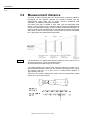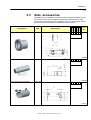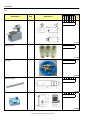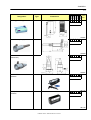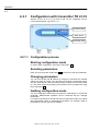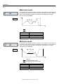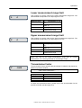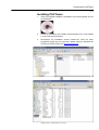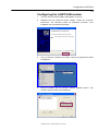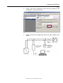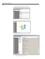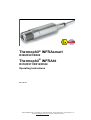
1
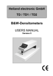
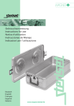
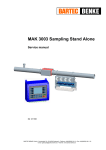
Thermophil® INFRAsmart
R300/R301/R302
Thermophil® INFRAht
R310/R311/R312/R320
Operating Instructions
BA 040120
BARTEC BENKE GmbH y Schulstraße 30 y D-94239 Gotteszell y Phone (09929)-301-0 y Fax (09929)-301-112
E-mail: [email protected] y Internet: www.bartec-benke.de
Contents
I-1
Table of Contents
Contents
Page
1 1.1 1.2 1.3 1.4 1.4.1 1.4.2 System description ______________________________
Properties and fields of use _________________________
Sensor versions __________________________________
Scope of delivery _________________________________
Technical data ___________________________________
Thermophil® INFRAsmart ___________________________
Thermophil® INFRAht ______________________________
1-1 1-1 1-2 1-3 1-4
1-4 1-5
2 2.1 2.2 2.3 2.4 Safety precautions _______________________________
General information _______________________________
Installation location ________________________________
Electrical connection ______________________________
Operating the equipment ___________________________
2-1 2-1
2-1 2-2 2-2 3 3.1 3.2 3.3 3.3.1 Installation _____________________________________ 3-1 Installation location ________________________________ 3-1 Measurement distance _____________________________ 3-2 Aids, accessories _________________________________ 3-3
Safety instructions for the operation of Laserpointer
type R300-101 __________________________________ 3-12 Safety instructions for the utilisation of the IR protection
window Zn-Se type R300-136 (order no. 301954) _______ 3-12
Connection _____________________________________ 3-13 R 300, R 301, R 302 ______________________________ 3-13 Connection via plug ______________________________ 3-13 R 310, R311, R312, R320 _________________________ 3-14 3.3.2 3.4 3.4.1 3.4.1.1 3.4.2 4 4.1 4.2 4.2.1 4.2.1.1 4.2.1.2 4.2.1.3 4.2.1.4 Operation ______________________________________
Measurement operation ____________________________
Error messages __________________________________
Configuration ____________________________________
Configuration with transmitter TR 41-10 ________________
Configuration process _____________________________
Starting configuration mode _________________________
Selecting parameters ______________________________
Changing parameters ______________________________
Quitting configuration mode _________________________
Parameters ______________________________________
Password prompt _________________________________
Emission factor ___________________________________
Damping ________________________________________
Maximum mode __________________________________
Minimum mode ___________________________________
Lower measurement range limit ______________________
Upper measurement range limit ______________________
Transmission factor _______________________________
Ambient temperature alarm _________________________
Fault current _____________________________________
Unit of measurement ______________________________
HART® address __________________________________
Changing the password ____________________________
Default values____________________________________
Starting default value mode _________________________
Setting default values ______________________________
Deleting the password _____________________________
Configuration of the sensor data (not implemented) ______
4-1 4-1 4-1 4-1 4-2 4-2 4-2 4-2 4-2 4-2 4-3 4-3 4-3 4-3 4-4 4-4 4-5 4-5 4-5 4-6 4-6 4-6 4-6 4-7 4-7 4-7 4-7 4-7 4-8 Radiation sensors R3XX BA 040120 18.15/me
Date of issue
15.01.2013 15.01.2013 12.11.2013 27.04.2015 12.11.2013 Contents
I-2
4.2.1.5 4.2.2 4.2.2.1 4.2.2.2 Starting sensor configuration _________________________ 4-8 Selecting a service register __________________________ 4-8 Changing parameters ______________________________ 4-8 Quitting sensor configuration _________________________ 4-8 Meaning of the service registers ______________________ 4-8 Error messages __________________________________ 4-10 Test mode ______________________________________ 4-11 Starting test mode ________________________________ 4-11 Selecting a test __________________________________ 4-11 Quitting test mode ________________________________ 4-11 Outputting current test values _______________________ 4-11 Displaying the infrared sensor temperature _____________ 4-11 Displaying the infrared sensor voltage_________________ 4-11 Configuration with the HART® modem, Type R 300-107 ___ 4-12 Connecting the HART® modem ______________________ 4-12 Software _______________________________________ 4-13 Changing parameters _____________________________ 4-14 5 Configuration PACTware __________________________ 5-1 Installation of the INFRA DTM driver for PACTware ______ 5-1 Installing the isHRT USB interface driver _______________ 5-3 Installing the isHRT FDT driver for PACT-ware ___________ 5-4 Installing PACTware _______________________________ 5-6 Configuring the isHRT USB modem ___________________ 5-8 Configuration PACTware ___________________________ 5-10 6 Maintenance _____________________________________ 6-1 Cleaning kit type R300-128 for pyrometers ______________ 6-1
7 HART® protocol __________________________________ 7-1 8 Additional instructions for use in dust-explosive areas _ 8-1
Annex ___________________________________________ 1 Emission factor ____________________________________ 1 Determining the actual E factor ________________________ 1 Transmission factor _________________________________ 3 Determining the transmission factor ____________________ 3 12.11.2013 15.01.2013 HART® is a registered trademark of the HART Communication Foundation
All rights reserved. Subject to change without prior notice.
No part of this document may be reproduced, processed or distributed
in any form or by any means without the prior written permission of
BARTEC BENKE.
Document:
Revision:
Author:
Translation:
BA 040120
G. Rothe
H. Dean, EXACT GmbH, Mannheim
Radiation sensors R3XX BA 040120 18.15/me
Copyright © 2013 by
BARTEC BENKE GmbH
Schulstraße 30,
D-94239 Gotteszell
Valid from: 01.04
Status: 27.04.2015
January 2004
System description
1-1
1
1.1
Properties
System description
Properties and fields of use
INFRA radiation sensors from the R 3XX series are robust, stationary
measuring sensors that are used in connection with indicating devices,
controllers or recording instruments for contact-free temperature
measurement and temperature monitoring, control or registration.
They enable you to record surface temperatures quickly and reliably even in
situations where traditional contact-based measurement is very difficult, is
only possible to a limited extent or is not actually possible at all. For
instance, they can be used on moving objects, materials with a poor thermal
conductivity, plastic materials and aggressive substances, small components
with a low thermal capacity, current-carrying elements and rails.
The radiation sensor collects the thermal radiation emitted from the
measurement object and uses a lens to concentrate it on the internal
infrared sensor. An optical filter restricts the sensor’s spectral region.
The IR sensor transforms the collected heat energy into an electric signal,
which is then processed in a microprocessor and converted into a linear
current output of 4...20 mA. The influence of the ambient temperature on the
measuring cell and electronics is compensated.
Sensors from the R3XX series are designed using the two-wire technique.
They therefore allow measured values to be transmitted so as to be immune
to interference – even over long distances – and make wiring particularly
simple. Interfering measured value peaks that occur in quick succession can
be suppressed by a variable attenuator.
The size of the measuring field recorded depends on the optics of the sensor
concerned and on the distance between the sensor and the measurement
object (see measuring field diagrams). It is possible to set the emission
factor (which is important for the radiation measurement), the transmission
factor and other parameters.
®
An interface with a HART protocol is used to transmit the measured values
from the sensor and to transmit program information to the sensor.
Fields of use
Thanks to the features mentioned, measurement sensors from the R3XX
series can also be used in places where other measuring systems fail due to
unfavourable ambient conditions. Examples include:
Thermoforming machines for plastics
Extruders for plastics
Calendering lines for plastic films
Coating machines
Glassworking
Metalworking
Monitoring of goods in transit on conveyor belts
Monitoring of plant overheating
Radiation sensors R3XX BA 040120 18.15/me
System description
1-2
1.2
Sensor versions
The radiation sensors are delivered both in a compact form, with a built-in
measuring amplifier (Thermophil® INFRAsmart), and in a two-part form, with
a small radiation sensor and a separate measuring amplifier (Thermophil®
INFRAht). In this case, the radiation sensors and measuring amplifiers are
connected using a heat-resistant cable. The measuring amplifiers available
are types TR 40-10 (in a die-cast aluminium housing) and TR 41-10 (in a
plastic housing, with a display and keypad).
In order to protect the sensor against dust, vapours and other environmental
influences, its measurement opening is sealed with a solid disc or lens. It
can be cleaned without difficulty if it is steamed up or damaged. In the case
of a highly polluted atmosphere it is a good idea to use an air nozzle (see
accessories), which will largely keep the measurement opening clear by
continuously cleaning the air. For the event that the sensor is used at fairly
high ambient temperatures, special cooling jackets with a cooling water
connection are available.
Thermophil® INFRAsmart
R 300 / R301
R 302
Type R300
Sensor with cone 1.7:1, fitted measuring amplifier in IP 65
stainless steel housing
Type R301
Sensor with lens 20:1, fitted measuring amplifier in IP 65
stainless steel housing
Type R302
Sensor with lens 33:1, fitted measuring amplifier in IP 65
stainless steel housing
Radiation sensors R3XX BA 040120 18.15/me
System description
1-3
®
Thermophil INFRAht
TR 40-10
TR 41-10
R 310 / R 311
R 312
R 320
1.3
Type R310
Sensor with cone 1.7:1, separate measuring amplifier
(TR 41-10 or TR 40-10)
Type R311
Sensor with lens 20:1, separate measuring amplifier
(TR 41-10 or TR 40-10)
Type R312
Sensor with lens 33:1, separate measuring amplifier
(TR 41-10 or TR 40-10)
Type R320
Sensor with cone 1.7:1, separate measuring amplifier
(TR 41-10 or TR 40-10)
(Same as R 310, but has the design of the old Type R22)
Scope of delivery
•
Sensor, type as ordered, including measuring amplifier
•
One Operating Instructions manual
•
Work inspection specification
•
Accessories as ordered
Radiation sensors R3XX BA 040120 18.15/me
System description
1-4
1.4
1.4.1
Technical data
Thermophil® INFRAsmart
Measuring range
max. 0...+ 400 °C with R 300
max. 0...+ 2000 °C with R 301/R 302
Spectral response
8 ...14 µm; 2 ... 2,7µm; 4,9 ... 5,5µm; 7,9µm (R300 only)
Emission factor
0.1 to 1, settable externally via the HART® interface
Measuring field
Depending on distance (see “Distance ratio“)
HART® protocol (FSK BELL 202, 1,2 kb/s)
Interface
Functions configurable via HART®-Interface see page 1-6 (Transmitter)
Output (current interface)
Output signal
4...20 mA, linear
Permissible load
≤ 500 Ω for standard version/UH = 24 V
Intrinsically safe circuit Ex ib IIC
max. input voltage
Ui = 28 V
max. input current
Ii = 105 mA
max. power input
Pi = 1,0 W
max. internal capacity
Ci = 12 nF
max. internal inductance
Li = 0,2 mH
Accuracy
Measuring accuracy
≤ 1 % of measuring range (at 23 °C and for emission factor = 1)
Temperature sensitivity
≤ 0.03 %/C°
Response time
t 0.9 = 0.2 s
Ambient conditions
Ambient
Temperature
Max. Surface
Type
Temperature
Class
Temperature
Ex
R30x
-20°C … +60°C
T6
T100 105°C
Permissible operating
0...+70 °C
temperature
Permissible storage temperature -10...+70 °C
Climatic class
KSF according to DIN 40040
Power supply
UH = DC 12...30 V , max. 25 mA, max. residual ripple ≤ 150 mV rms
Connection
4-pole plug connector, degree of protection IP 64
Mechanical data
Type
R 300
R 301
R 302
Housing material
Stainless steel (material no. 1.4301)
Degree of protection
IP 65
Weight
1100 g
1100 g
1460 g
Overall
Radiation sensors R3XX BA 040120 18.15/me
System description
1-5
Dimensions
R 300
R 301
R 302
R 300
R 301
R 302
Distance ratio
1.4.2
Thermophil® INFRAht
Sensors
Measuring range
Overall
Spectral response
Measuring field
Ambient conditions
max. 0...+400 °C with R 310/R 320
max. 0...+2000 °C with R 311/R 312
8 to 14 µm; 2 ... 2.7 µm; 4.9 ... 5.5 µm; 7.9 µm (R 310/R 320 only)
Depending on distance (see "Distance ratio")
Ambient
Temperature Class
Temperature
-20° C…+70°C
T5
R31x, R320
-20° C…+125°C
T4
0…+ 125 °C
-10…+ 125 °C
KKF according to DIN 40040
Type
Ex
Permissible operating temperature
Permissible storage temperature
Climatic class
Mechanical data
Type
Housing material
Degree of protection
Weight
R 310
925 g
R 311
R 312
Stainless steel (material no. 1.4301)
IP 64
925 g
980 g
Radiation sensors R3XX BA 040120 18.15/me
Max. Surface
Temperature
T100 105°C
T100 160°C
R 320
520 g
System description
1-6
Dimensions
R 310 / R311
R 312
R 320
Distance ratio
R 310 / R320
R 311
R 312
Transmitters
For R 310, R 311, R 312, R 320
PT100 for ambient temperature (TR 41-10)
HART® protocol (FSK BELL 202, 1,2 kb/s)
Interface
Functions (configurable via HART® interface, with TR 41-10 also via keyboard)
Unit of measurement
°C or °F
Lower/upper range limits
0…2000 °C (32…3632 °F)
Emission factor
0.1…1
Transmission factor
0.1…1
Ambient temperature alarm
20...70 or 125 °C (68...158 or 257 °F), sensor-dependent
Damping
0...999.9 s
Maximum mode
0...999.9 s
Minimum mode
0...999.9 s
Fault current
3.9...21.5 mA
Fieldbus address
0...15 (0 = point to point, 1…15 = multidrop)
HART® address
0...15 (0 = point to point, 1…15 multidrop)
LC-Display (TR 41-10)
Display
Analogue output
Output signal
4...20 mA, linear
Permissible load
≤ 500 Ω for standard version/UH = 24 V
Accuracy
≤ 1 % of measuring range (at 23 °C and for ε = 1)
Measuring accuracy
R 312: ≤ 1% above 50 °C object temperature, less than 50 °C ≤ 3%
Temperature sensitivity
≤ 0.03 %/C°
Input
Radiation sensors R3XX BA 040120 18.15/me
System description
1-7
Response time
t 0.9 = 0.2 s (without damping)
Power supply
UH = DC 12...30 V, max. 25 mA, residual ripple ≤ 150 mV eff.
Sensor connection
Pin
Signal
Colour
Description
1
–
–
2
–
–
3
R+
rt
Thermistor
4
R–
or
Thermistor
5
U–
sw
Thermopile –
6
U+
bn
Thermopile +
Ambient conditions
Permissible operating temperature
Permissible storage temperature
Climatic class
Mechanical data
Type
Housing material
Weight
Degree of protection
Dimensions
TR 40-10
0...+ 60 °C
-10...+ 70 °C
KSF according to DIN 40040
TR 40-10
Die-cast aluminium
480 g
TR 41-10
Plastic
520 g
IP 65
TR 41-10
Radiation sensors R3XX BA 040120 18.15/me
System description
1-8
Radiation sensors R3XX BA 040120 18.15/me
Safety precautions
2-1
2
Safety precautions
The equipment is produced in line with the regulations currently in force and
only leaves the factory following thorough safety tests to ensure that it is in
perfect condition. Please follow the instructions provided with regard to
installing and operating the equipment.
2.1
2.2
General information
•
Please read the operating instructions prior to installing and starting up
the equipment. Should you have any questions or difficulties, please
contact our service staff.
•
Provide your operating and maintenance staff with detailed instructions
and provide them with all the information they need.
•
The equipment’s internal self-monitoring systems and fault reports do
not replace the safety facilities in the overall system into which the unit is
integrated.
•
Make sure that all regulations relating to the operation of your system
are observed.
•
The equipment must be installed and maintained by qualified technical
personnel.
•
Make sure that the data and operating conditions specified by BARTEC
are observed.
•
For the utilisation of the IR protection window ZnSe, please observe the
safety instructions under chapter 3.3.2.
Installation location
•
When installing the equipment, make sure that you observe the
permissible climatic and temperature conditions in line with the technical
data.
•
If exceptional conditions exist at the installation location, suitable
measures must be taken to protect the equipment (cover, cooling,
heating). Please also look at the accessories we offer with respect to
this.
•
Install the equipment in a location that is not subject to vibrations.
•
Do not choose a location near any equipment that generates
electromagnetic fields (transformers, motors, power lines, magnets,
semiconductor actuators, high-frequency generators and the like).
•
The sensors should be installed in a separate location to protective
circuits wherever possible.
•
If, due to the local circumstances, inductive consumers such as
contactors or solenoid valves are installed nearby, interference in the
contactor coil should be suppressed using an RC circuit. Usually, the
manufacturers of this equipment offer appropriate suppressor
accessories.
Radiation sensors R3XX BA 040120 18.15/me
Safety precautions
2-2
2.3
Electrical connection
•
•
•
2.4
Disclaimer of liability
Before connecting the equipment, check whether the rated voltage
specified on the rating plate corresponds to that available at the
installation location.
The wiring must be carried out by trained specialists.
Lay sensor and signal lines at a sufficient distance from live lines, in
separate cable ducts wherever possible.
Operating the equipment
•
Before switching on the auxiliary power, make sure that the permissible
operating voltage for the equipment is not exceeded.
•
For the power supply, use only a direct current voltage source with a
residual ripple below a maximum of 150 mV rms.
•
It is important that the sensing head does not exceed the permissible
operating temperature during operation.
•
During measurement operation, make sure that the radiation entrance
point is kept clear. The solid disc or the lens must not be clouded by
splashed water or condensed water and must not have any deposits of
dirt.
•
In the event of faults, first determine whether you can rectify them
yourself. If this is not possible, switch off the equipment and send it to
BARTEC for repair, together with a precise specification of the fault.
•
If you discover any signs of damage or destruction to any parts of the
equipment or if safe operation of the equipment cannot be guaranteed
for any other reason, do not start up the equipment or, if already in
operation, shut it down immediately. Notify the local service centre.
Make sure that the equipment cannot be switched on again until the
damage has been remedied.
•
Contact our service specialists if you discover any faults or defects
during operation or if you have cause to doubt whether the equipment is
working properly.
BARTEC GmbH and its vicarious agents only assume liability in the case of
deliberate acts or gross negligence. The extent of liability in such a case is
limited to the value of the order placed with BARTEC GmbH.
BARTEC accepts no liability for any damage resulting from non-observance
of the safety regulations or from non-compliance with the operating
instructions or operating conditions. Secondary damage is excluded from the
liability.
Radiation sensors R3XX BA 040120 18.15/me
Installation
3-1
3
3.1
Installation
Installation location
•
•
•
•
The ambient conditions at the installation location must be within the
permissible temperature and climate ranges. The corresponding data
can be found in Section 1.4 Technical data.
The installation location should be free from vibrations and free of
electromagnetic interference fields. Please also refer to the notes in
Section 2 with respect to this.
When choosing an installation location, please make sure that the
permissible operating temperature for the particular sensor (Sensor
housing temperature) is adhered to (see 1.4).
In the case of a fairly high ambient
temperature, position the sensor in such a
way that it is not exposed to heat
convection from the measurement object
(example 1).
Example 1
•
If such an arrangement is not possible, the sensor must be operated
with an additional cooling jacket (example 2). The cooling jackets are
fitted with a mounting flange (see accessories).
Example 2
Water supply
Heat sink
Sensor
In order to prevent inadmissible heating or damage to the sensor in the
event that the supply of cooling water is cut off, it is also necessary to
monitor the water circulation. BARTEC offers suitable flow control
instruments.
®
The Thermophil INFRAht radiation sensors must be positioned in such a
way that the cable between the radiation sensor and measuring amplifier is
not moved during measurement.
Radiation sensors R3XX BA 040120 18.15/me
Installation
3-2
3.2
Measurement distance
The laws of optics must be taken into account when measuring radiation.
Depending on the distance between the radiation sensors and the
measurement object there will be certain minimum measuring field
diameters – see distance ratio (technical data).
The sensor type that is needed in each case, with the appropriate focal
length, must be determined in accordance with the required measuring field
size at the measurement object and the possible measurement distance. In
order to avoid incorrect measurements, the measurement object must fill the
entire field of view of the sensor lens. The lens field of view must therefore
be no larger than the measurement object itself.
Example
The temperature of a plastic plate with the dimensions 220 x 400 mm is to
be measured using a Type R 300 radiation sensor.
At what distance must the sensor be mounted?
The smallest edge of the plastic plate measures 220 mm in length. For a
measuring field diameter of 220 mm, the measuring field diagram for Type R
300 sensors (see also 1.4.1) gives rise to a measurement distance of
approximately 380 mm.
Therefore, the distance between the sensor and the measurement object
should be no more than 380 mm.
Radiation sensors R3XX BA 040120 18.15/me
Installation
3-3
3.3
Aids, accessories
Depending on the installation conditions and the ambient conditions where
the sensor is used, various installation aids and accessories can be used.
The following overview lists the accessories that can be delivered. Please
feel free to request assistance from BARTEC where required.
Designation
Type
Dimensions
Adapter replacing R20 with R302 R 300-100
R300
R301
R302
R310
R311
R312
R320
For sensor
Order
No.
9
216298
Laser pointer
R 300-101
999999
Cooling jacket for pyrometer
R 300-102
999999
216299
216711
Radiation sensors R3XX BA 040120 18.15/me
Installation
3-4
Designation
Type
Dimensions
R300
R301
R302
R310
R311
R312
R320
For sensor
Order
No.
9
Cooling jacket/air nozzle
Combined, series B
WN 268
Fixed bracket
R 300-105
999 9 99
Adjustable bracket
R 300-106
999 9 99
RS 232/HART®modem incl.
software
R 300-107
U03012268
216975
216976
999 9 99 9
220930
Radiation sensors R3XX BA 040120 18.15/me
Installation
3-5
Designation
Type
Dimensions
R300
R301
R302
R310
R311
R312
R320
For sensor
Test set for testing pyrometers
R30x
R300-110
999
Sensor bracket with air flush
R 300-111
99
Mounting plate for TR40-10
R300-112
Sensor bracket with air flush
(plastics)
R300-113
Sensor bracket with air flush
(without cable protection)
R300-114
Sensor bracket with air flush
plastics (without cable
protection)
R300-115
Order
No.
241933
99
242754
999 9
245891
99
99
246173
999 9 99
247210
999 9 99
247802
Radiation sensors R3XX BA 040120 18.15/me
Installation
3-6
Designation
Type
Dimensions
R300
R301
R302
R310
R311
R312
R320
For Sensor
9
Order
No.
9
Pyrometer slewing device
R300-116
Connecting kit for pyrometer
slewing device
R300-117
R300-116
Cooling water connecting kit for
pyrometer
R300-132
R300-116
Pyrometer protection tube
(stainless steel)
R300-118
Cooling jacket for pyrometer
R300-120
277319
277409
286185
9
9
277420
9
279028
Radiation sensors R3XX BA 040120 18.15/me
Installation
3-7
Designation
Type
Cooling jacket for pyrometer
R300-121
Protective cap for pyrometer
R300-122
Dimensions
R300
R301
R302
R310
R311
R312
R320
For Sensor
Order
No.
9
279027
999 9 99
279030
Sensor bracket with air nozzle R300-123
(aluminium)
9
9
279031
USB/HART-modem incl.
software
R300-125
USB/profibus-modem incl.
software
R300-126
999 9 99 9
281175
999 9 99 9
281176
Radiation sensors R3XX BA 040120 18.15/me
Installation
3-8
Designation
Type
Dimensions
R300
R301
R302
R310
R311
R312
R320
For Sensor
Order
No.
999 9 99 9
Cleaning kit for pyrometer
R300-128
IR silicon slice with seal
e.g. together with R 300-111,
R 300-113
R300-129
99
99
Pyrometer protection tube
D = 50 mm L = 800 mm
R300-130
9
9
Pyrometer protection tube
D = 50 mm L = 300 mm
R300-131
IR safety glass Zn-Se
R300-136
282302
285141
285875
9
9
285876
99
99
301954
Radiation sensors R3XX BA 040120 18.15/me
Installation
3-9
Designation
Mounting nut
Type
Dimensions
R 30000-024
R300
R301
R302
R310
R311
R312
R320
For Sensor
Order
No.
999 9 99
216989
Connection coupling 4-pole,
(axial)
999
Connection coupling
4-pole, (90°)
999
Power supply unit 230 V, output 5906-3
24 V DC in rail-mounting housing
999 9 99 9
U233085
U266182
U8901159063
Power supply unit 230 V, output 5906-4
24 V DC in surface housing
999 9 99 9
U8901159064
Radiation sensors R3XX BA 040120 18.15/me
Installation
3-10
Designation
Extension cable, 4 pole
connector and 4 pole clip
Type
Dimensions
WN 293-5
R300
R301
R302
R310
R311
R312
R320
For Sensor
Order
No.
999
5 m = 314166
8 m = U01110822935
Connection cable, open ends
WN 293-6
999
3 m = U01110322936
6 m = U01110622936
10 m = U01191022936
15 m = 246691
20 m = 290525
30 m = 246596
40 m = 246597
50 m = 246598
60 m = 246600
70 m = 246601
Connection cable Ex,
open ends
WN 293-8
999
3 m = 245550
6 m = 245551
10 m = 245552
15 m = 245546
20 m = 280130
30 m = 288916
60 m = 288933
100 m = 286613
Connection cable R3x,
flexible hose 3 m,
open ends
WN 293-9
999
6 m = 286186
10 m = 286188
15 m = 286189
30 m = 286190
40 m = 286191
50 m = 286192
60 m = 286193
70 m = 286194
Radiation sensors R3XX BA 040120 18.15/me
Installation
3-11
Designation
Type
Connection cable
Connection coupling 90°
WN 293-10
Connection cable Ex
Connection coupling 90°
WN 293-11
Dimensions
R300
R301
R302
R310
R311
R312
R320
For Sensor
Order
No.
9 99
35 m = 294041
9 99
10 m = 302906
60 m = 290261
Radiation sensors R3XX BA 040120 18.15/me
Installation
3-12
3.3.1
Safety instructions for the operation of
Laserpointer type R300-101
To operate the Laserpointer type R300-101, please keep in mind the
following instructions:
The beam emitted by this LASER is strongly bundled.
CAUTION! Do not look into the laser beam or at direct reflexes of reflecting
or polished surfaces - not even by means of optical instruments.
The working area has to be protected by suitable protective shields which
prevent the laser beam from leaving the protected area in an uncontrolled
way.
After the laser beam has crossed the setting range, it has to be blocked and
absorbed by means of a suitable shield.
Do NOT lead the laser beam at eye level.
Attach LASER warning signs at clearly visible locations next to all accesses
to the laser working area.
CAUTION! Use of laser protective goggles is mandatory if you work with an
open laser beam.
The device should only be operated by persons who know these safety
instructions and are familiar with complying to them.
3.3.2
Safety instructions for the utilisation of
the IR protection window Zn-Se type
R300-136 (order no. 301954)
For the utilisation of the IR protection window ZnSe, observe the following
basic instructions:
• The IR protection window contains zinc selenide (ZnSe).
• Avoid any damage to the protection window.
• Damaged filters can cause dust formation. Inhaling or swallowing dust or
splints can cause intoxication. Call a doctor in case of emergency.
• For removing broken protection windows, wear gloves and in urgent
cases a respiratory protection mask and protection goggles.
• Wear gloves to clean the window.
• The protection window should only be replaced by persons familiar with
the safety instructions and observing them.
Radiation sensors R3XX BA 040120 18.15/me
Installation
3-13
3.4
Connection
3.4.1
R 300, R 301, R 302
The sensors can be connected either using a 4-pole plug or using a
connected cable with free ends.
3.4.1.1 Connection via plug
R 300 /301 /302
Plug connector
3
2
4
1
Evaluator
1
ϑ
+
+
4...20 mA
Power
2
Ι
–
Shield
External view /
connector soldering side
When connecting the sensors, make sure that the maximal permissible load
at the sensor output is not exceeded.
The combined resistance of the connected units and cables must not exceed
the maximum value shown in the diagram. This value depends on the
auxiliary power used.
At a supply voltage of 24 V d.c., the maximum permissible load is 500 Ω .
30 V
Auxiliary power (DC)
Example
25 V
20 V
15 V
0
100
200
300
400
500
600
Max. permissible load (Ω)
Radiation sensors R3XX BA 040120 18.15/me
700
800
Installation
3-14
3.4.2
R 310, R311, R312, R320
The sensors are connected to the terminals of the measuring amplifier, Type
TR 40-10 or TR 41-10.
Sensor connection
Pin Signal Colour
1
2
3
R+
red
4
Rorange
5
Ublack
6
U+
brown
–
4...20 mA
Disc
Power
+
Shield
Shield cone
Shield,
14 mm, stripped
Cable gland
Connection to TR 41-10
Radiation sensors R3XX BA 040120 18.15/me
Installation
3-15
–
4...20 mA
+
Shield
Sensor connection
Pin Signal Colour
1
2
3
R+
red
4
Rorange
5
Ublack
6
U+
brown
Disc
Shield
Shield,
14 mm, stripped
Cable gland
Connection to TR 40-10
Radiation sensors R3XX BA 040120 18.15/me
Operation
4-1
4
4.1
Operation
Measurement operation
Once the auxiliary power has been switched on, measurement operation can
be commenced.
Further operation depends on what the sensors are being used for. Please
consult the operating instructions for the connected equipment (e.g. display,
recording instruments, controllers).
Please heed the following during measurement operation:
• The sensor’s measurement opening must be clean. Dust deposits or
moisture may falsify the measured values and must therefore be
removed.
• Precision specifications are only valid for the measurement range
specified on the sensor.
• The radiation sensors must not be subjected to any radiation that is far
above the largest measurement range value for the series in question
(approximately 30 %). It is important that the radiation sensor does not
exceed the permissible operating temperature.
• Please also heed the safety precautions in Section 2.
Error messages
The following error messages can be displayed:
Above upper measurement range limit (“Messbereichsüberschreitung”)
This message is displayed if the value exceeds the preset measurement
range by more than 1 %.
(measurement range = upper range limit – lower range limit)
ERR H
Below lower measurement range limit (”Messbereichsunterschreitung”)
This message is displayed if the value falls short of the preset measurement
range by more than 1 %.
(measurement range = upper range limit – lower range limit)
ERR L
4.2
Configuration
Under various operating conditions it is necessary to select or change
certain settings. Configuration is carried out using an interface with a HART®
protocol.
A HART® programming device or a suitable PC software solution needs to
be used in order to change parameters. The HART® commands are
described in Section 7.
Sensors R 310, R 311, R 312 and R 320 can also be configured using
measured value transmitter TR 41-10.
Radiation sensors R3XX BA 040120 18.15/me
Operation
4-2
4.2.1
Configuration with transmitter TR 41-10
Sensors R 310, R 311, R 312 and R 320 can be configured using a
connected transmitter, Type TR 41-10.
Increase value
Mode button
Decrease value
4.2.1.1 Configuration process
Starting configuration mode
In order to start configuration, press the mode button 3 .
Selecting parameters
Each time you press the mode button 3 , you branch to the next parameter.
Changing parameters
You can use the S and T buttons to increase or decrease the entered
values one value at a time. You can also hold down the respective button,
with the result that the value will change slowly to begin with and then speed
up. The value will be saved when you proceed to the next parameter using
the mode button 3 .
Quitting configuration mode
You quit configuration mode when you press the mode button 3 for the final
parameter. Measurement operation will be continued with the changed
parameters.
If no button is pressed for around 20s during configuration mode, the system
will automatically return to measurement operation. All changes made to
parameters up to then will also be adopted.
Radiation sensors R3XX BA 040120 18.15/me
Operation
4-3
4.2.1.2 Parameters
The following overview lists the configurable parameters in the order in
which they appear on the display when you press the mode button 3 .
Password prompt
C
0
Before you can make any changes to the following parameters, you must
enter the valid password here. The password is changed with the last
parameter in configuration mode.
Display
Minimum value
Maximum value
Increment
Default value
C
0
1999
1
0
Emission factor
E
1.000
The emission factor is a measure of the ability of materials to absorb or emit
infrared radiation.
The value can be between 0.1 and 1.0. A “full radiator”, for instance, has an
emission factor of 1.0, whereas a mirror has an emission factor of 0.1.
An emission factor that is set too high will cause the temperature display to
be too low.
Display
Minimum value
Maximum value
Increment
Default value
E
0.100
1.000
0.001
0.950
Damping
A
0.0
(Calculating the average)
A time over which an average is to be calculated is set here. Each
temperature value that is measured is stored in the memory. Once the fixed
time has passed, the system calculates the average over all values located
in the memory. This damps the temperature display.
The time is set in seconds.
Display
Minimum value
Maximum value
Increment
Default value
A
0.0
999.9
0.1
0.3
Radiation sensors R3XX BA 040120 18.15/me
Operation
4-4
Maximum mode
P
A “hold time” for maximum values is set here. The maximum value that has
occurred in each case is held for the set time and output. If a new maximum
value occurs during the hold time, the hold time will begin all over again.
The time is set in seconds.
0.0
Example
Display
Minimum value
Maximum value
Increment
Default value
P
0.0
999.9
0.1
0.0
Minimum mode
M
A “hold time” for minimum values is set here. The minimum value that has
occurred in each case is held for the set time and output. If a new minimum
value occurs during the hold time, the hold time will begin all over again.
The time is set in seconds.
0.0
Example
th
Hold time
Actual temperature pattern
Temperature pattern that is output
Display
Minimum value
Maximum value
Increment
Default value
M
0.0
999.9
0.1
0.0
Radiation sensors R3XX BA 040120 18.15/me
Operation
4-5
Lower measurement range limit
L
0
This is where you set the value for the lower measurement range limit. The
value defined corresponds to an output signal of 4 mA.
Display
Minimum value
Maximum value
Increment
Default value
L
0
(corresponds to 32
°F)
1250 (corresponds
to
2282 °F)
1 °C (1 °F)
Corresponds to the sensor
measurement range
Upper measurement range limit
U
0
This is where you set the value for the upper measurement range limit. The
value defined corresponds to an output signal of 20 mA.
Display
Minimum value
Maximum value
Increment
Default value
U
0
(corresponds to 32
°F)
1250 (corresponds
to
2282 °F)
1 °C (1 °F)
Corresponds to the sensor
measurement range
If you define the lower measurement range limit as being a temperature
higher than that for the upper measurement range limit, an inverse
characteristic curve will be generated for the analogue output.
Transmission factor
T
1.000
The transmission factor specifies the percentage of radiation that passes an
additional protective window.
Examples 1.000 = 100% transmission (no protective window)
0.800 = 80% transmission
Display
Minimum value
Maximum value
Increment
Default value
T
0.000
1.000
0.001
1.000
To obtain the transmission factor, please refer to the documentation for the
protective window (see also page A-2).
Radiation sensors R3XX BA 040120 18.15/me
Operation
4-6
Ambient temperature alarm
S
65.0
As soon as the inside temperature of the radiation sensor exceeds the
defined value, the temperature display will start flashing and the analogue
output will switch to the programmed state (see fault current).
Display
Minimum value
Maximum value
Increment
Default value
S
20.0 (corresponds to 68 °F)
70.0 or 125.0
(corresponds to 158.0 or 257.0°F)
0.1 °C (0.1 °F)
Sensor-related: 65.0 or 125.0 °C
(corresponds to 149.0 or 257.0 °F)
Fault current
ER
21.0
This is where you define what current is to be output via the analogue output
in the event of a fault.
The current is set in mA.
Display
Minimum value
Maximum value
Increment
Default value
ER
3.9
21.5
0.1
21.0
Unit of measurement
D
°C
You can choose °C or °F as the unit of measurement for the temperature
display.
Display
Minimum value
Maximum value
Default value
D
°C
°F
°C
HART® address
HA
0
You can operate up to 15 transmitters in parallel (multidrop mode). Each
sensor (transmitter) then requires an individual address between 1 and 15.
The address must be set to 0 if you want to operate the transmitter in
standalone operation (point-to-point operation).
Display
Minimum value
Maximum value
Increment
Default value
HA
0
15
1
0
Radiation sensors R3XX BA 040120 18.15/me
Operation
4-7
Changing the password
C
Once you have started configuration mode and entered the valid password,
this menu for changing the password will appear.
0
Display
Minimum value
Maximum value
Increment
Default value
C
0
1999
1
Current password
4.2.1.3 Default values
You can reset the equipment to the factory settings and delete the
password.
Starting default value mode
DEFAULT
Keep the S button pressed down and additionally press the 3 button for at
least 2 seconds. Then let go of the two buttons. The display should then
appear as in the screenshot on the left.
Setting default values
ORG 0
After starting default value mode, press the 3 button. The display will then
appear as in the screenshot on the left.
You can use the S and T buttons to increase or decrease the value
displayed.
Set one of the following values:
32 t The factory settings will be used until the equipment is switched off.
34 t The factory settings will be used permanently.
Display
Minimum value
Maximum value
Increment
Default value
ORG
0
99
1
0
Deleting the password
CODE 0
After starting default value mode, press the 3 button twice. The display will
then appear as in the screenshot on the left.
You can use the S and T buttons to increase or decrease the value
displayed.
Set the following value:
32 t The user password (code) will be set to 0.
Display
Minimum value
Maximum value
Increment
Default value
CODE
0
99
1
0
Radiation sensors R3XX BA 040120 18.15/me
Operation
4-8
4.2.1.4 Configuration of the sensor data
(not implemented)
After you have exchanged a sensor you need to enter the associated
configuration data. You can find the data in the relevant sensor
documentation.
Before you can enter values you must first enter the valid password (see
Section 4.2.1.2, Password prompt).
Starting sensor configuration
SERVICE
Keep the S and T buttons pressed down and additionally press the 3
button for at least 2 seconds. Then let go of the 3 first. The display should
then appear as in the screenshot on the left.
Selecting a service register
S0
0
Each time you press the mode button 3 , you branch to the next service
register. The service register in question will appear on the display (S0…S9).
Changing parameters
You can use the S and T buttons to increase or decrease the entered
values one value at a time. You can also hold down the respective button,
with the result that the value will change slowly to begin with and then speed
up. The value will be saved when you proceed to the next register using the
mode button 3 .
Quitting sensor configuration
You quit sensor configuration when you press the mode button 3 for the
final service register – assuming that no error message is displayed (see
page 4-10 ).
If no button is pressed for around 20s during sensor configuration, the
system will automatically end configuration and return to measurement
operation.
Meaning of the service registers
Service register 0
Display
Minimum value
Maximum value
Increment
Default value
Meaning
S0
0
65535
1
0
Configuration word
Service register 1
Display
Minimum value
Maximum value
Increment
Default value
Meaning
S1
0
65535
1
0
Thermistor offset
Radiation sensors R3XX BA 040120 18.15/me
Operation
4-9
Service register 2
Display
Minimum value
Maximum value
Increment
Default value
Meaning
S2
0
65535
1
0
Thermistor gradient
Service register 3
Display
Minimum value
Maximum value
Increment
Default value
Meaning
S3
0
65535
1
0
Used
Service register 4
Display
Minimum value
Maximum value
Increment
Default value
Meaning
S4
0
65535
1
0
Cell gradient (part 1)
Service register 5
Display
Minimum value
Maximum value
Increment
Default value
Meaning
S5
0
65535
1
0
Cell gradient (part 2)
Service register 6
Display
Minimum value
Maximum value
Increment
Default value
Meaning
S6
0
65535
1
0
Used
Service register 7
Display
Minimum value
Maximum value
Increment
Default value
Meaning
S7
0
65535
1
0
Used
Radiation sensors R3XX BA 040120 18.15/me
Operation
4-10
Service register 8
Display
Minimum value
Maximum value
Increment
Default value
Meaning
S8
0
65535
1
0
Reserve
Service register 9
Display
Minimum value
Maximum value
Increment
Default value
Meaning
S9
0
65535
1
0
Checksum
Error messages
If any errors have occurred, they will be displayed once you have left the last
service register (S9). Pressing the mode button 3 takes you back to the
beginning of the menu (S0). If a checksum error has occurred, you can
make any necessary corrections in the service registers.
If an error is reported, you can only quit the sensor configuration by not
pressing any button for around 20 seconds or by switching off the unit.
The following messages may be output:
ERR CHK1
ERR CHK2
Incorrect checksum
Check the settings in the service registers and
change them as appropriate.
EEPROM access incorrect
Please contact your service centre.
Radiation sensors R3XX BA 040120 18.15/me
Operation
4-11
4.2.1.5 Test mode
In test mode, you can test downstream equipment by outputting defined
current values.
Starting test mode
TEST
Keep the T button pressed down and additionally press the 3 button for at
least 2 seconds. Then let go of the two buttons. The display should then
appear as in the screenshot on the left.
Selecting a test
Each time you press the mode button 3 , you branch to the next test. The
test in question will appear on the display (T1…T3).
Quitting test mode
You quit test mode when you press the mode button 3 for the final test
(T3).
If no button is pressed for around 20s during test mode, the system will
automatically quit the mode and return to measurement operation.
Outputting current test values
T1 I-OUT
After starting test value mode, press the 3 button. The display will then
appear as in the screenshot on the left.
You can use the S and T buttons to select the current value to be output.
You can set the following values:
Display
T 1 I-OUT
T 1 4 MA
T 1 5 MA
T 1 10 MA
T 1 12 MA
T 1 16 MA
T 1 20 MA
T 1 21 MA
Test value
Current measured value
4 mA
5 mA
10 mA
12 mA
16 mA
20 mA
21 mA
Displaying the infrared sensor temperature
O
T2 25.2 C
After starting test value mode, press the 3 button twice. The display will
then appear something like in the screenshot on the left (example).
The last temperature determined will be displayed in °C.
Displaying the infrared sensor voltage
T3 22.1234
After starting test value mode, press the 3 button three times. The display
will then appear something like in the screenshot on the left (example).
The last voltage determined will be displayed in mV (temperaturecompensated value).
Radiation sensors R3XX BA 040120 18.15/me
Operation
4-12
4.2.2
Configuration with the HART® modem,
Type R 300-107
In the case of radiation sensors not operated with a transmitter that has a
display, configuration is carried out using the R 300-107 HART® modem and
a PC software solution that is delivered with the modem.
4.2.2.1 Connecting the HART® modem
Connect the modem as described in the documentation provided (see
diagram).
Radiation sensors R3XX BA 040120 18.15/me
Operation
4-13
4.2.2.2 Software
• Install the HART infrared configuration software that is delivered together
with the HART® modem.
• Start the HART infrared configuration software.
Set the interface parameters as shown in the diagram below, choosing the
interface that is connected to the HART® modem.
• Click the [Verbindung_aufbauen] (Set up connection) button.
Radiation sensors R3XX BA 040120 18.15/me
Operation
4-14
Changing parameters
Once the connection has been set up, the parameters of the connected
HART® unit will be read and displayed.
You can enter the configuration data in the “Temperatur Prozess
Einstellungen” (temperature process settings) section (see Section 4.2.1.2).
Radiation sensors R3XX BA 040120 18.15/me
Configuration PACTware
5-1
5
Configuration PACTware
The following installation was carried out on a system running Windows XP
Professional Version 2002 SP3.
Installation of the INFRA DTM driver for
PACTware
1.
Insert the supplied installation CD-ROM for the R 300 software into the
CD-ROM drive.
2.
Cancel the installation of the HART Infraconfigurator, as it is not needed
in conjunction with the DTM driver.
3.
Start the setup programme (setup.exe) for INFRA DTM.
4.
The installation commences → follow the on-screen instructions.
Radiation sensors R3XX BA 040120 18.15/me
Configuration PACTware
5-2
5.
Installation steps:
Radiation sensors R3XX BA 040120 18.15/me
Configuration PACTware
5-3
Installing the isHRT USB interface driver
1.
Please refer to the isHRT USB user manual.
2.
The driver software must be installed before connecting the device!
3.
Insert the supplied installation CD-ROM for the isHRT driver software
into the CD-ROM drive.
4.
If the installation does not start automatically, call up the setup
programme for isHRT Multidriver.
5.
The installation commences → follow the on-screen instructions:
Radiation sensors R3XX BA 040120 18.15/me
Configuration PACTware
5-4
6.
Installation steps:
Radiation sensors R3XX BA 040120 18.15/me
Configuration PACTware
5-5
Installing the isHRT FDT driver for PACTware
1.
Please refer to the isHRT FDT user manual.
2.
Insert the supplied installation CD-ROM for the isHRT driver software
into the CD-ROM drive.
3.
Start the setup programme for isHRT FDT Setup.
4.
The installation commences → follow the on-screen instructions.
5.
Installation steps:
Radiation sensors R3XX BA 040120 18.15/me
Configuration PACTware
5-6
Enter the CD code supplied:
→ Supply your company information
(e.g. company, city)
→ CD code as supplied
(e.g. 1111-2222-AAAA-3333-BB44)
Radiation sensors R3XX BA 040120 18.15/me
Configuration PACTware
5-7
Installing PACTware
1.
Insert the supplied installation CD-ROM for the R 300 software into the
CD-ROM drive.
2.
Cancel the installation of the HART Infraconfigurator, as it is not needed
in conjunction with PACTware.
3.
Decompress the installation archive pw35ics.zip. Start the setup
programme (setup.exe) for PACTware. Where required, download the
current PACTware version from www.pactware.com.
Radiation sensors R3XX BA 040120 18.15/me
Configuration PACTware
5-8
4.
The installation commences → follow the on-screen instructions.
Several programme parts are installed.
5.
Installation steps:
Radiation sensors R3XX BA 040120 18.15/me
Configuration PACTware
5-9
Configuring the isHRT USB modem
1.
You can now connect the isHRT USB modem to your PC.
2.
Windows will now install the driver modem. Follow the on-screen
instructions. The following should be displayed on-screen, once
installation has concluded successfully.
3.
You now need to configure the modem. Call up the programme isHRT
Configurator.
4.
Find the modem with the function 'Search attached device'. The
modem's serial number will be displayed.
Radiation sensors R3XX BA 040120 18.15/me
Configuration PACTware
5-10
Configuration PACTware
1.
Start the PACTware programme.
2.
Call up the menu point Tools → Manage Device Catalogue. The device
entries 'BARTEC Thermophil DTM' and 'isHART USB v2' must be
displayed there. Should these entries not be visible, try locating the
driver with 'Update Device Catalogue'.
Radiation sensors R3XX BA 040120 18.15/me
Configuration PACTware
5-11
3.
Create a new device configuration. Press OK when prompted to add
the BARTEC Thermophil DTM driver.
4.
Supply the sensor with voltage and connect the HART modem to the
sensor.
Radiation sensors R3XX BA 040120 18.15/me
Configuration PACTware
5-12
5.
Read the device data from the sensor.
Radiation sensors R3XX BA 040120 18.15/me
Maintenance
6-1
6
Maintenance
Cleaning kit type R300-128 for pyrometers
BARTEC pyrometers are very durable and almost maintenance-free.
Maintenance is restricted to checking and cleaning the optics. If it is cleaned
regularly and carefully, the high reliability of the measuring system can be
preserved and guaranteed.
Arranged in a stable and convenient carrying case, the cleaning kit contains
all facilities to carry out the cleaning quickly and thoroughly and without any
risk for the process and the sensor.
If required, the components contained in the kit can be re-ordered
individually.
Use the vacuum brush to remove
loose dirt and dust particles. Dust that
is raised can be sucked off by means
of the rubber bellows.
Use the bellows to remove dirt
particles even from areas of the optics
that are difficult to access for the
brush.
To access deeper areas, you can
attach an extension nozzle.
Radiation sensors R3XX BA 040120 18.15/me
Maintenance
6-2
The air stream can be emitted either
continuously or as a strong air blast. Change the
position of the air outlet nozzle accordingly.
Air stream
Air blast (press hard!)
Use the cleaning spray if there are deposits
or hard-sticking dirt particles.
Let the fluid take effect for a short time.
With a cleaning tissue and by applying only
little pressure, carefully wipe off the dissolved
dirt.
Never wipe across the lens before solid
particles have been removed or dissolved.
For the utilisation of the IR protection window
ZnSe, please observe the safety instructions
under chapter 3.3.2.
Ordering details
Designation
Cleaning kit type R300-128 complete
Cleaning fluid PUROSOL
Cleaning tissues PREMATEX
Vacuum brush
Bellows
Radiation sensors R3XX BA 040120 18.15/me
Order number
282302
282366
282367
282368
282369
HART® protocol
7-1
7
HART® protocol
The following table contains an overview of the relevant HART® commands
in HART® Version 7.
No and function
0
Read unique identifier
1
Read primary variable
2
Read current and percent of range
3
Read current and four (predefined)
dynamic variables
6
Write polling address
8
Read dynamic variable
configuration
Read unique ident. Associated with
tag
Read message
Read tag, descriptor, date
Read PV sensor information
Read output information
Read final assembly number
Write message
Only stored in RAM!
Write tag, descriptor, date
Write final assembly number
Only stored in RAM!
11
12
13
14
15
16
17
18
19
Data in the instruction
Data in the reply
byte
HART-address
byte
Loop Current Mode
(not implemented)
Byte
Range unit code
Float
PV
Float
Current
Float
Percent of range
Float
Current (present output current)
byte
Range unit code
float
PV (object temperature)
byte
Range unit code
float
SV (present housing temperature
UT)
byte
Range unit code
float
TV (object temperature prior to
damping)
byte
Range unit code
float
VV (object temperature prior to
min/max value)
byte
HART-address
Byte
Loop Current Mode
(not implemented)
Radiation sensors R3XX BA 040120 18.15/me
HART® protocol
7-2
No and function
34
Write damping value for the PV
35
Write range values for the PV
38
40
128
Reset "config changed" flag
Enter/exit fixed current mode loop
test (fix the analogue current at
specified value
Read emissivity
129
Write emissivity
130
Read reflectivity
131
Write reflectivity
132
Read transmissivity
133
Write transmissivity
134
Read error current
135
Write error current
136
Read max/min hold time
137
Write max/min hold time
138
Read alarm values
139
Write alarm values
144
Special command (read only)
see description
145
Special command
see description
146
Read factory settings and write
them to EEPROM
Data in the instruction
float
average value 0…999.9 s
byte
range unit code
float
upper range value (MBE)
float
lower range value (MBA)
Data in the reply
float
average value 0…999.9 s
byte
range unit code
float
upper range value (MBE)
float
lower range value (MBA)
float
current
(0 = exit fixed current mode)
float
current
float
Emissivity 0.100…1.000
float
Reflectivity 0.100…1.000
float
Transmissivity 0.100…1.000
float
error current
float
Max hold time 0.0 … 999.9 s
float
Min hold time 0.0 … 999.9 s
float
Alarm value [°C]
float
Value 1
float
Value 2
float
Value 1
float
Value 2
int
Password
Password [32] >only RAM
Password [34] >EEPROM
Radiation sensors R3XX BA 040120 18.15/me
float
Emissivity
float
Emissivity
float
Reflectivity
float
Reflectivity
float
Transmissivity
float
Transmissivity
float
error current [mA]
float
error current [mA]
float
Max hold time [s]
float
Min hold time [s]
float
Max hold time [s]
float
Min hold time [s]
float
Alarm value [°C]
float
Alarm value [°C]
float
Value 1
float
Value 2
float
Value 1
float
Value 2
int
Success message (0 = error ; 1 =
ok)
HART® protocol
7-3
No and function
148 Read device data
Data in the instruction
Data in the reply
long
ANr
char[15]
Type
int
Software version
Description of command 144
Command
144
144
144
144
144
144
144
144
144
144
Data in the instruction
float
float
0
Unimportant
Display service register no. 0
1
Unimportant
Display service register no. 1
2
Unimportant
Display service register no. 2
3
Unimportant
Display service register no. 3
4
Unimportant
Display service register no. 4
5
Unimportant
Display service register no. 5
6
Unimportant
Display service register no. 6
7
Unimportant
Display service register no. 7
8
Unimportant
Display service register no. 8
9
Unimportant
Display service register no. 9
Radiation sensors R3XX BA 040120 18.15/me
Data in the reply
float
float
0
Content of service register
1
Content of service register
2
Content of service register
3
Content of service register
4
Content of service register
5
Content of service register
6
Content of service register
7
Content of service register
8
Content of service register
9
Content of service register
HART® protocol
7-4
Description of command 145
Command
145
145
145
145
145
145
145
145
145
145
145
145
Data in the instruction
float
float
0
Value
Describe service register no. 0
1
Value [0-65536]
Describe service register no. 1
2
Value [0-65536]
Describe service register no. 2
3
Value [0-65536]
Describe service register no. 3
4
Value [0-65536]
Describe service register no. 4
5
Value [0-65536]
Describe service register no. 5
6
Value [0-65536]
Describe service register no. 6
7
Value [0-65536]
Describe service register no. 7
8
Value [0-65536]
Describe service register no. 8
9
Value [0-65536]
Describe service register no. 9
10
Value [0-65536]
Check sensor data and write to EEPROM
Password [34]
146
Value [0…65536]
Read factory settings and write them to EEPROM
Password [32] >only RAM
Password [34] >EEPROM
Radiation sensors R3XX BA 040120 18.15/me
Data in the reply
float
float
0
Content of service register
1
Content of service register
2
Content of service register
3
Content of service register
4
Content of service register
5
Content of service register
6
Content of service register
7
Content of service register
8
Content of service register
9
Content of service register
Upon error:
999990 = checksum incorrect
10
Content of service register
Upon error:
999990 = checksum incorrect
999991 = errors when writing to
EEPROM
146
Return value
0 = error
1 = ok
Instruction
8-1
8
Additional instructions for
use in dust-explosive areas
This supplementary chapter provides additional instructions for the safe
usage of
•
•
Thermophil® INFRAsmart type R300 / R301 / R302 and
Thermophil® INFRAht Typ R310 / R311 / R312 / R320 with measuring
amplifier TR40-10
in potentially explosive areas.
General information
Installation2), 3)
•
The following details on the type plate have to meet the requirements of
the Ex field of application on site: device group, category, temperature
class, maximum surface temperature
(II 2 G Ex ib IIC T6…T4, II 2 D Ex ib IIC T100 105°C / 160°C)
•
Make sure there is no potentially explosive atmosphere during
installation.
•
Installation and start-up may only be carried out by an appropriately
qualified electrician. The electrical connection is carried out via the
respective cable or the respective connection assembly. For
Thermophil® INFRAsmart with connection via plug, only use the
appropriate connectors or connection cables which guarantee a
protection type of at least IP 64 (see “accessories”). The connectors
have to be mounted correctly.
•
The intrinsically safe cables and wires leading to the device and
between the measuring head and the measuring amplifier have to be
designated as intrinsically safe. This can be done by means of an
appropriate label or by a light-blue wrapping.
•
Check the compatibility of the housing sealing materials to the mediums
existing at the place of application by taking into consideration the
ambient temperature (see resistance).
•
Do not open the housing with the exception of the measurement
amplifier type TR40-10!
•
Avoid or, if this is not possible, safely discharge any electrostatic
charges. It may be necessary to earth the metallic housing and any
parts in the environment. If a purge air facility is used at the optical
system, pay attention to the risk of a separation of charges caused by
flowing air polluted by dust.
Radiation sensors R3XX BA 040120 18.15/me
Instruction
8-2
•
Caution! Before working with circuits and before opening the connection
assembly within a potentially explosive area, switch off the power supply
of the circuits. Within a potentially explosive area, only the tools and
measurement equipment approved for this purpose may be used.
Maintenance
•
Dust deposits should be restricted or completely prevented if possible. In
order to prevent any unusual temperature rise at the dust-proof housing
caused by excessive dust deposits, clean the housing regularly.
Ambient conditions
The maximum surface temperature or the temperature class depends on
• the type
• the maximum ambient temperature
Type
Ambient temperature
R300, R301, R302,
TR40-10
-20°C … +60°C
-20°C … +70°C
-20°C … +60°C
-20°C … +70°C
-20°C … +125°C
R310, R311; R312,
R320
Temperatur
e class IIG
T6
T5
T6
T5
T4
Maximum surface
temperature II D1)
T100 105°C
T100 160°C
Safety instructions
•
Potentially explosive areas are defined under atmospheric conditions
within a temperature range from –20°C to +60°C and a pressure range
between 0.8 bar and 1.1 bar. Any operation outside these limits may
result in additional restrictions.
•
Make sure that any potential dust deposits do not exceed a maximum
thickness of 100 mm.
Resistance
The following plastic materials are used as sealing materials for the housing:
4)
• polybutylenterephthalate (PBT)
• viton (O-rings)
Before the application, the operator has to check the resistance of these
plastic materials to the mediums existing at the place of application by also
taking into consideration the climatic ambient conditions at the place of
application (temperature, humidity..).
Radiation sensors R3XX BA 040120 18.15/me
Instruction
8-3
Technical data
At the (+) and (-) connections of the auxiliary energy (supply / signal circuit)
the device has to be supplied with a certified intrinsically safe Ex ib IIC circuit
or with a certified intrinsically safe EEx ia IIC circuit with the following
maximum values:
Maximum input voltage
Maximum input current
Maximum input power
Ui 28 V
Ii 105 mA
Pi 1,0 W
The maximum internal capacity and inductance including a cable of up to 15
m are as follows:
Maximum internal capacity
Maximum internal inductance
Ci 12 nF
Li 0,2mH
Note 1: The internal capacity between the intrinsically safe supply /signal
circuit and the housing is 12 nF. Any potential differences between the
intrinsically safe supply /signal circuit and the housing have to be avoided. If
required, the installation location of the device and / or the device as well as
the environment of the cable routing have to be integrated in the potential
compensation.
Note 2: The mentioned values are safety-related maximum values. The
operating values / nominal values for tension are UH = DC 12 V ... DC 24 V
and for maximal current consumption = 25 mA.
Typ
R300,
R301,
R302
Connections of supply / signal circuit
Pin 2 (-)
Pin 1(+)
blue (+)
brown (-)
TR40-10
l-(-)
l+(+)
1) The details on the maximum surface temperature on the rating plate are based on measurements under
normal ambient and installation conditions. Changes of these conditions (e.g. constricted conditions of
installation) may have considerable effects on the temperature.
2) see also EN 50281-1-2
3) see also EN 60079-14
4) male / female connector of the connection assembly (auxiliary energy)
Radiation sensors R3XX BA 040120 18.15/me
Instruction
8-4
Radiation sensors R3XX BA 040120 18.15/me
Annex
A-1
Annex
Emission factor
If you want to measure the temperature of an object without contact, you
need to know the emission degree “E” and include it in the measurements.
The calibration basis for IR temperature measuring units and control units is
the black body with the emission degree E = 1.
Determining the actual E factor
The emission factor depends on the material and the condition of its surface.
Theoretical values are specified in the corresponding literature.
Due to the fact that the E factor also depends on the wavelength, the
temperature and the direction in which the radiation is emitted, however, the
values listed in the table can only be used as rough approximates, for
instance for project planning. It can generally be said that raw, matt or
oxidized surfaces have a higher E factor than shiny materials.
Table showing the emission factor E at room temperature
Surface
Asbestos slate
Bakelite varnish
Lead, oxidized
Chrome nickel, oxidized 20 Ni 25 Cr 55 Fe
Chrome nickel, oxidized 20 Ni 25 Cr
Chrome nickel, oxidized 60 Ni 12 Cr 28 Fe
Roofing felt
Ice, smooth, water layer
Ice, rough surface
Enamel, white / porcelain
Iron, oxidized
Iron, oxidized
Iron, rusty
Iron, rolling skin
Plaster
Glass
Graphite
Rubber, soft, grey
Rubber, hard
Skin, dry
Radiator varnish, oil paint
Wood (beech)
Plastics (PVC, PTFE, PE at thicknesses of 0.4 mm
or more)
Copper, oxidized
Matt varnish, e.g. 3 M 1020
Brass, oxidized
Paper
Steel, raw
Clay, baked
Brick, mortar, plaster
Radiation sensors R3XX BA 040120 18.15/me
Temperature (°C)
20
80
200
200
500
270
20
0
0
20
100
500
25
20
20
20...90
20
25
25
30
85
20...70
20...150
20...130
20...120
200...600
20
40...400
70
20
E factor
0.93
0.935
0.63
0.90
0.97
0.89
0.93
0.966
0.985
0.9...0.92
0.74
0.84
0.85
0.77
0.85
0.94
0.45
0.86...0.94
0.955
0.96
0.925
0.915
0.91
0.77
0.96
0.60
0.85
0.79...0.94
0.91
0.93
Annex
A-2
In practice, it is a good idea to verify the E factor once by taking a
comparison measurement. Various measurement procedures may be
suitable depending on the circumstances.
Drill hole method:
A hole with a depth of 2 - 3 mm is drilled into the measurement object and
an immersion measurement is taken in the hole using a low-mass sensor
(semiconductor or thermal element, ∅ 0.5 mm). Then, the temperature is
measured using a radiation sensor and the E factor is adjusted until the “true
temperature” determined beforehand is displayed.
Emission conversion:
The surface of the measurement object is covered with a substance for
which the E factor is known (e.g. black 3M "Velvet Coating 2010" matt
varnish; E 0.93).
You can also apply this method if you want to measure the surface
temperature of shiny rollers (E 0.2). Usually, it is possible to apply the
adhesive matt varnish at the edge of this isothermally heated calendar.
If this is not possible, or if the temperature distribution across the roller
length is irregular, you should use what is called an emission converter, like
the one shown in the picture. In the process, a thin black Teflon strip (E
0.95) stretched on a frame makes contact with the roller and is measured
using the radiation sensor.
Taking a measurement on a slow-running roller with the aid of the emission
converter:
Teflon strip
Contact-based measurement:
Measure the surface temperature of the measurement object, for instance
using a low-mass thermal spiral or band element. This method cannot be
used for substances with a very poor thermal conductivity, though.
Convection measurement:
If it is not possible to take a contact-based measurement because the
measurement object is moving extremely quickly (as may be the case for a
calendar or roller, for instance), a roller sensor that works based on the
convection principle can be used. The large time constant of the sensor
must be taken into account but it does not interfere with this one-off
measurement.
Test method:
If you blacken part of a material sample (e.g. with Velvet Coating from 3M)
and then, for instance, heat it up in a climatic test cabinet, you can take a
differential measurement to establish the exact value of the emission factor.
In other words, with the E factor set to 1, you take a measurement on the
blackened part and then take a measurement on the part that has not been
blackened. By changing the E factor, you set the same display as before and
can now read the E factor on the E regulator.
Radiation sensors R3XX BA 040120 18.15/me
Annex
A-3
Transmission factor
The transmission factor specifies the percentage of radiation that passes an
additional protective window.
If you do not have the details of the transmission factor for the protective
window used, you can work it out yourself.
Determining the transmission factor
•
Measure the temperature of the measurement object with the
sensing head, without using the protective window. When you do
this, make sure that the correct emission factor is set.
•
In the configuration, enter 1.000 as the transmission factor (see
page 4-5 Transmission factor).
•
Use the protective window.
•
Change the transmission factor in the configuration and repeat the
measurement. Compare the measured temperature with the
temperature that was measured without the protective window.
•
Keep repeating this process until the temperature displayed is the
same as that for the measurement without the protective window.
Radiation sensors R3XX BA 040120 18.15/me
***
Radiation sensors R3XX BA 040120 18.15/me