1
Item #3
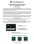
nCompass Control Module (loop controls ordered separately)
CM Order Matrix #
(note 3)
1
2
3
4
1. Control Module (CM) Application Software (loop control type)
0: FD42:
1: FD10:
2: FD30:
3: HWSL:
4: HWDL:
5: WTSD:
6: WTPM:
7: DHPL:
8: YKGS:
9: Special
CM software for FDC P41 / B42 Series
CM software for FDC 100 / B41 Series
CM software for FDC 300 Series
(note 1)
CM software for Honeywell 2500/3200
(note 1)
CM software for Honeywell 3500
(note 2)
CM software for Watlow SD
CM software for Watlow PM
CM software for Danaher West/Partlow Plus
CM software for Yokogawa UT Green Series
2. Optional Serial Communication (DIN Rail Mount – plug into CM)
5
6
7
6. Optional Monitor Inputs (serial connection to CM)
0: None
1: IO-8TCS:
2: IO-6RTD:
3: IO-8AIIS:
4: IO-8AIVS:
(8-thermocouple input module - isolated)
(6-RTD input module)
(8- input module 0-20 / 4-20mA - isolated)
(8-analog input 0-10 / 2-10Vdc—isolated)
Combination Monitor Input Modules (maximum of 2 & 15 points)
A: Item 1 / qty 2
F: Items 1 & 3
B: Item 2 / qty 2
G: Items 1 & 4
C: Item 3 / qty 2
H: Items 2 & 3
D: Item 4 / qty 2
I: Items 2 & 4
E: Items 1 & 2
J: Items 3 & 4
Note: Maximum of 2 monitor input cards monitoring a maximum of 15
monitor inputs.
0: None
1: FC5A-SIF4
2: FC5A-SIF2
(RS485 Modbus RTU port (slave))* (port 3)
(RS232 port for Barcode Reader) ** (port 4)
Note: If Item 2 is specified, Item 1 is included and must be installed
for proper operation of the barcode reader.
7. Special
0: None
*RS485 Modbus RTU port allows R/W access by FDC Envision & 3rd party software.
**Bar Code Reader input is compatible for serial based barcode readers.
Note 1: Maximum of 2 monitor input cards monitoring a maximum of 15
monitor card inputs. With specific CM software, the loop control’s input #2
may be configured as a monitor point. System maximum of 15 monitor
points made up of loop control input #2, inputs of monitor cards or
combination of both.
3. Optional Digital Inputs (DIN Rail Mount – plug into CM)
0: None
1: FC4A-N08B1: (8-digital input card (24Vdc))
2: FC4A-N08A11: (8-digital input card (120Vac))
Note 2: Dual loop HW3500 is limited to 1 controller maximum (2 loops).
Note: The above optional digital inputs (DI) are in addition to the eight 24Vdc digital
inputs that are standard on the CM; system maximum of 16 digital inputs.
Note 3: CM-XXXXXXX includes the additional standard components:
4. Optional Digital Outputs (DIN Rail Mount – plug into CM)
0: None
1: FC4A-T08S1
2: FC4A-R081
Part #: FC4A-HPC3
(Note A)
Comms Card (RS485 comms to loop controls and monitor cards)
(8-digital output– TTL 24Vdc (source))*
(8-digital output - Relay (240Vac 2-amps)
Part #: FC5A-D16RA1-v2.32
Control Module with 8 Digital Inputs (DI) and 8 Digital Outputs (DO)
Note: The above optional digital outputs (DO) are in addition to the 8 DO that are
standard on the CPU (6 relay & 2 TTL 24Vdc); maximum of 16 DO.
Part #: FC4A-PT1
(Note B)
Real Time Clock module
5. Optional Analog I/O (DIN Rail Mount – plug into CM)
Part #: FC4A-PM64
(Note B)
Memory Module
0: None
1: One AI/O card
2: Two AI/O cards
Note A: FC4A-HPC3 must be plugged into the FC5A-D16RA1 control
module during installation as described in the manual.
FC4A-L03A1 (4-20mA or 0-10Vdc IO)
FC4A-L03A1 (4-20mA or 0-10Vdc IO)
Note: Each I/O card has qty 2 Remote Setpoint input and quantity 1 Retransmission
output configurable for PV, SP or Percent Output.
RoHS Compliant
Note B: The FC4A-PT1 and FC4A-PM64 modules are assembled and
contained within the FC5A-D16R1 Control Module.
All other CM (Control Module) options are packaged separately and like the
FC4A-HPC3 must be plugged into the FC5A-D16RA1 bus as described in
the manuals. The exception is the Monitor Card(s) which are not part of the
FC5A-D16RA1 bus and have separate power supply and RS485
communication wiring. The Monitor Card serial RS485 is wired to the
FC4A-HPC32 board along with any loop controls.
P.O. Box 1196
888.751.5444 Sales
Bridgeview, IL 60455
888.307.8014 Fax
Technical Support: 866.342.5332
http://www.futuredesigncontrols.com
FDC nCompass - CM Matrix November 2013
Page 3 of 5