1
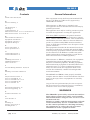
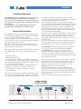
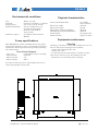
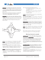
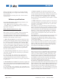
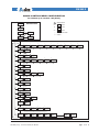
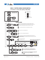
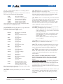
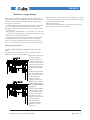
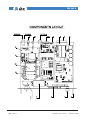
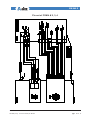
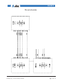
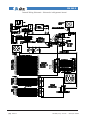
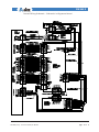
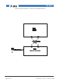
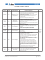
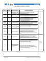
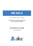
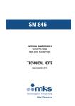
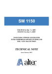
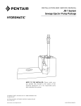
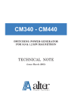
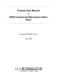
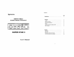
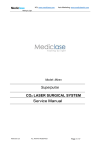
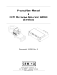
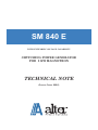
SM 840 E WITH EXTENDED VOLTAGE CAPABILITY SWITCHING POWER GENERATOR FOR 2 KW MAGNETRON TECHNICAL NOTE (Issue June 2002) SM 840 E Dichiarazione CE di Conformità CE Declaration of Conformity Nome del costruttore: Manufacturer’s Name: ALTER s.r.l Indirizzo del costruttore: Manufacturer’s Address: Via Curie, 8 - 42100 Reggio Emilia - Italy Dichiara che il prodotto: Declare that the product: nome del prodotto: product name: modello: model: SM840 E (alimentatore elettrico) e TMx20 (generatore a distanza) SM840 E (power supply) and TMx20 (remotable generator head) SM840E.xxx0, TM020.xxx0, TMA20.xxx0, TM020.xxx1, TMA20.xxx1 al quale questa dichiarazione si riferisce è conforme alle seguenti norme: complies with the following norms: EN 61010-1: 1994 + A2: 1996 (EN 61010: 1993 + A2: 1995) EN55011: 1991 I prodotti sopra descritti sono conformi ai requisiti della Direttiva di Bassa Tensione 73/23 CEE. The products listed above comply with the requirements of the Low Voltage Directive 73/23/EEC. Reggio Emilia, March 2000. Marco Garuti Presidente C.A. Rev. Note di revisione Data 0 1 2 3 Prima emissione Software ver. 2.01 Software ver. 2.02 20 Giugno 2000 03 Maggio 2002 1 Giugno 2002 File:SM840_r2 eng - June 2002 - Manuale per: SM 840E File SM840_r0 SM840_r1 SM840_r2 page 1 of 27 SM 840 E Contents A Alarm codes table 25, 26 B Buttons meaning 9 C CE Declaration 1 Cleaning 5 Components List 17 Main characteristics of ver. 1.07 and 2.01 10 Main characteristics of ver. 2.02 14 E Environmental conditions 5 Equipment installation 6 Equipment operation 7 Equipment Ratings 4 F Fuses replacement 6 Fuses specifications 5 G General Description 3 General Information 2 H Handling instructions 6 Handling Warnings 3 How to order 27 I Internal Wiring Schematic 22, 23, 24 M Meaning of external command 8 P Physical characteristics 5 Pin out of CONN. #1 18 Pin out of CONN. # 2, 3, 4 19 Pin out of CONN. #5 20 Pin out of Serials 21 S Software Specifications 10 Software Upgrading 15 T Technical Assistance 27 U User Interface 9 W Warnings 2 Wiring instructions 6 Working modes 7 page 2 of 27 General Informations This equipment satisfy the European Standard EN 61010-1 (=CEI 66-5) (=IEC 1010-1) approved by CENELEC on 9/3/1993. With reference to EN 61010-1 standard, note: this appliance must be installed and serviced only by qualified personnel. The appliance must only be used by persons acquainted with the regulations covering the application. Note about EMC regulation: the generic emission standard EN50081-2 (title: Electromagnetic compatibility - Generic emission standard - Part 2: Industrial environment) sets that “Where a relevant dedicated product or product-family EMC emission standard exists, it shall take precedence over all aspects of this generic standard”. The equipments described in this manual have been classified as industrial, scientific and medical (ISM) radio-frequency equipments and the related standard for the emission is the EN55011 (=CEI110-6) (title: Limits and methods of measurement of radio disturbance characteristics of ISM equipment.) With reference to EN55011 standard, this equipment is included into Group 2 (Microwave generators, Thyristor command equipment, Welding equipment, Induction heating equipment or machine, Microwave industrial oven, etc.), Class A (industrial environment): for this reason this equipment shall not be used in the residential, commercial and light-industrial environment. The SM840E and TMx20, when properly installed, complies with the limits of radio disturbance characteristic of a Group2, Class A equipments as stated by EN55011. Copy of the tests performed may be sent on request. Be aware those tests cannot be used as a conformity certificate of the user’s final equipment. WARNINGS The SM840E is powered by AC main line and has high voltage output (close 4 kV): read carefully this manual before using. Be sure of correct connections and use. Failure to comply with the instructions enclosed in this manual may involve considerable risks for the staff responsible for checking and using the equipment, as well as the risk of general malfunctions of the equipment itself. File:SM840_r2 eng - June 2002 - Manuale per: SM 840E SM 840 E Handling Warnings The SM840E has two handles on the front panel to help unpacking and handling operations: never use only the handles to lift the equipment but support the weight with an appropriate base on bottom! The handles do not withstand the off-center weight of the equipment (12,2 kg=27 lbs). General Description The SM840E is able to supply the power required by a magnetron type 2M130 or equivalent, with nominal power of approx. 2,000 W @ 2,45 GHz. The power output can be regulated continuously, from 10 up to 100%, using an external analogue signal or by means of the panel controls. The unit, in addition to power the magnetron, has several features and commands to control and power the magnetron’s accessories. The power supply is built in a self-ventilated 19” wide rack, 2HE high, with a front panel comprising (see drw): - a main switch [1]; - LED status lamps [2]; - a 4 digits display showing a working parameter, i.e. the output power, or the alarms codes, also performing the funtion of parameters viewing and setting, as well as status mode displaying [3]; - 3 push-buttons for parameters settings having the meaning of “scroll down”, “escape”, “enter” [4]; - a rotating knob to adjust the chosen value [5]; - pull off handles. The power supply offers the following special features: a) it has a powerful CPU which controls the parameters and the working mode; the CPU has also 2 serial File:SM840_r2 eng - June 2002 - Manuale per: SM 840E communication ports, one RS 232 to allow-on the standard unit- the upgrade of the software, the second for future implementation of a field-bus. b) it is equipped with a circuit capable of detecting the overvoltage on the magnetron (“moding”, detecting operation at frequencies other than the normal operating frequency or damage or end of the magnetron life). The circuit also ensures that the power supply is switched off if the high voltage cable is disconnected, or if the heating filament fails. c) it has a circuit capable of detecting an earth current on the anode circuit, super imposing the normal current circulating in the magnetron (which returns to earth). This allows that the power supply is cut out in less than 1 ms. d) it has the capability to generate single-shot “superpulse” at microwave start-up or multiple “superpulses” -depending on setting- useful in plasma processes. The SM840E has been developed to power and monitor our remotable microwave head type TMx20. The SM840E unit may be used also to power microwave generators (heads) developed by others manufacturers under condition that they are electrically compatible.See the electrical specifications of the unit on the next pages. The reduced height of the rack (only 2 HE, corresponding to 90 mm) allows to use small cabinet, even in big plant: i.e. in a standard board with an height of 2 meters, arranged to receive 19” racks, up to 18 SM840E units may be easily installed. The user must provide a proper cooling flow: the cooling air enter into the unit from the back panel, it passes through the internal circuits and components, then it goes out from the sides. The intake air flow is approx. 70 mc/h. You must avoid to mix output air with inlet are. page 3 of 27 SM 840 E REAR PANEL CONN #2 CONN #3 ATTENZIONE: COLLEGARE AL MORSETTO DI TERRA DELLA TESTA IL MANCATO COLLEGAMENTO PUO’ CAUSARE PERICOLO DI MORTE! WARNING: CONNECT TO THE GROUND POINT OF THE HEAD ABSENCE OF PROPER GROUNDING MAY CAUSE DEATH! 46PP00840 Equipment Ratings 1 x 230 V 50/60 Hz 1 x 190 V 1 x 260 V overvoltage cat. II according IEC 664 Intake current @ 230 V: 19.5 A (max) Power factor: 0.74 Efficiency: 90% Max Output power 3000 W Max anodic mean current (CW): 850 mA (at the max ambient temperature of 40°C) Output ripple: 4% max Superpulse amplitude: 1200 mA Superpulse last: 2÷200 msec Superpulse duty form: 50% Suitable magnetrons: 2M130/NL10250-1/2/3 F1 WARNING HIGH VOLTAGE CONN #5 4 8 F2 RS 232 The rear panel comprises the following: - a 3 pins socket for main supply (CONN. #1) [1] - a 14 pins socket for the signals coming from the remote microwave head (CONN. #2) [2] - a 1pin socket for the high voltage output (CONN. #3)[3] - a 7 pins socket to power the remote microwave head (CONN. #4) [4] - a 25 pins “D” type socket for the signals (CONN. #5) [5] - a 9 pins “D” type socket for the RS 485/Field bus port (CONN. 6) [6] - a 9 pins “D” type socket for the RS 232 port [7] - the fuses holders (F1, F2) [8] - the filter mesh of the inlet cooling air, having also the function of reducing EMI noise irradiation [9] - the equipment label [10] page 4 of 27 ATTENZIONE ALTA TENSIONE CONN #6 10 Main supply (nominal): Minimum main voltage: Maximum main voltage: Transient overvoltage: 3 2 CONN #4 A 6 CONN #1 FREQ. CURRENT DATE 7 V KVA POWER S/N INPUT REGGIO E. - ITALY alter MODEL P/N Hz 9 1 5 Filament trafo type: Filament control: FIL100F with presetted hardware curve or special curve stored on CPU Filament preheating: automatic at power-on or by 24Vdc command Enabling microwave command: 24 Vdc (range 8÷30Vdc) optoinsulated Monitor output signal: 0÷10 V @ 50 mA max, where 1V= 100 mA for anode current 1V=300 W for output power 1V= 1.000V for anode voltage Load of the status contacts: max 130V-0,5 A Working mode of Alarm contact: a) unit in power OFF: contact open b) unit in power ON, no alarms: contact closed c) unit in power ON, alarm status: contact open Working mode of Ready contact: a) unit in power OFF: contact open b) unit in power-ON, no alarms, filament ready (preheating completed):contact closed c) unit in power ON, alarm status: contact open Output stability: within 1% with input fluctuations within +/-10% Reference signal to adjust power: a)0-10 Vdc (Z=10 KΩ) (standard) b) 0-5 Vdc (Z=20 KΩ) c) 0-20 mA (Z=250 Ω) Management of alarm situations: a) by internal alarm relay, contact load: max 130 V 0.5A b) by showing of the alarm on display (see the alarm table on next pages) c) emission of the 4-bits code on the signals connector. File:SM840_r2 eng - June 2002 - Manuale per: SM 840E SM 840 E Environmental conditions Use: Altitude: Temperature: Relative Humidity: Pollution degree: Indoor use only tested up to 2,000 m (~6,000 ft) 5°C to 40°C (41°F÷104°F) 80% for temperature up 31°C(88°F), decreasing linearly to 50% RH at 40°C (104°F) 2, complies with the norm IEC664 Fuses specifications The SM840E has 2 fuses installed on the rear panel (look at the drawing on page 4, position 8): both fuses, labelled F1 and F2, protect the output line powering the remote head. Fuse F1 and F2 specs: - Size, type: - Speed action: - Rated current: - Rated voltage: 6.3x32 mm, ceramic cartridge quick (F) 5A 250 V Physical characteristics Front panel dimensions: Rack total width: Rack total height: Rack depth (without handles): Housing board depth (minimum): Total weight: Intake air flow: 19” x 2HE (482 x 89 mm) 450 mm 85 mm 420 mm 600 mm 12,2 kg (27 lbs) approx 70 m³/h Equipment maintenance Cleaning Cleaning of air filter: verify once a month. In case you need to remove dust then proceed as follow: - remove main line from the unit - remove the cover - use pressurized air from inside to outside for short time: do not exceed or you may damage the fan - install the cover and then power-on again. For instructions about fuse replacement pls refer to related paragraph at next page. File:SM840_r2 eng - June 2002 - Manuale per: SM 840E page 5 of 27 SM 840 E Fuses replacement To replace the fuses on rear panel proceed as follow: - switch-off the main breaker on front panel or whatever device is provided to remove main line from the equipment; - unscrew fuseholder cap; - replace the fuse with a new one witrh the same electrical characteristics; - inspect also the fuseholder: if it’s oxidated or it has burned point then replace it; - install the fuseholder cap and screw tight. For the fuse value look at chapter “Fuses pecs”, page 5 Equipment installation The SM840E cannot operate on a bench: it must be installed into a proper cabinet like a commercial 19” standard enclosure. The equipment is intended for industrial use only, not for laboratory use, and user must respect the wiring norms and prescriptions as described into next paragraph (“Wiring instruction”). The equipment cannot operate cantilevered, it must be safely fixed inside a cabinet by means of screws on the front panel (which is provided with 4 holes) and supported by means of a proper frame on the bottom for, at least, 3/4 of the total depth. Usually two “L” shaped supports on each side of the equipment, having a dimension of mm 10(h) x 30(l) x 1.5 (thick) are suitable for that purpose. The rear side of the equipment must be protected by a fixed panel which can be removed only by means of tools or by a door with security micro-switch: when the door is opened the micro-switch must shut-off the main line. This safety precautions must be taken to avoid operations on rear fuses or on connectors while the unit is still powered. Special attention must be taken on designing the cooling air flow in case of stacking several units into the same cabinet. Note that each equipment has its own fan which intake approx 70 m³/h: the outlet of the exhaust air is on both sides of the equipment. When designing a board to house several units we recommend to adopt the following design criteria: 1. use a standard 19” wide enclosure with a depth of 800 mm (32”); 2. allow free intake of the cooling air from the rear of the cabinet and exhaust air from side walls throu the top of the cabinet; 3. in case of ambient air with high degree of dust and moisture, install a proper air conditioner; if you page 6 of 27 cannot do this, then you have to use suitable air filters and instruct the user about their cleaning; 4. provide a separation between the air intake duct and the air outlets, in order to avoid air-recyrculating; 5. install the cabinet’s exhaust fans on the cabinets’ top. Handling instructions The equipment weight is 12 kg (27 lbs). Always lift from the bottom and use an adeguate rugged support to avoid personal injury and damage to equipment itself. In case of shipping, package with the original package or use a wooden case and a proper filler: movement of the equipment inside the package must be avoided. Warning for handling: use handles only for helping during installation. Never use handles to lift the rack: the handles don’t withstand the off-center weight of the rack! To lift always lean the rack over a proper supporting base. Wiring instructions The SM840E must be installed and serviced only by qualified personnel acquainted with the regulations covering the application. For safety operations the following rules must be adopted: I) the equipment must be grounded through the connector #1 using pin 3 (see the wiring diagram at page 18); II) connect the ground screw on panel rear (indicated by “ground” symbol) directly to the remote microwave generator head by a separate yellow/green wire gauge 2.5 mm²; III) the main supply, type phase/phase /ground, or phase/neautral/ground must be provided through connector #1: connect phases to pin 1 and 2 ground to pin 3. The connector’s pins can house wires with gauge up to 2.5 mm². IV) the connector #2, with 14 pins, brings the head’s signals to the equipment. Use wires with max gauge of 1.5 mm². Refer to wiring diagram at page 19; V) the connector #3 is the high voltage output and must be connected to magnetron’s cathode, usually markede with the symbol “FA” on the magnetron’s teminal. The voltage value is near 3.5 kV .Use a File:SM840_r2 eng - June 2002 - Manuale per: SM 840E SM 840 E proper insulated cable with working voltage >5 kVdc and minimum gauge of 0.25 mm²; protect the wire with sheating (armoured if appropriate). Assemble the wire into plug according to professional rules. The reliability of the equipment starts from the h.v. connections. ALTER may supply the HV cable with lenght on request. VI) the connector #4 provides the power supply for the filament transformer (usually located near the magnetron), the magnetron fan and a warning lamp. Use wires wih max gauge 1.5 mm². Refer to wiring diagram at page 19; VII) The “D” type female connector #5 has 25 pins and brings the I/O signals to the equipment. We suggest to use a shielded ribbon cable. Refer to wiring diagram at page 20. VIII) The “D” type male connector # 6 has 9 pins and is the RS485 serial port on the standard version of the equipment. It will be used fo future implementation of a field-bus (like the CANbus). IX) The “D” type female connector RS232 has 9 pins and it’s a standard serial port, useful to allow upgrade of the software from a PC. Look the pin-out at page 21. X) the user must provide external cut-off device, to protect the SM840E from short-citcuit and thermal runaway; this external protection device must allow to switch-off the main line for maintenance operations; XI) the external circuit breaker must be a two-poles breaker and must comply the norm EN61010-1; XII) the external circuit breaker must be in close proximity of the equipment and within easy reach of the operator; XIII) the external circuit breaker must be marked as the disconnecting device for the SM840E; XIV) the connector #1 must never be used as a switchoff device. Failure to comply with these instructions may involve considerable risks for the staff responsible for checking and using the equipment, as well as the risk of general malfunctions of the equipment itself. File:SM840_r2 eng - June 2002 - Manuale per: SM 840E Equipment operation Power-up procedure Before power-up the equipment you must be sure to have properly connected (look at the chapter “Wiring Instruction” for any doubt), then set the front panel breaker in “ON” position, marked with “1”. Once set to OFF (position “zero”) wait at least five seconds before setting it ON again. This rule must be valid even in case the power is given by an external contactor (and the panel breaker has always left in ON state): the OFF state, between two consecutive ON state, must last 5 seconds. At power on the unit enters into “POWER-ON” state for few seconds to performs some controls, then goes immediately into “STAND-BY” and here stays until the “filament heating” command is switched ON. It’s also possible to enable permanently the “filament heating” command: in this case theSM840E performs the filament heating immediately after the “POWER-ON” state, but only in absence of alarms. At the end of the heating cycle the unit enters in “READY” mode: the power supply may power the magnetron, which generates microwave, only when it will receive the enabling command. Any tipes of alarms force the unit to exits from “READY” state and enters in “ALARM” state. In absence of alarms the power supply may be left in “Ready” continuously: when it receives the enebling command (ON) it enter into “RF-ON” state and generates output power, when the enabling command is removed (OFF) the unit comes back to “READY” state. Working modes The working capability of the SM840E depends from its “working status”: it has several status with different meaning and functionality. The logic flow of these status is showed on drawing at next page. These status (or modes)are: POWER-ON: it goes in this mode at power-on, when the main breaker is set to 1: the CPU performs some controls, display the name of the unit (“840”) then the software version (i.e. “V100), and after few seconds, the unit enters in Stand-By mode. page 7 of 27 SM 840 E it’s a waiting state, the unit is powered but not ready as the magnetron filament is not powered; the display shows “STBY”, all the working parameters can be setted from Operator Panel; the unit enters in Stand-By from the previous Powe-On state or from a Reset state. The unit exits from Stand-by and goes to Preheating only if there aren’t alarms, the Interlock chain is closed and the HIERNATE command is OFF. STAND-BY: PREHEATING: it’s a temporary state, driven by a timer, to allow the filament to be heated. The display shows “PREH”. Entrance in this mode is done by an external command or self-starting after the end of Power-On state. When the timer is elapsed the unit goes in Ready mode. INTERLOCK=0 ALLARME IN H TER ib L er O n Al ate CK ar =0 m ib m K N ar OC O Al RL ate TE ern IN ib H FF O PREHEATING TIMER>0 Alarm Hibernate ON INTERLOCK=0 te =0 na POWER ENABLE=1 er MW-ON LE AB EN ER W It’s a temporary state, driven by a two seconds timer. When the timer is elapsed the Reset state end, and the SM840E enters automatically in Stand-By mode. The working condition is indicated on the display. Look at the diagram for the working mode logic. =0 PO the unit enters in this mode when the alarm cause is cancelled and the enabling command is still present (ON). The unit exits from this condition, and enter in Reset mode, only when the enabling command is switched OFF. =0 LE AB POWER ENABLE=0 it’s a waiting state, the display shows “RDY”. The unit waits the enabling command to generate power to the magnetron. The magnetron filament has been heated. The unit may last in this state as long as needed: it exits automatically in case of alarms or when the” filament heating” command is removed. It goes to next “MW-ON” when the enabling command is set ON. READY: starts microwave emission at the presetted power level. The display shows alternatively the name of the choosen unit (“CURRENT” or “%POWER” or “POWER” or..) and its value, while the led “MW ON” is lighted up. page 8 of 27 RESET WAITING: ER EN TI M ER =1 W PO READY MW-ON: in this mode the output power is immediately shut-off as well as the filament. The alarm type is showed on the display, alternatively with the word “ALAR”. The unit may exits from the Alarm mode, to enter into the Reset Waiting mode, only when the alarm cause is removed. ALARM: RESET: H STAND-BY N O The unit exits from this mode in case of: * the enabling command is set OFF: enters into Ready state, or * ALARM presence: the unit goes to Stand-by, or * the INTERLOCK chain is open: it goes to Stand-by again. Meaning of external command. HIBERNATE: has value ON/OFF. If ON the magnetron’s filament is not powered and the SM840E goes into Stand-by mode. In OFF the unit makes filament heating and, when the related timer is elapsed, enters in Ready mode. Lasts of the timer can be presetted by front panel. If a user don’t like to use the Hibernate function, he may not connect it: the system then detect it as in OFF condition. POWER ENABLE: has value ON/OFF, but its effect is related also with the Hibernate command as follow: a) in OFF state -and HIBERNATE is OFF- the unit performs filament preheating and goes in Ready mode but does not generate output power, even if the reference signal is >0; b) in OFF state -and HIBERNATE is ON- the unit is in Stnad-by mode but do not generate output power, even if the refernce signal is >0; File:SM840_r2 eng - June 2002 - Manuale per: SM 840E SM 840 E c) in ON state -and HIBERNATE is OFF- the unit wait the end of preheating timer, if not yet elapsed, then starts to generate output power; d) in ON state -and HIBERNATE is ON- the unit is in Stand-by mode but does not generate output power, even if the reference signal is >0. POWER SET: its an analog input value and has the meaning of “percent” of the output power. When this value is lower than 9% of full value the unit does not generate any output power, when >9% the unit generate power proportional to signal value. The signal can be 0-10V, 0-5V, 0-20mA depending on hardware setting of internal jumpers located on the CPU board (look at the related drawing to find them). The output power can also considered: a) linear to the anodic current generated, or b) linear to electrical output power (V * I), or c) linear to forward r.f. power when the related feedback signal is available from the process cavity. SUPERPULSE: has value ON/OFF. It does not have meaning if it has kept disconnected (not used). When this command is used the unit may generate a current output pulse as much as twice the continuous value. It has been provided two different working mode, depending on the position of related jumpers on the “power board” (look at the board layout to find them): one mode provides a single “superpulse” only once, when the enabling command goes from OFF to ON stat; the second mode provides “superpulse” each time the related command goes from OFF to ON state. INTERLOCK: has value ON/OFF. When in ON state the serie of the hardware security contacts is closed and the CPU light-up the related Interlock led; in OFF state the led is Off and the unit goes in Stand-by. File:SM840_r2 eng - June 2002 - Manuale per: SM 840E User Interface At power on the 4 characters display shows the name of the unit (“840”) then the software version (i.e. “V202), and after few seconds, the unit enters in the working mode it had at Power-Off only if the related parameter is set in this way, otherwise the unit enters in Stand-By mode. The unit, throu the display, informs the user of its working mode displaying the abbreviations SBY or RDY or PREH. At the end of the temporary, filament preheating cycle (PREH), the unit enters into the mode set by user and gives the following informations: Control Mode: the parameter to be displayed (Power or Current or Voltage or...) and the parameter’s name. The parameter can be set throu the parameters table, position zero. Alarm Mode: type of alarm, alternating its name (lock at the alarms list) and the word “ALAR”. Programming Mode: depending on the selected level (look at the next par.) may be displayed the Parameters Name or the Parameter: in the latter case it may be possible to modify the value using the digital potentiometer. Buttons meaning To enter on Programming mode press ESC button, then with TAB button (the button with the arrow) it is possible to run over all the parameters and with the ESC button, or after a period of 10 seconds idle, you may exit from Programming. When you are set on a Parameter with the ENTER button you go to second level and view its value (numeric or alfanumeric). This value can be modified by the potentiometer (which is a digital encoder), but the new value is stored only pressing the ENTER button once again. page 9 of 27 SM 840 E When positioned at second level, pressing the ESC button will bring you to upper level without saving any variation. Look at the next drawing about the “Control menu organization”. Software specifications At present, May 2002, the following versions of software have been distributed: - ver. 1.07 (V107) see the menu config. at page 11 - ver 2.01 (V201) and 2.02 (V202): see the menu configuration at page 12. Main Characteristics of ver. 1.07: (see the menu configuration at page 11) The version 1.07 has a complex menu organization, with all the functions than can be reached and selected by means of the front panel commands only. In addition the Ver. 1.xx allows to choose between 5 different control modes of the output: 1- Open Loop control: the reference signal sets the anodic current and the control loop is performed only by hardware, the CPU does not execute any control. I.e.: 1V = 85 mA, 5V = 425 mA, 10V = 850 mA. This mode is equal to the control mode of any unit without CPU (like the SMx45, SM1050, SM1180): if the anode voltage does not vary then the power is costant. The precision of the control is driven only by precision/ tolerance of the hardware. 2- Current Loop control: the reference signal sets the anodic current and the control loop is performed also by the CPU. I.e: 1V = 85 mA, 5V = 425 mA, 10V = 850 mA. If the anode voltage does not vary then the power is costant. The precision of the control is improved by the CPU which reduces hardware drift for temperature modification. 3- Forward Power control: the reference signal sets the r.f. forward power and the feedback signal should come from a power sensor installed on the load cavity or waveguide. I.e: 1V = 200 Wrf, 5V = 1000 Wrf, 10V = 2000 Wrf. It is useful only if the feedback signal from the power sensor is true and quite stable. page 10 of 27 4- Power control: the reference signal sets the electrical output of the power supply unit: the CPU reads continuously the anodic voltage and adjusts the anodic current to keep the output power constant. I.e: 1V = 300 Wdc, 5V = 1500 Wdc, 10V = 3000 Wdc. The precision and repeatability of the output is within 1% of full scale. 5- Table control: the reference signal sets the electrical power needed by the magnetron to get a presetted r.f. power. It is useful to linearize the r.f. power with reference to the signal. The “Table” is a set of 20 values of electrical output power that has the effect to produce the 20 corresponding r.f. power by the magnetron: intermediate values are calculated by the CPU with linear interpolation. The 20 r.f. values start from 200 (Wrf) up to 2000 W, with steps of 150 W (200, 300, 400, 500....): at each of these steps corresponds a DC power that the unit has to produce. The SM840 has a “default” Table (20 prestored values) that can be used at any time and is not erasable by the user: in addition the software allows to load customized values that may be used instead of those of the default Table. To customize the Table it’s required to have a power meter connected to the microwave cavity and then to select a table step, adjust the power with the panel knob till the power meter’s reading is the same. See more details on the Menu Descriptions. Main Characteristics of ver. 2.01: (see the menu configuration at page 12) The version 2.01 has a simplified menu organization and the default control mode is the Table mode. The other two control modes available, Open Loop and Forward Power can be selected only by means of the remote control with a PC, connected thru the serial port RS232, and the specific program “FrontPanel” distributed togheter with the unit. See the relevant paragraph “The FrontPanel program”. For the basic explanation of the control modes see the previous paragraph about characteristics of the ver 1.xx With reference to the “Control Menu Configuration” at page 11 there are the further explanations of the symbols and names; the numbers enclosed in bracket [ ] into description refer to the small numbers associated to names or functions on the drawing. The description apply to drawing of the version 1.04 too. File:SM840_r2 eng - June 2002 - Manuale per: SM 840E SM 840 E SM840: CONTROL MENU CONFIGURATION for release up to version 1.07 (V107) 1 = ENCODER ADJUST 840 2 WORKING MODE V100 3 5 PREH 4 6 RDY 7 17 DISP OK STBY ALAR OK 8 9 POW 18 TIM1 OK 23 ESC (T) TIM2 ESC (T) MODE VERS 38 ESC (T) 24 42 44 ESC (T) 47 ESC (T) 49 54 ESC (T) TAB (ESC) OK (ESC) OK TMAG (ESC) OK 26 POW (ESC) OK 27 FPOW (ESC) OK TABL (ESC) OK 35 REMO EXT (ESC) OK (ESC) OK V100 39 Value OK (ESC) OK 41 OK Value (ESC) OK 43 Value OK (ESC) OK 45 OK 46 FADE CONS (ESC) OK (ESC) OK 48 Value OK (ESC) OK OK 50 51 OK 55 200 (ESC) OK 52 TABL A IN (ESC) OK TAB CAL? (ESC) OK 16 TIM2 (ESC) (OK) TAB MONI 25 CURR 34 MANU 37 TAB GAIN (ESC) OK 15 TIM1 Value OK TAB FILA (ESC) OK 14 VOLT Value (ESC) OK TAB PREH 13 CURR (ESC) 31 OK TAB TMAG ESC (T) = TIMEOUT 12 RPOW FPOW (ESC) OK (ESC) OK (ESC) 33 TAB RPOW 40 ESC (T) OK TAB 36 ESC (T) = LEAVE WITHOUT SAVING 29 TAB 32 (....) (ESC) OK OPEN OK TAB 30 BUTTON MWON (ESC) OK TAB 28 = 21 STBY (ESC) OK ESC (T) BUTTON Value OK TAB CTRL 11 10 %POW (ESC) OK 20 PWON 22 = Enter (ESC) 19 ESC (T) OK MWON (ESC) OK TAB ESC (T) BUTTON PARAMETER MODE TAB ESC (T) = Esc TAB ESC ESC (T) ESC OFF (ESC) OK (ESC) OK 56 OK (TAB) 53 57 300 (ESC) OK ANOP (ESC) OK 58 OK (TAB) 400 (ESC) OK File:SM840_r2 eng - June 2002 - Manuale per: SM 840E OK (TAB) 59 500 (ESC) OK OK (TAB) 600 (ESC) OK 60 (TAB) 61 2000 (ESC) OK OK (TAB) DEFA (ESC) OK page 11 of 27 SM 840 E SM840 : CONTROL MENU CONFIGURATION for releases version 2.01 (V201), 2.02 (V202) 1 = ENCODER ADJUST 840 2 3 WORKING MODE V201 5 PREH 4 6 RDY ESC ESC (T) 7 ESC (T) MWON DISP OK ALAR OK 8 OK = Enter BUTTON TAB = BUTTON (....) = LEAVE WITHOUT SAVING = TIMEOUT Value “Value” is the name of the last alarm occured.. See Manual for more details. (ESC) TAB (ESC) (ESC) 28 OK TMR ESC (T) BUTTON “Value” is the name of the displayed measure: POW for Power,%POW for %Power, FPOW for Forward Power, RPOW for Reverse power,CURR for Anodic Current, VOLT for Anodic Voltage, TMAG for Magnetron Temperature. See Manual for more details. OK Value 18 = Esc PARAMETER MODE (ESC) TAB 17 STBY ESC PSON 29 OK Value Multiply by 10 for hours of unit life (Main line ON) OK Value Multiply by 10 for hours of magnetron life (Filament ON) TAB 30 FILA (ESC) (ESC) 32 (ESC) (T) (ESC) (T) TAB MODE 36 TAB VERS 37 “Value” is the name of the Control Mode: choose MANU for Manual Control (from Panel) EXT for External Control by 0 to 10V signal, REMO for Remote Control by serial port or CanBus. See Manual for more details. OK Value OK Value OK “Value” is the name of the release version of the software, i.e. V201. (ESC) (OK) TAB WARNING: THE UNIT MAY PRODUCE MICROWAVE ENERGY WHEN YOU PRESS ENTER. READ THE MANUAL! From any step with TAB you jump to next step, with ENTER you see” Value”, that is the electrical output power for that step: rotate the knob to adjust immediately the output, with ENTER you store the value, with ESC you leave the last stored value. 54 ESC (T) CAL TAB OK 55 TABL EFF 61 (ESC) page 12 of 27 OK 57 TAB 300 OK Value OK OK? OK 58 TAB 400 (ESC) (ESC) (ESC) 62 (ESC) TAB 200 (ESC) TAB (ESC) OK 56 OK OK 59 TAB OK 500 (ESC) ESC 60 TAB OK Value OK 2000 61 TAB (ESC) “Value” is a % number and has effect on visualization of power only. When “Value” is 100 the power displayed is the electrical power of the unit To have the indication of the microwave power use values close to 70.. TAB DEFA (ESC) The unit is asking a confirm to use the Default Table, which is a pre-stored table, not erasable with linear values: if you press ENTER then you confirm to use it and to reset all the custom’s values you’ve stored, if any. File:SM840_r2 eng - June 2002 - Manuale per: SM 840E SM 840 E [1, 2, 3, 4, 5, 6] WORKING MODE: see “Working Modes” paragraph at page 7. [7] DISP: entering this menu you select what value the unit DISPLAYS between the following [8]: POW DC power (Watt) %POW Percent of output power FPOW Forward Power (Watt) RPOW Reverse Power (Watt) CURR Anodic Current (mA) VOLT Anodic Voltage (Volt) Once selected the measured value is displayed only when the unit is in MW-ON state. [17] ALARM: entering this menu you get the name of the last alarm occured [18]: (see alarm codes table at page 25, 26) MAGN Magnetron Overtemp. Code 01 TEMP Rack Overtemperature Code 02 ARC Arc Detector Code 03 CURR Overcurrent Code 04 VOLT Overvoltage Code 05 AIR Air Pressure Low Code 06 H2O Water Flow Code 07 LOCK Open Interlock Code 08 LEAK Current Leakage Code 09 RACK Rack Error Code 10 MREV Max Reverse Power Code 11 POWD Power Down Code 12 RAM Internal memory error Code 13 (from ver 2.02) COM Timeout comunication Code 14 (from ver. 2.02) The Code number is the number present on the 4 bits alarm contacts (binary form). [28] TMR: entering this menu you access to internal timers File:SM840_r2 eng - June 2002 - Manuale per: SM 840E [29]: PSON timer: it’s enabled by presence of main line and cannot be resetted by user. The CPU makes a round value to tens of hours, but the time count has the accuracy of the minute. Max value displayed is 99.99 (=99,990 hours). [30]: FILA timer: it’s enabled only when the filament is hot (Ready mode): the value can be resetted by user but the system holds information of the reset. The CPU makes a round value to tens of hours, but the time count has the accuracy of the minute. Max value displayed is 99.99 (=99,990 hours) [32] MODE: entering this menu you access the Control Mode, enabling the type of control MANU (Manual): the unit is controlled by the panel commands, i.e. if you want to adjust the power by panel knob EXT (External) the unit is controlled by external command, i.e. if you are supplying commands from a PLC REMO (Remote) the unit is driven by serial port or CanBus [36] VERS: entering this menu you get the release number [37], i.e. V201 (for version 2.01) [54] CAL: entering the Calibration menu you access to customize /verify the Table [55] or modify the Efficiency value [62] or select the Default Table [61] [55] TABL: entering this menu you may modify the Table. The Table consists of 20 values of linearized output power the unit will reach to match the reference signal. The unit has a default Table that is stored during final tests at Alter: the vers. 2.01, 2.02 have, as standard at Power-ON, this default Table. Customizing of the Table: you need a power meter measuring the forward r.f. power on your system. The measure is needed to linearize the whole system as, in principle, twice the dc power supplied to magnetron does not mean twice the microwave power delivered to the load. Once entered into TABL menu, the software shows you fixed numbers, starting from 200 - with increment of 100 - up to 2000: these are the 20 steps you may customize. page 13 of 27 SM 840 E These numbers represent the desired microwave power (i.e. 200 = 200 Wrf). At every step is associated and memorized a corresponding d.c. power that the SM 840 will ignite to the magnetron to produce the desired microwave energy. You may skip forward and backward, leaving them as they are or modifying all or just few. To modify confirm with ENTER button but be careful: this procedure requires the SM 840 to produce power and the microwave generator will produce, consequently, microwave energy. Warning: if the power supply is in MW - ON state but does not produce microwave energy because the reference signal is zero, once you push the ENTER button, from TABL menu, then the SM 840 will produce output power and you may adjust at any level of power, once you are entered into a step, simply rotating the encoder knob on the panel I.e.: suppose the first step 200, which is 1/10 of the full range and also corresponding to 1V of reference signal, has stored a default value of 400 Wdc, and the third step 400, corresponding to 2 V of signal, has stored a default value of 800 Wdc: if you’d like to verify and, in case, to modify them, you have: a) to enter into TABL menu (press ENTER from CAL menu) b) to enter into the 200 step (press ENTER again) c) to see the stored dc power value press ENTER and the unit will produce energy: the display shows you 400 (Wdc, the stored value) d) read from your power meter the microwave energy: suppose it’s close 200 W, then you decide to leave the step as it is: press ESC e) you are back, the display shows you the number 200 (point b) f) reach the third step (400) with the TAB and then press ENTER g) repeat point c): the display shows you 800 h) read the power meter: it shows close to 450 Wrf and then you decide to correct it i) rotate the encoder knob on panel till the power meter shows you the value of 400 Wrf and confirm with ENTER. The display will show you the new dc power needed to obtain that rf value: suppose 900. l) use ESC to leave the procedure. page 14 of 27 You have now customized the Table: when you’ll apply a reference signal of - 1 V you’ll get a microwave power of 200 W: the SM 840 ignite 400 Wdc into the magnetron, - 2 V you’ll get a microwave power of 400 W: the SM 840 ignite 800 Wdc into the magnetron. - 1.5 V = 300 Wrf = 600 Wdc. [62] EFF: entering the Efficiency menu you may modify the visualization of the power: it represents the percentage factor to display the power. It has effect on visualization only. If you set 100 the power displayed is the electrical power of the unit; if you select a value close to 70 it gives you the indication of the microwave power produced by the whole system. [61] DEFA: entering the Default Table menu, if you confirm the OK? question pressing ENTER you reset the Customized Table, if any, and load the Default Table. Main Characteristics of ver. 2.02: (see the menu configuration at page 12) The version 2.02 has the following minimal modifications (if compared to previous 2.01): - the default table stored on the unit has been linearized on the r.f. side (the 2.01 is linearized on the electrical output) - the errors on repeatibility and precision have been reduced - it has been added a control to verify memory integrity and battery back-up presence: in case of error is generated an alarm as follow: RAM Internal memory alarm Code 13 - when the unit is controlled in REMOTE mode, a control has been added to verify if the comunication is interrupted. The unit stops and generates an alarm as follow: COM Timeout comunication error Code 14 File:SM840_r2 eng - June 2002 - Manuale per: SM 840E SM 840 E Software upgrading The software stored on the CPU can be upgraded to a newer version thru the RS232 serial port provided on the unit, with simple operation and an external PC. To upgrade you need: - a serial cable with 9 pin D type connectors, one male on the equipment side, the female for the PC side. Wiring of connectors must be 1:1 (pin 1 to pin 1, pin 2 to pin 2, etc.); - the program “FlashPro32” to run under your PC: ask a copy to Alter or download the latest version from the web site at www.altersystem.com - the new version of software you want to upload into the SM 840 (a file with extension .hex: usually the latest version is available also from our site but you have to ask whether you may have advantage or not) VIII) when the procedure has been completed, remove the jumper and place it into the original position and move back the switch arm IX) close the cover X) switch ON the SM 840: one of the first messages should be the new version number. Upgrading procedure: I) switch OFF the SM 840 - (Enable signal must be OFF) II) connect the serial cable to PC serial port and to RS232 serial port on the SM 840 III) remove the cover IV) find the CPU board installed on the front panel and localize the programming switch and the jumper as indicated. Switch ON the SM 840 V) insert the jumper into the 2 pins and move the arm switch as indicated: the CPU is ready to upload the new program into its “flash” memory: this will cancel the existing program VI) run the FlashPro and download from the PC the new software: it will takes few minutes and FlashPro will advise once completed. VII) The CPU’s display may show random pattern: don’t care File:SM840_r2 eng - June 2002 - Manuale per: SM 840E page 15 of 27 SM 840 E page 16 of 27 File:SM840_r2 eng - June 2002 - Manuale per: SM 840E SM 840 E Components List (see drawing pag. 16) Pos. Q.ty Description P/N 1 1 Main switch IG590XA322R 2 2 Main line filter, Corcom FL20VSK6 3 1 CPU board M226 800000226 4 1 Digital Potentiomer (HP) RSHRPG/AD3259R 5 2 Handles AR79362HE 6 1 Power board M254 800000254 7 1 Air Filter 461862015 8 1 Fan, dim. 80x80x25 mm VE8412NGH 9 1 Interface board M253 800000253 10 1 “Connector, 25 pins, “”D”” type, male” MODFL25M 11 2 “Connectors, 9 pins, “”D””type, female” (*) 12 1 14 pins Socket, AMP/CPC MOCPC14/1826411 13 1 14 pins Plug, AMP/CPC (*) MOCPC14/1826491 (*) 14 14 Male pin,size III MOCPCX/1630861 15 14 Female pin,size III MOCPCX/1630881 16 1 H.V. Socket, Lemo MOERAY/410 1 H.V. Plug, Lemo (*) MOFFA1Y/410 (*) 2 Fuseholder for fuse 6.3x32 mm FUP1880 2 Fuse 6.3x32 mm, 5A 500 V, cer. quick act. FU6X32/5A 18 1 7 pins Socket, AMP/CPC MOCPC07/2113981 19 5 Female pin,size III MOCPCX/1630881 20 1 7 pins Plug, AMP/CPC (*) MOCPC07/2114001 (*) 21 5 Male pin,size III MOCPCX/1630861 22 1 3 pins Socket, AMP/CPC MOCPC03/2060362 23 3 Male pin,size III MOCPCX/1630861 24 1 3 pins Plug, AMP/CPC (*) MOCPC03/2060372 (*) 25 3 Female pin,size III MOCPCX/1630881 26 1 Control board M252 800000252 27 1 H.V. C+L board M251 800000251 28 1 H.V. transformer 42FT745A 29 1 H.V. diodes board M250 800000250 17 Note Conn.#2 Conn.#3 Conn.#1 Note: Components marked with (*) are included on the connector set p/n 44SET840 to be ordered separately File:SM840_r2 eng - June 2002 - Manuale per: SM 840E page 17 of 27 SM 840 E Pin out of CONN. #1 page 18 of 27 File:SM840_r2 eng - June 2002 - Manuale per: SM 840E SM 840 E Pin out of CONN. # 2, 3, 4 File:SM840_r2 eng - June 2002 - Manuale per: SM 840E page 19 of 27 SM 840 E Pin out of CONN. #5 page 20 of 27 File:SM840_r2 eng - June 2002 - Manuale per: SM 840E SM 840 E Pin out of serials File:SM840_r2 eng - June 2002 - Manuale per: SM 840E page 21 of 27 SM 840 E Internal Wiring Schematic - Schema dei collegamenti interni page 22 of 27 File:SM840_r2 eng - June 2002 - Manuale per: SM 840E SM 840 E Internal Wiring Schematic - Schema dei collegamenti interni File:SM840_r2 eng - June 2002 - Manuale per: SM 840E page 23 of 27 SM 840 E Internal Wiring Schematic - Schema dei collegamenti interni page 24 of 27 File:SM840_r2 eng - June 2002 - Manuale per: SM 840E SM 840 E ALARM CODES TABLE Alarm MAGN TEMP ARC CURR Code 01 02 03 04 Description Cause/Solution Magnetron Over Temperature a) Check water flow and incoming water temperature. b) Check magnetron thermoswitch (contact grounded=OK, open=alarm). c) Check setting of magnetron thermocouple: if latter isn’t present the alarm threshold must be set = 0. d) Check air flow. e) Excess of reverse power. Reduce power Rack Over Temperature a) Check for restrictions to the air flow b) Eliminate air recirculating between outlet on the sides and the rear inlet c) If you are using the “current control mode” limit the output at 750 mA Arc Detected Electric arc in waveguide. If arc detector isn’t used, the related input must be grounded. If used, contact grounded=OK, open=alarm On alarm, check magnetron antenna status. Over Current A current peak 5% higher than the max output has been detected. Check for shorts. a) The high voltage connection is open b) Magnetron may be moding c) The high voltage connectors are not fully inserted: if true check for h.v. spot discharge inside socket/ plug: in case replace them. d) The filament is cold: check filament current with high voltage OFF (=enable signal OFF, h.v. connector #3 disconnected) e) Verify preheating timer checking how many seconds require the “READY” led to become ON stable: if you feel too short try to enable the unit (= enable MW ON) only 10 seconds after enabling the filament (if the command is available) or after general power ON (when the filament command is always ON) f) check the filament timer (with the FrontPanel program from the PC): set >10 seconds. VOLT 05 Over Voltage AIR 06 Low Air Pressure from head File:SM840_r2 eng - June 2002 - Manuale per: SM 840E Version 2.01 & 2.0.2 If it isn’t used the related input must be grounded. If used, contact grounded=OK, open=alarm Check head air filter. page 25 of 27 SM 840 E ALARM CODES TABLE Alarm Code Description H20 07 Low Water Flow from head LOCK 08 Open Interlock Cause/Solution If it isn’t used the related input must be grounded. If used, contact grounded=OK, open=alarm Check head water flow. Check interlocks on magnetron head assembly including waveguide. Check 25 pin D-Sub interlock Check Connector # 3 for signs of arcing: in case replace both socket & plug with new one. Check arcing on the magnetron head, in case replace the magnetron LEAK 09 Current Leakage RACK 10 Rack Error 11 Maximum Reverse Power Exceded The reverse power threshold has been exceeded. Check the threshold limit setting. Power Down a) The alarm “Power Down” is enabled and the line voltage has been suddenly removed while the unit was in MW-ON. Check main line for faults b) Disable “Power Down” alarm: the only disadvantage is the unit will not inform you of unexpected main voltage removal when in MW-ON state MREV POWD RAM COM 12 13 14 page 26 of 27 The unit has detected an output current 10% lower than expected, usually due by a sudden drop of the main line voltage: check the main line Ram Error Internal RAM memory data corrupted: check for Ram Battery presence (it’s a “click on” battery installed over the CPU Ram) or its charge (>2.8V). Replace the battery. Switch OFF the unit and restart. Communication interrupted The unit was running in “remote control mode” and the communication failed. Check: a) cable and connectors insertion b) remove any “suspend or low power mode” from yr PC (the OS may stops to drive the PC serial port) c) disable any screen saver from the PC d) do not move the FrontPanel window on yr desktop: some early version of operating system may stop driving the serial port. e) Raise communication timeout setting in FrontPanel. Version 2.0.1 & 2.0.2 Version 2.02 File:SM840_r2 eng - June 2002 - Manuale per: SM 840E SM 840 E How to order Power supplies: SM840E.xxxjb, where: xxx: don’t care, it’s the code we use for customized unit; j (version code): 0 or nul = standard version 1 = version 1 Technical Assistance: Alter s.r.l 42100 Reggio Emilia - ITALY Tel: ++39 0522 553 820; fax ++39 0522 553 577 Web: www.altersystem.com b (interface bus code): 0 or nul= standard version C = CANBUS interface I.e: SM840E = standard version, without bus interface SM840EC= version with Canbus interface Pls specify at order the value of the reference signal you have: 0-10 V (standard) or 0-5 V Connector/plug set: p/n 44SET840 Remotable Microwave generator: TMx20.xxx0 Includes a 2 kW magnetron (but not the 3 ports isolator) 3 port isolator with dummy load: several models available:ask for quote and type. Cable set: p/n 44 1384 840 Includes high voltage cable, main line cables, head cables, signals cable. Standard lenght is 3 mt; other lenght on request Filament transformer: p/n FIL100F Alter reserves the right to improve or modify this products, at any time, without obligation to notify any person or entity of such changes. No part of this publication may be reproduced without the express written consent of Alter. All rights reserved. File:SM840_r2 eng - June 2002 - Manuale per: SM 840E page 27 of 27