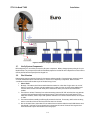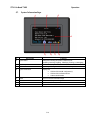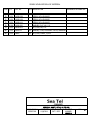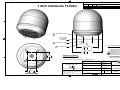
1
OPERATION AND INSTALLATION
FOR SEA TEL MODEL
ST24 SATELLITE TV RECEIVE-ONLY ANTENNA
Please record your Antenna Serial Number Here;
Antenna Model: _______Serial Number:
Sea Tel, Inc.
4030 Nelson Avenue
Concord, CA 94520
Tel: (925) 798-7979
Fax: (925) 798-7986
Web: : www.cobham.com\seatel
_______________
Sea Tel Europe
Unit 1, Orion Industrial Centre
Wide Lane, Swaythling
Southampton, UK S0 18 2HJ
Tel: 44 (0)23 80 671155
Fax: 44 (0)23 80 671166
Web: www.cobham.com\seatel
Sea Tel Inc is also doing business as Cobham Antenna Systems
September 26, 2011
Document. No. 132816 Revision C
Sea Tel Marine Stabilized Antenna systems are manufactured in the United
States of America.
Sea Tel is an ISO 9001:2008 registered company.
Certificate Number 13690 issued March 14, 2011.
The Coastal Series of Marine Stabilized Antenna Pedestals with Antenna Control Panel
complied with the requirements of European Norms and European Standards EN 60945
(1997) and prETS 300 339 (1998-03) on June 30, 1999. Sea Tel European Union Declaration
of Conformity for this equipment is contained in this manual.
Copyright Notice
All Rights Reserved. The information contained in this document is proprietary to Sea Tel, Inc.. This document
may not be reproduced or distributed in any form without prior consent of Sea Tel, Inc. The information in
this document is subject to change without notice. Copyright © 2010 Sea Tel, Inc is doing business as
Cobham SATCOM.
This document has been registered with the U.S. Copyright Office.
Revision History
REV
X
X1
ECO#
Date
August 24, 2010
September 30, 2010
X2
November 3, 2010
A
B
C
December 20, 2010
January 23, 2011
May 19, 2011
8491
Description
Preliminary Release
Updated text and graphics per Product Manager Feedback, added
LNB replacement Procedure, added Manual to AutoPol Conversion
Procedure
Updated text and graphics to reflect current software build features.
Added Setup Wizard procedure
Production Release
Updated text and graphics to reflect current software build features.
Updated text, graphics and drawings to reflect current production
build.
ii
By
ECM
ECM
ECM
ECM
ECM
ECM
ST24 Ku-Band TVRO
1.
1.
2.
3.
4.
5.
6.
Table of Contents
Table of Contents
TABLE OF CONTENTS ............................................................................................................................................................................... 1-1
QUICK START ................................................................................................................................................................................................ 2-1
2.1. GENERAL PANEL OPERATION ....................................................................................................................................................................... 2-1
2.2. TARGET A SATELLITE ..................................................................................................................................................................................... 2-1
INSTALLATION ............................................................................................................................................................................................. 3-1
3.1. VERIFY SYSTEM COMPONENTS ................................................................................................................................................................... 3-3
3.2. SITE SELECTION ............................................................................................................................................................................................. 3-3
3.2.1. Prepare the Antenna Radome Mounting Location ..................................................................................................3-4
3.2.2. Prepare the Antenna Control Panel mounting location........................................................................................3-5
3.3. CABLE AND EQUIPMENT INSTALLATION ................................................................................................................................................... 3-5
3.3.1. Determine your Cables ...........................................................................................................................................................3-6
3.4. ADE TO BDE CABLES: .................................................................................................................................................................................. 3-7
3.5. BDE CABLES ................................................................................................................................................................................................... 3-7
3.5.1. ST24 US/DLA/AUSSAT: ............................................................................................................................................................3-7
3.5.2. ST24 DiSEqC:................................................................................................................................................................................3-7
3.5.3. ST24 Euro:......................................................................................................................................................................................3-7
3.6. ANTENNA/RADOME INSTALLATION ........................................................................................................................................................... 3-8
3.7. GRAPHIC ANTENNA CONTROL PANEL .....................................................................................................................................................3-10
SETUP .................................................................................................................................................................................................................. 4-1
4.1. SETUP WIZARD .............................................................................................................................................................................................. 4-1
OPERATION ..................................................................................................................................................................................................... 5-1
5.1. GRAPHIC ANTENNA CONTROL PANEL ........................................................................................................................................................ 5-1
5.2. GACP HOME PAGE ....................................................................................................................................................................................... 5-2
5.3. SATELLITES PAGE ........................................................................................................................................................................................... 5-3
5.3.1. Satellite Target Page 1 ............................................................................................................................................................5-4
5.3.2. Satellite Target Page 2 ............................................................................................................................................................5-5
5.3.3. Satellite Edit Page 1..................................................................................................................................................................5-6
5.3.4. Satellite Edit Page 2..................................................................................................................................................................5-7
5.3.1. Satellite Preset Edit Page.......................................................................................................................................................5-8
5.3.2. Satellite View Page 1 ................................................................................................................................................................5-9
5.3.3. Satellite View Page 2 .............................................................................................................................................................5-10
5.4. CURRENT SETTINGS PAGE 1 ......................................................................................................................................................................5-11
5.4.1. Current Settings Page 2 ......................................................................................................................................................5-12
5.5. ANTENNA PAGE ............................................................................................................................................................................................5-13
5.5.1. Antenna Advanced Options Page 1...............................................................................................................................5-14
5.5.2. Antenna Advanced Options Page 2...............................................................................................................................5-15
5.6. POSITION.......................................................................................................................................................................................................5-18
5.7. SYSTEM INFORMATION PAGE....................................................................................................................................................................5-19
MAINTENANCE ............................................................................................................................................................................................ 6-1
6.1. WARRANTY INFORMATION .......................................................................................................................................................................... 6-1
6.2. WHO TO CONTACT FOR REPAIRS ................................................................................................................................................................. 6-1
6.1. PREVENTIVE MAINTENANCE........................................................................................................................................................................ 6-1
6.2. TOUCH SCREEN CALIBRATION .................................................................................................................................................................... 6-2
Table of Contents
7.
8.
ST24 Ku-Band TVRO
6.3. FAULT ISOLATION/TROUBLE-SHOOTING ................................................................................................................................................... 6-4
6.4. REPLACING AN LNB ....................................................................................................................................................................................... 6-5
6.5. MANUAL POL TO AUTOPOL CONVERSION PROCEDURE.......................................................................................................................... 6-7
ST SERIES TECHNICAL SPECIFICATIONS ................................................................................................................................ 7-1
7.1. INSTALLED WEIGHT ....................................................................................................................................................................................... 7-1
7.2. RADOME ........................................................................................................................................................................................................... 7-1
7.3. ANTENNA ......................................................................................................................................................................................................... 7-1
7.4. INTERCHANGEABLE LNB OPTIONS ............................................................................................................................................................. 7-1
7.4.1. US Circular LNB .......................................................................................................................................................................... 7-1
7.4.2. DLA Circular LNB ....................................................................................................................................................................... 7-2
7.4.3. Aussat Linear LNB ..................................................................................................................................................................... 7-2
7.4.4. European Quad Universal Linear LNB ............................................................................................................................. 7-2
7.5. PEDESTAL CONTROL UNIT ............................................................................................................................................................................ 7-2
7.6. STABILIZED PEDESTAL ................................................................................................................................................................................... 7-3
7.6.1. DVB Compliant Tracking Receiver.................................................................................................................................... 7-4
7.7. BELOW DECKS INTERFACE ............................................................................................................................................................................ 7-4
7.8. POWER REQUIREMENTS ................................................................................................................................................................................ 7-5
7.9. ENVIRONMENTAL ........................................................................................................................................................................................... 7-5
DRAWINGS ...................................................................................................................................................................................................... 8-1
1-2
ST24 Ku-Band TVRO
2.
Quick Start
Quick Start
Operation of the ST24 Series antenna is accomplished via the Graphic Antenna Control Panel (GACP). Once properly
configured, the antenna will automatically search for and identify the last targeted satellite held in memory. Because of
programming requirements or changing of geographic locations, you may be required to change what satellite you wish to
track.. Read below for general panel operation instructions.
2.1.
General Panel Operation
The GACP is a Panel Mount touch screen controller and navigation through its main and sub menu’s is accomplished
by pressing the desired icon itself and not the descriptive text below the icon. When applicable, the Left and Right
arrows may be used to navigate between main menu pages. The HOME icon may be pressed to return to the HOME
Page from any given menu or sub menu display. The Panel will go into a locked mode after five minutes of inactivity.
The Panel will go into Sleep mode after being in a locked mode for five minutes. NOTE: The Antenna will still be fully
functional. Press anywhere on the screen to bring the panel out of sleep mode and access the “Panel Unlock” screen.
The graphic to the right depicts the proper way to navigate through the menus by pressing
the icon itself.
The graphic to the right depicts the incorrect way to navigate through the menus by
pressing on the displayed text.
Navigational icons that are in full color are considered valid selections such as the “BACK”
arrow shown to the right.
Navigational icons that are in black and white are considered invalid selections, such as the
“BACK” arrow shown to the right.
2.2.
Target a Satellite
Use the following flow chart to target a satellite.
Is desired preset
available on page?
From the Home Page
Press the
Press the
Satellites Icon Target Icon
No
Press the
Right Arrow
Icon
Normal
Operation
Yes
Press the
Satellite Preset
Name Icon
Yes
Is desired preset
available on page?
2-1
No
Satellite
Preset is not
defined, refer
to “Configuring
a Preset”.
Quick Start
ST24 Ku-Band TVRO
THIS PAGE INTENIONALLY LEFT BLANK
2-2
ST24 Ku-Band TVRO
3.
Installation
Installation
Installation of the ST24 Antenna system will be presented into two major sections, the Above Decks Equipment (ADE) and the
Below Decks Equipment (BDE). This installation must be performed by or under the direct supervision of an authorized Sea Tel
Dealer for the limited warranty policy to be valid and enforced. A proper Site Survey MUST be performed prior to the actual
antenna installation to help ensure the best possible operation of the system. Proper planning is the key to a good installation,
please read this entire chapter thoroughly before beginning the actual installation and measure it against your site survey and
make adjust any details that you may have been overlooked.
The three following Simplified Block Diagrams (figures 1-3) are for visual reference only. Always refer to the System Block
Diagram, located in the drawings section of this manual for Coax and Wire interconnections and/or troubleshooting purposes.
Figure 1 ST24 DiSEqC Simplified Block Diagram
3-1
Installation
ST24 Ku-Band TVRO
Figure 2 ST24 US/DLA/AUSSAT Simplified Block Diagram
3-2
ST24 Ku-Band TVRO
Installation
Figure 3 ST24 Euro Simplified Block Diagram
3.1.
Verify System Components
Before beginning it is critical that you inventory all system components. Refer to the appropriate packing list for your
Model antenna. Any discrepancies should be immediately reported to the Sea Tel service department so that a Service
Call may be filed and the required parts be shipped out.
3.2.
Site Selection
Determine the optimum mounting location for the antenna radome assembly. Choosing the best mounting location
on vessels where there are few choice locations to choose from, is frequently a compromise. Below are some
considerations that should be taken as part of the Site Survey process.
•
1.
2.
3.
4.
Above Decks
Blockage: The antenna should be mounted where the antenna has a clear line-of-sight view to as much of
the sky as is practical. Choosing a location where masts or other structures do not block the satellite signal
from the dish as the boat turns will directly affect the antenna’s ability to locate and track the desired
satellite.
The antenna is at least 5 feet away from other transmitting antennas (HF, VHF and radar) that may generate
signals that may interfere with the Coastal Series antenna. The further away the Coastal antenna is from
these other antennas, the less impact their operation will have on it as will our antenna have less of an impact
on them.
The antenna radome assembly should be rigidly mounted to the boat. If necessary, reinforce the mounting
area to assure that it does not flex due to the boat motion or vibration.
Bow or the Stern? Due to the violent G-forces exerted onto an antenna while the vessel’s BOW heaves versus
the relatively “cushioned” G-forces exerted onto an antenna at the stern of the vessel choosing the Stern
would be the ‘best’ option with all other factors being equal.
3-3
Installation
5.
ST24 Ku-Band TVRO
Mounting Height: The pedestal mounting height specification is not intended to be an absolute restriction on
pedestal placement. It is generically referred to in the section of the manual which describes the vessel
motions for which the stabilization accuracy is guaranteed. An exact mounting height limit is difficult to
quantify since all vessels respond differently to various wave patterns and no two sea-states produce the
same pattern of waves. We can, however, state a range of practical conditions and show the expected
pedestal response and limits for those conditions. Figure 2-2 shows the expected antenna performance in
relationship to vessel motion.
Pedestal Mounting Height vs Roll Period
@ 25 degrees of Roll amplitude
Mounting Height in Feet
250
Not
Recomended
Reduced System
Performance
200
Possible
Mechanical
Failure
150
Full System Performance
Reduced Stabilization Accuracy
2.0G
Full System Performance
Full Stabilization Accuracy
100
1.0G
0.5G
50
0
6
7
8
9
10
11
12
13
14
15
Roll Period in Seconds
6.
•
Figure 3-2 Antenna Mounting Height vs. Antenna Performance
Below Decks Equipment. Knowing where the BDE will be installed is useful so that you can determine the
shortest and most convenient cable path from the antenna to below decks.
Below Decks
The Graphic Antenna Control Panel should be mounted in a convenient location for the operation of the
antenna system. It should be near one of the satellite receiver/television locations so that the receivers’ TV
screen can be viewed while the antenna is being operated. The supplied antenna control cable is routed from
the radome to the control panel, so routing path and cable length are important considerations both in
choosing the location of the control panel and to determine what type of RF cable should be used. The
technical specifications section of this manual provides the Sea Tel recommended cable type(s) as defined by
the overall cable run (from radome to the furthest receiver on the network).
Satellite receiver(s) and television set(s) - Satellite receiver(s) and television set(s) should be mounted near
each other in convenient viewing locations. If enclosed in a cabinet or panel, assure that there is adequate
airflow to prevent the receiver(s) and active matrix switch from over-heating and provide forced airflow if
needed. At each receiver location, leave a sufficient length of cable (service loop) to remove the receiver in
order to access its rear panel without pulling connections off of the rear panel.
3.2.1.
1.
2.
Prepare the Antenna Radome Mounting Location
Lay the Installation Template (drawing 132903) on the mounting surface location that you have
chosen to mount the radome on.
Align the radome “bow” mark on the template to be parallel to the bow of the boat. By default the
orientation of the “Sea Tel” logo is oriented towards BOW. You may as you see fit, adjust the
position of the “Bow” marker on template to orient the LOGO where you want it. When you are
satisfied with the position, tape the template in place.
3-4
ST24 Ku-Band TVRO
3.
4.
3.2.2.
1.
2.
3.
4.
5.
6.
3.3.
Installation
Using the center punch and hammer, mark the locations of the four radome mounting holes and the
cable passage. Remove the template drawing.
The 29” radome assembly provides the means to install the antenna to its
mounting surface on either a 9” D.B.C (factory default) or 12” D.B.C. You are only
required to use one of these hole patterns, not both.
Drill the four radome mounting holes using the 7/16” drill bit and the cable passage hole using a 4.5”
hole saw.
Prepare the Antenna Control Panel mounting location
Lay the Installation Template (drawing 132230) on the mounting surface location that you have
chosen to mount the Graphic Antenna Control Panel in.
Adjust the position of the template to center the Antenna Control Panel cutout portion of the
drawing where you want it. When you are satisfied with the position tape the template in place.
Using the center punch and hammer, mark the locations of the four mounting holes and the four
corners of the cutout area. Remove the template drawing.
Mark the perimeter of the cutout area. Drill a hole inside the perimeter of the cutout area to enable
you to cut the area out with the saw (the 1” hole saw might be used for this).
Cut the area out.
Drill out the four GACP mounting holes.
Cable and Equipment Installation
Using the Matrix list below, determine the System Block Diagram (SBD) document number for your model antenna
system. This SBD will be utilized for component interconnection information.
System Model
ST24, Euro, AutoPol
ST24 US, AutoPol
System Block Diagram Document #
132766-1
ST24 DLA, AutoPol
132766-3
ST24 DiSEqC, AutoPol
132766-4
ST24 Aussat, AutoPol
132766-5
ST24, Euro, Manual Pol
132766-6
ST24 US, Manual Pol
132766-7
ST24 DLA, Manual Pol
132766-8
ST24 DiSEqC, Manual Pol
132766-9
ST24 Aussat, AutoPol
132766-10
132766-2
3-5
Installation
ST24 Ku-Band TVRO
3.3.1.
Determine your Cables
In addition to the required Coaxial cable that will interconnect the above decks equipment with the below decks
equipment, you will need to determine what cables are going to be used to interconnect satellite receivers to the
televisions and if installed the surround sound system. The below guide may be used to help determine which cable
type is best suited for your installation. You should refer to the manual of the CFE equipment for additional guidance.
Video Connection Reference
Audio Connection Reference:
OK: Composite Video (Non-HD Video Only)
OK: Stereo RCA (2 channel Analog)
Typically an RCA Jack, this type
of connection combines and
transmits chrominance and
luminance information on a
single cable.
These RCA Jack connections are a means of
passing analog line-level audio signals (split
into left and right channels) from the
satellite receiver to your television or audio
amplifier.
Good: RCA (Multi-Channel Analog)
Good: S-Video (Non HD Video Only)
S-video connections transmit
the chrominance (color) and
luminance (brightness) portions
of a video signal along different
paths, allowing them to be
processed separately.
These preamp-level analog inputs
features jacks for up to 8 channels:
left front, right front, center channel,
left surround, right surround, and
subwoofer. Because the subwoofer
channel carries a limited range of frequencies, it's the
".1" in 5.1. A 6.1 input features the same jacks as a 5.1
input, but adds a back surround jack. A 7.1 input adds
two back surround jacks.
Better: XLR (Hi Resolution Analog)
Better: Component (HD Video Only )
This 3-cable connection allows the
chrominance (color) and luminance
(brightness) portions of a video
signal to be processed separately
.S-Video works similarly, but
component video improves color
accuracy further by splitting the chrominance
signal into two portions.
XLR audio
connections are
used primarily
with highperformance audio gear. This 3 pin connector
dedicates one of these pins for ground which helps
reduce electronic noise throughout the cable. A clasp
built into the round XLR plug locks it tightly into the
socket, ensuring a secure connection even during full
ships motion.
Best: HDMI (Both HD Video and Digital Audio)
HDMI is a multi-pin connection used for passing standard- and high-definition
digital video signals, as well as up to 8 discrete digital audio channels, through a
single cable.
3-6
ST24 Ku-Band TVRO
3.4.
Installation
ADE to BDE Cables:
3.4.1.
Antenna M&C Coax
Route and label an Antenna M&C Coax from the radome mounting location through the vessel and down to
the GACP mounting location.
Adjust the cable routing so that about 12 inches (30.5cm) of cable extends beyond the radome mounting
surface and about 4 inches (10cm) of cable extending out of the antenna control panel mounting surface.
3.4.2.
Satellite IF Coaxes
If required, route and the IF Coax(es) from the radome mounting location through the vessel and down to
the active multi-switch mounting location.
Adjust the cable routing so that about 12 inches (30.5cm) of cable extends beyond the radome mounting
surface and about 6 inches (10cm) of cable extending out of the antenna control panel mounting surface.
ST24 Euro Systems require 4 ADE to BDE Coax cables in addition to the Antenna M&C Coax. (Horizontal
High Band IF is stacked onto the Antenna M&C Coax)
ST24 US/DLA Systems require 2 ADE to BDE Coax Cables in addition to the Antenna M&C Coax.
ST24 DiSEqC System require 1 ADE to BDE Coax Cable in addition to the Antenna M&C Coax.
3.5.
BDE Cables
3.5.1.
ST24 US/DLA/AUSSAT:
3.5.1.1.
Multiswitch to Receiver(s)
Route the receiver IF coaxes from the Multiswitch mounting location to each of the receivers on the
network. Leave about 4 inches (10cm) of coax extending out each mounting location.
3.5.1.2.
Receiver(s) to Television(s)
Route the appropriate Audio/Visual cables from each Television mounting location to each of the
receivers mounting locations.
3.5.2.
ST24 DiSEqC:
3.5.2.1.
Multiswitch to DiSEqC Switch(es)
Route the receiver IF coaxes from the Multiswitch mounting location to each of the DiSEqC switch
mounting locations of the network. Leave about 4 inches (10cm) of coax extending out each
mounting location.
3.5.2.2.
DiSEqC Switch(es) to Receiver(s)
Route the receiver IF coaxes from DiSEqC switch mounting locations to each of the Receiver
mounting locations on the network. Leave about 4 inches (10cm) of coax extending out each
mounting location.
3.5.2.3.
Master DiSEqC Switch to GACP
Route the RS-232 Serial Cable from Master DiSEqC switch mounting locations to the GACP
mounting location. Leave about 4 inches (10cm) of coax extending out each mounting location.
3.5.2.4.
Receiver(s) to Television(s)
Route the appropriate Audio/Visual cables from each Television mounting location to each of the
receivers mounting locations.
3.5.3.
ST24 Euro:
3.5.3.1.
Multiswitch to Receiver(s)
Route the receiver IF coaxes from the Multiswitch mounting location to each of the receivers on the
network. Leave about 4 inches (10cm) of coax extending out each mounting location.
3-7
Installation
ST24 Ku-Band TVRO
3.5.3.2.
DC Power Cable (All Models)
3.5.3.2.1.
Supply to GACP
Route the DC Power cable assembly from the Vessel Power Source to the GACP mounting
location.
3.5.3.2.2.
Supply to Optional Power Switch
Perform the following step only if installing the optional power switch.
Route the DC Power cable assembly from the Vessel Power Source to the Optional Power
Switch mounting location.
Continue routing the remaining wires from the Optional Power Switch mounting location
to the GACP mounting location.
3.6.
Antenna/Radome Installation
Connect and secure the Antenna M&C Coax to the
M&C connector (Black Heat Shrink) at the base of
the radome.
Referring to the System Block Diagram for color
code callouts, connect and secure the IF Coaxes
from below decks to the connector bracket at the
base of the radome.
Apply Loctite™ thread locker to the four M8
Mounting Studs. Using the provided L-Key, install
and secure the studs onto the deck mounting
adapters located at the base of the radome.
Carefully place radome onto mounting location, be
careful not to pinch coaxes in between radome
and mounting surface.
3-8
ST24 Ku-Band TVRO
Installation
From below the mounting surface, apply Loctite
thread locker to the four M8 mounting studs.
Install the fender washers and the M8 nut and
Torque to 15 N-m.
NOTE: Graphic to the right is shown with the radome
mounting pad (normally installed flush with mounting
adapter) removed for clarity.
Using a 3mm Allen Wrench, remove the hardware
that secures radome top to radome base.
Use caution as to not lose the mounting inserts.
Locate and disengage the Elevation Stowage lock.
Refer to the Maintenance section of this manual
for complete procedures to stow and un-stow your
antenna.
3-9
Installation
ST24 Ku-Band TVRO
Locate and disengage the Azimuth Stowage lock.
Refer to the Maintenance section of this manual
for complete procedures to stow and un-stow your
antenna.
Perform range of motion check on antenna.
Verify free range in Azimuth, Elevation and Polarization drive.
3.7.
Graphic Antenna Control Panel
Label, Connect, and Secure the Antenna M&C
Coax (from Above Decks) to the RF In port of
the GACP.
Connect and secure the DC Power Cable
Assembly or the optional DC Power Switch
Cable Assembly onto the “BATT” connector of
the GACP.
Carefully remove GACP front lid to provide access to the four mounting holes.
Use caution as to not damage or pull out the “COM 0” interface harness that interconnects the display
module PCB to the controller PCB.
3-10
ST24 Ku-Band TVRO
Installation
Carefully install the GACP into the mounting
location while placing the excess cables into
the void of the mounting location and secure
using 4 self tapping screws.
Reinstall the GACP front lid to the enclosure.
3-11
Installation
ST24 Ku-Band TVRO
THIS PAGE INTENIONALLY LEFT BLANK
3-12
ST24 Ku-Band TVRO
4.
Setup
Setup
As a part of initial commissioning of the ST24 you will be required to configure and optimize the system to the clients specific
needs. An easy to use Setup Wizard will aid in this configuration process. Use the below procedures and flowcharts as a guide
to accomplish these tasks.
4.1.
Setup Wizard
When the system is turned on for the first time, the user will be prompted to configure the ST24 Antenna System for
operation via an easy 6 step setup wizard. Otherwise, this setup wizard is accessible on page two of the Antenna’s
Advanced Options menu.
1.
When prompted press the right arrow to begin the setup Wizard.
2.
If desired, press in the middle of the screen to calibrate the touch screen panel. Press the right arrow to skip
this step.
3.
Select the receive polarization type of the satellite(s) you intend to track and press the right arrow to accept
and continue.
4-1
Setup
ST24 Ku-Band TVRO
4.
Select the Antenna’s Polarization type, choose Auto if your feed assembly is fitted with a drive motor
otherwise choose Manual.
5.
Select the satellite switching mode. Choose "Active" to enable DiSEqC based satellite switching or choose
Inactive for manual satellite switching mode. NOTE: DiSEqC switches and compatible EchoStar based
receivers are required in order to run in Active mode.
4-2
ST24 Ku-Band TVRO
Setup
6.
(Skip to the next step if you have selected “Inactive” in the previous screen) Select the amount of satellites
required as specified by your service provider.
7.
Press the Right Arrow to begin the Satellite Preset selection process. The chosen presets will be displayed on
the Satellite Target, Edit, and View menus. If you are operating a DiSEqC based system, you will need to
know how many satellites are required before continuing. Refer to your EchoStar Receiver owner’s manual
for detailed information on how to perform a check switch test.
8.
Using the Up and/or Down Arrows, cycle through the available list of preset satellites until your desired
satellite is displayed the press save to submit. Press the right arrow to move to the next preset.
4-3
Setup
ST24 Ku-Band TVRO
9.
Using the same procedure in step 7, select and save your desired satellite for presets 2-6. If no additional
satellite presets are required set to Unused.
10. Select a text line to enter/edit the installing dealer contact information.
11. Repeat as required to enter/edit lines 2-4.
12. Select the Screen Lock Timeout parameter to define in whole minutes when the panel will go into a Panel
Lock Mode.
4-4
ST24 Ku-Band TVRO
Setup
13. Select the Screen Blank Timeout parameter to define in whole minutes when the panel will go into Blank
Mode.
14. Select the Screen Brightness Control to adjust the screen brightness.
15. Select the Time Zone Selection parameter to define the vessels current GMT time zone offset.
4-5
Setup
ST24 Ku-Band TVRO
16. After all the Panel Settings Parameters have been defined press the Right Arrow.
17. Press the Right Arrow to confirm the completion of the Setup Wizard and save to memory.
4-6
ST24 Ku-Band TVRO
5.
Operation
Operation
This section provides you with information about the menu displays of the GACP. Operation of your antenna system is
accomplished through these screens.
5.1.
Graphic Antenna Control Panel
Figure 4 GACP
#
1.
2.
3.
4.
5.
Description
RF output Port
RF Input Port
Status LED
USB Port
RS232 Antenna M&C Port
6.
7.
8.
9.
Optional NMEA Interface Port
Battery Input Port
Fuse
System Status
10.
11.
12.
13.
Time Stamp
AGC Signal Strength
Page Navigation
Panel Lock
Function
Not used
Antenna M&C to/from Above Decks
ADE to BDE FSK communications status LED
Used to perform software updates to the ST24 GACP
RS232 Serial M&C Port, used to perform software updates to the
ST24 PCU, or as a communication port w/ a DiSEqC Switch
Future Use
10-30VDC Supply input port
4 amp system fuse
Rolling Text indicating current system status of: Initializing, Unwrap,
Searching, Targeting, Identifying or Tracking.
Time Stamp, based on the on-board GPS antenna
Current system signal level
System menu navigational icons
Press to “Lock” the GACP interface.
5-1
Operation
5.2.
ST24 Ku-Band TVRO
GACP Home Page
#
1.
Description
System Status
2.
3.
4.
5.
6.
Time Stamp
AGC
Satellites
System Information
Antenna
Function
Rolling text indicating the systems current status of:
Initializing, Searching, Targeting, Tracking, Identifying or Unwrapping.
Current time stamp, based on the antenna’s on–board GPS.
System Signal Strength in AGC counts with visual signal bar.
Press to access the “Satellites” Main Menu Page.
Press to access the “System Information” Main Menu Page.
Press to access the “Antenna” Main Menu Page 1.
7.
8.
Panel Settings
Panel Lock
Press to access the “Panel Settings” Main Menu Page.
Press to “Lock” the GACP interface.
5-2
ST24 Ku-Band TVRO
5.3.
Operation
Satellites Page
#
1.
Description
System Status
2.
3.
4.
5.
6.
7.
8.
9.
10.
11.
Time Stamp
AGC
Target
Edit
Current Settings
View
Home
Back
Forward
Panel Lock
Function
Rolling text indicating the systems current status of:
Initializing, Searching, Targeting, Tracking, Identifying or Unwrapping.
Current time stamp, based on the antennas on –board GPS.
System Signal Strength in AGC counts with visual signal bar.
Click to access the Satellite Presets Target Page.
Click to access the Satellite Presets Edit Page.
Click to access the Current Settings Page.
Click to access the Satellite Presets View Page.
Click to access the GACP Home Page.
Click to access the previous Page.
Non-Functional in this screen.
Press to “Lock” the GACP interface.
5-3
Operation
ST24 Ku-Band TVRO
5.3.1.
Satellite Target Page 1
#
1.
Description
System Status
2.
3.
4.
Time Stamp
AGC
Satellite Presets 1-4
5.
6.
7.
8.
Home
Back
Forward
Panel Lock
Function
Rolling text indicating the systems current status of:
Initializing, Searching, Targeting, Identifying, Tracking, or Unwrapping.
Current time stamp, based on the antenna’s on –board GPS.
System Signal Strength in AGC counts with visual signal bar.
Click Satellite Presets Icon to submit satellite parameters and target
satellite.
Click to access the GACP Home Page.
Click to access the previous Page.
Click to access the Satellite Target Page 2
Press to “Lock” the GACP interface.
5-4
ST24 Ku-Band TVRO
5.3.2.
Operation
Satellite Target Page 2
#
1.
Description
System Status
2.
3.
4.
Time Stamp
AGC
Satellite Presets 5-8
5.
6.
7.
8.
Home
Back
Forward
Panel Lock
Function
Rolling text indicating the systems current status of:
Initializing, Searching, Targeting, Identifying, Tracking, or Unwrapping.
Current time stamp, based on the antenna’s on –board GPS.
System Signal Strength in AGC counts with visual signal bar.
Click Satellite Presets Icon to submit satellite parameters and target
satellite.
Click to access the GACP Home Page.
Click to access the Satellite Presets Page 1.
Non-Functional in this screen.
Press to “Lock” the GACP interface.
5-5
Operation
ST24 Ku-Band TVRO
5.3.3.
Satellite Edit Page 1
#
1.
Description
System Status
2.
3.
4.
Time Stamp
AGC
Satellite Presets 1-4
5.
6.
7.
8.
Home
Back
Forward
Panel Lock
Function
Rolling text indicating the systems current status of:
Initializing, Searching, Targeting, Identifying, Tracking, or Unwrapping.
Current time stam, based on the antenna’s on –board GPS.
System Signal Strength in AGC counts with visual signal bar.
Click Satellite Presets Icon to access and edit the parameters associated
with that preset satellite.
Click to access the GACP Home Page.
Click to access the previous Page.
Click to access the Satellite Edit Page 2.
Press to “Lock” the GACP interface.
5-6
ST24 Ku-Band TVRO
5.3.4.
Operation
Satellite Edit Page 2
#
1.
Description
System Status
2.
3.
4.
Time Stamp
AGC
Satellite Presets 5-8
5.
6.
7.
8.
Home
Back
Forward
Panel Lock
Function
Rolling text indicating the systems current status of:
Initializing, Searching, Targeting, Tracking, or Unwrapping.
Current time stamp in UTC, based on the antenna’s on –board GPS.
System Signal Strength in AGC counts with visual signal bar.
Click Satellite Presets Icon to access and edit the parameters associated
with that preset satellite.
Click to access the GACP Home Page.
Click to access the Satellite Presets Page 1.
Non-Functional in this screen.
Press to “Lock” the GACP interface.
5-7
Operation
ST24 Ku-Band TVRO
5.3.1.
Satellite Preset Edit Page
#
1.
Description
System Status
2.
3.
4.
5.
6.
7.
8.
Time Stamp
AGC
Frequency
Baud Rate
FEC
NID
Threshold Offset
9
10
11
Home
Back
Panel Lock
Function
Rolling text indicating the systems current status of:
Initializing, Searching, Targeting, Tracking, or Unwrapping.
Current time stamp in UTC, based on the antenna’s on –board GPS.
System Signal Strength in AGC counts with visual signal bar.
Click to edit the tracking receivers tuning frequency in MHz
Click to edit the tracking receivers Baud Rate
Click to edit the tracking receivers Forward Error Correction Rate
Click to edit the tracking receivers Hexadecimal Network ID
Click to edit the Threshold offset for this satellite preset. **This
parameter is used to calculate the Threshold value**
Click to access the GACP Home Page.
Click to access the previous page.
Press to “Lock” the GACP interface.
5-8
ST24 Ku-Band TVRO
5.3.2.
Operation
Satellite View Page 1
#
1.
Description
System Status
2.
3.
4.
Time Stamp
AGC
Satellite Presets 1-4
5.
6.
7.
8.
Home
Back
Forward
Panel Lock
Function
Rolling text indicating the systems current status of:
Initializing, Searching, Targeting, Identifying, Tracking, or Unwrapping.
Current time stamp, based on the antenna’s on –board GPS.
System Signal Strength in AGC counts with visual signal bar.
Click Satellite Presets Icon to access and view the parameters associated
with that preset satellite.
Click to access the GACP Home Page.
Click to access the previous Page.
Click to access the Satellite Edit Page 2.
Press to “Lock” the GACP interface.
5-9
Operation
ST24 Ku-Band TVRO
5.3.3.
Satellite View Page 2
#
1.
Description
System Status
2.
3.
4.
Time Stamp
AGC
Satellite Presets 5-8
5.
6.
7.
8.
Home
Back
Forward
Panel Lock
Function
Rolling text indicating the systems current status of:
Initializing, Searching, Targeting, Identifying, Tracking, or Unwrapping.
Current time stamp, based on the antennas on –board GPS.
System Signal Strength in AGC counts with visual signal bar.
Click Satellite Presets Icon to access and view the parameters associated
with that preset satellite.
Click to access the GACP Home Page.
Click to access the Satellite Presets Page 1.
Non-Functional in this screen.
Press to “Lock” the GACP interface.
5-10
ST24 Ku-Band TVRO
5.4.
Operation
Current Settings Page 1
#
1.
Description
System Status
2.
3.
4.
5.
6.
7.
8.
9.
Time Stamp
AGC
Satellite Info
Tuning Parameters
Home
Back
Forward
Panel Lock
Function
Rolling text indicating the systems current status of:
Initializing, Searching, Targeting, Identifying, Tracking, or Unwrapping.
Current time stamp, based on the antenna’s on –board GPS.
System Signal Strength in AGC counts with visual signal bar.
Read only display of current satellite in memory.
Click to view current tracking receiver.
Click to access the GACP Home Page.
Click to access the previous Page.
Non-Functional in this screen.
Press to “Lock” the GACP interface.
5-11
Operation
ST24 Ku-Band TVRO
5.4.1.
Current Settings Page 2
#
1.
Description
System Status
2.
3.
4.
5.
6.
7.
8.
Time Stamp
AGC
Tuning Information
Home
Back
Forward
Panel Lock
Function
Rolling text indicating the systems current status of:
Initializing, Searching, Targeting, Identifying, Tracking, or Unwrapping.
Current time stamp, based on the antennas on –board GPS.
System Signal Strength in AGC counts with visual signal bar.
Read only display of current tracking receiver settings in memory.
Click to access the GACP Home Page.
Click to access the previous Page.
Non-Functional in this screen.
Press to “Lock” the GACP interface.
5-12
ST24 Ku-Band TVRO
5.5.
Operation
Antenna Page
#
1.
Description
System Status
2.
3.
4.
5.
6.
7.
8.
9.
Time Stamp
AGC
Advanced Options
Position
Home
Back
Forward
Panel Lock
Function
Rolling text indicating the systems current status of:
Initializing, Searching, Targeting, Identifying, Tracking, or Unwrapping.
Current time stamp, based on the antenna’s on –board GPS.
System Signal Strength in AGC counts with visual signal bar.
Click to access the Advanced Options Page.
Click to access the Manual GPS Entry Page.
Click to access the GACP Home Page.
Click to access the previous Page.
Non-Functional in this screen.
Click to “Lock” the GACP interface.
5-13
Operation
ST24 Ku-Band TVRO
5.5.1.
Antenna Advanced Options Page 1
#
1.
Description
System Status
2.
3.
4.
5.
6.
7.
8.
9.
10.
11
Time Stamp
AGC
GPS Status
Home
Manual Control
Back
System Test
Forward
Setup Wizard
Auto Threshold Offset
Function
Rolling text indicating the systems current status of:
Initializing, Searching, Targeting, Identifying, Tracking, or Unwrapping.
Current time stamp, based on the antennas on –board GPS.
System Signal Strength in AGC counts with visual signal bar.
Click to access the GPS Status Page.
Click to access the GACP Home Page.
Click to access the Manual Control Main Menu Page.
Click to access the previous page.
Click to access the System Test Main Menu Page.
Click to access the Advanced Settings Page 2.
Click to start the interactive setup wizard.
Click to “Lock” the GACP interface.
5-14
ST24 Ku-Band TVRO
5.5.2.
Operation
Antenna Advanced Options Page 2
#
1.
Description
System Status
2.
3.
4.
5.
6.
7.
Time Stamp
AGC
Factory Restore
Home
Back
Panel Lock
Function
Rolling text indicating the systems current status of:
Initializing, Searching, Targeting, Identifying, Tracking, or Unwrapping.
Current time stamp, based on the antennas on –board GPS.
System Signal Strength in AGC counts with visual signal bar.
Click to restore all system settings to factory default.
Click to access the GACP Home Page.
Click to access the previous page.
Press to “Lock” the GACP interface.
5-15
Operation
ST24 Ku-Band TVRO
5.5.2.1. Manual Control Page
#
1.
Description
System Status
2.
3.
4.
5.
6.
7.
8.
9
10
11
12
13
14
POL
Time Stamp
AGC
Search
Tracking
Rev
Azimuth, Elevation, Polang
Az
El
Home
Back
Forward
Panel Lock
Function
Rolling text indicating the systems current status of:
Initializing, Searching, Targeting, Identifying, Tracking, or Unwrapping.
Click to drive feed assembly (Polang) CW or CCW.
Current time stamp, based on the antennas on –board GPS.
System Signal Strength in AGC counts with visual signal bar.
Click to initiate a linear azimuth sweep search pattern.
Click to toggle tracking state.
Click to “reverse” drive direction of current search pattern
Azimuth, Elevation, and Polarization Readout
Click to drive antenna in azimuth one whole degree.
Click to drive antenna in elevation one whole degree.
Click to access the GACP Home Page.
Click to access the previous Page.
Non-Functional in this screen.
Press to “Lock” the GACP interface.
5-16
ST24 Ku-Band TVRO
Operation
5.5.2.2. System Test Page
#
1.
Description
System Status
2.
3.
4.
Time Stamp
AGC
Power On Self Test Results
5.
6.
7.
8.
9.
10.
In Service Test
Out of Service Test
Home
Back
Forward
Panel Lock
Function
Rolling text indicating the systems current status of:
Initializing, Searching, Targeting, Identifying, Tracking, or Unwrapping.
Current time stamp, based on the antennas on –board GPS.
System Signal Strength in AGC counts with visual signal bar.
Click to access the results of the test performed during initialization of
the PCU or GACP.
Click to perform an “In Service System Test” of the PCU or GACP.
Click to perform an “Out of Service System Test” of the PCU or GACP.
Click to access the GACP Home Page.
Click to access the previous Page.
Non-Functional in this screen.
Press to “Lock” the GACP interface.
5-17
Operation
5.6.
ST24 Ku-Band TVRO
Position
#
1.
Description
System Status
2.
3.
Time Stamp
AGC
Function
Rolling text indicating the systems current status of:
Initializing, Searching, Targeting, Tracking, or Unwrapping.
Current time stamp in UTC, based on the antenna’s on –board GPS.
System Signal Strength in AGC counts with visual signal bar.
4.
Built-In GPS status
Displays whether or not the internal GPS is functional and active:
•
5.
6.
7.
8.
Home
Back
Forward
Panel Lock
NOTE: A Non-Active GPS Status will allow manual entry of
vessel location. Press on EDIT to enter edit mode.
Click to access the GACP Home Page.
Click to access the previous Page.
Non-Functional in this screen.
Press to “Lock” the GACP interface.
5-18
ST24 Ku-Band TVRO
5.7.
System Information Page
#
1.
Description
System Status
2.
3.
4.
Time Stamp
AGC
System Information
5.
6.
7.
8.
Operation
Home
Back
Forward
Panel Lock
Function
Rolling text indicating the systems current status of:
Initializing, Searching, Targeting, Identifying, Tracking, or Unwrapping.
Current time stamp, based on the antennas on –board GPS.
System Signal Strength in AGC counts with visual signal bar.
Displays the:
•
GACP and PCU Model configuration(s)
•
GACP and PCU Software Versions
• Antenna Serial Number
Click to access the GACP Home Page.
Click to access the previous Page.
Non-Functional in this screen.
Press to “Lock” the GACP interface.
5-19
Operation
ST24 Ku-Band TVRO
THIS PAGE INTENIONALLY LEFT BLANK
5-20
ST24 Ku-Band TVRO
6.
Maintenance
Maintenance
6.1.
Warranty Information
Sea Tel Inc. supports its ST24 Series systems with a warranty program unsurpassed in the industry. These systems are
backed by a TWO YEAR full warranty on parts and a ONE YEAR warranty on labor.
What’s Covered by the Limited Warranty?
The Sea Tel ST24 Series Limited Warranty is applicable for parts and labor coverage to the complete antenna system,
including all above-decks equipment (radome, pedestal, antenna, motors, electronics, wiring, etc.) and the antenna
control panel. It does not include television sets, DBS/DTH receivers, multi-switches or other distribution equipment,
whether or not supplied by Sea Tel. Televisions, DBS/DTH receivers and accessories are covered by the applicable
warranties of the respective manufacturers.
Factory refurbished components used to replace systems parts under this warranty are covered by this same warranty
as the original equipment for the balance of the original warranty term, or six months from the date of replacement,
whichever occurs last. Original Installation of the Coastal Series system must be accomplished by or under the
supervision of an authorized Sea Tel dealer for the Sea Tel Limited Warranty to be valid and in force.
Please refer to the complete warranty information included with your system.
6.2.
Who to contact for repairs
Should technical assistance be required to repair your system, the first contact should be to the agent/dealer you
purchased the equipment from. Please record their contact information below for future reference. Repairs to your
Coastal Series system must be accomplished by or under the supervision of an authorized Sea Tel dealer for the Sea
Tel Limited Warranty to be valid and in force.
Agent/Dealer: _________________________________________
Address:
_________________________________________
_________________________________________
Phone: ______________________ Fax: ____________________
Sea Tel can recommend local dealers that can provide service in your local area that can be contacted for assistance.
You can contact us directly at either of the locations below;
Sea Tel, Inc.
4030 Nelson Avenue
Concord, CA 94520 USA
Tel:
925-798-7979
Fax:
925-798-7986
Toll Free: 1-888-798-7979
Email: [email protected]
http://www.cobham.com/seatel
6.1.
Sea Tel Europe
Unit 1 Orion Industrial Centre
Wide Lane Swaythling
Southampton, UK S018 2HJ
Tel: +44 (0)23 80 671155
Fax: +44 (0)23 80 671166
e-mail: [email protected]
Preventive Maintenance
As needed - Clean the outside surface of the radome with warm soapy water to remove dust, grime and salt residue.
There is no other preventive maintenance required.
6-1
Maintenance
6.2.
ST24 Ku-Band TVRO
Touch Screen Calibration
If the icons on the GACP are non-responsive, it may require you to re-calibrate the touch screen itself. Use the
following procedure.
Install a straight 9 wire serial cable from the GACP’s
M&C port to an available com port on a
computer/laptop with Sea Tel Program Terminal
(ProgTerm) Installed.
If not already, apply power to the GACP.
Open up ProgTerm and select Coastal PCU to Panel
Translation mode.
In the main ProgTerm window, type in “&TC
<ENTER>”
That’s a dollar sign ($) capital T (T), capital C (C)
carriage return.
Follow the on-screen instructions to calibrate screen.
Press the circle located in the bottom left corner of
screen.
Press the circle located in the upper left corner of
screen.
Press the circle located in the top right corner of
screen.
6-2
ST24 Ku-Band TVRO
Maintenance
Press the circle located in the bottom right corner
of screen.
Press on an area of the screen near circled number
one and then continue to drag your finger towards
the middle of the circle.
Repeat for process for circles 2 -4.
Verify display provides positive feedback that the
new calibration has been saved.
Once complete it is MANDATORY that you cycle
DC power to the GACP.
This completes the Screen Calibration Procedure
and you may resume normal operation.
If GACP Icons are still non-responsive contact your
dealer.
6-3
Maintenance
6.3.
ST24 Ku-Band TVRO
Fault Isolation/Trouble-shooting
The following table is provided to help isolate problems in the ST24 Series Antenna systems.
Symptom
Possible Fault
GACP icons are non responsive
Touch screen requires calibration. Refer to the “Touch Screen
Calibration” procedure in the maintenance section of this manual.
Incorrect satellite. Press the desired preset to search for the correct
satellite.
Receiver fault. Refer to receiver manual for operation and testing.
May be in weak area of footprint
Receiver may not be generating correct voltage or tone output. Refer
to receiver manual for operation and testing.
Matrix switch may not be passing voltage or tone output from the
receiver. Contact your dealer/agent.
LNB assembly failure. Contact your dealer/agent.
Check for blockage
May be in weak area of footprint
Receiver may not be generating correct voltage or tone output. Refer
to receiver manual for operation and testing.
Is matrix switch buzzing or clicking. Contact your dealer/agent.
Check all coax cables for poor connection
Possible receiver failure. Contact your dealer/agent.
Possible antenna failure. Contact your dealer/agent.
Check +12 VDC input to GACP.
Verify that all connections on the rear of the antenna control panel
are properly seated.
Check the 4A fuse in the rear panel of the antenna control panel
Call dealer/agent for further assistance
Assure that at least one receiver is ON
Check for blockage
Assure correct starting elevation
May be out of satellite footprint
Check all coax cables for poor connection
Call dealer/agent for further assistance
Cycle antenna power OFF/ON to reinitialize the antenna.
Call dealer/agent for further assistance
Call dealer/agent for further assistance
Antenna tracking but receiver not
providing desired programming
Antenna tracking, receiver only gets
some desired channels
Intermittent freeze-framing of picture
Antenna does not come on when the
ON Power is applied
Antenna doesn’t track any satellites
(constantly searching)
Antenna in constant UNWRAP
Antenna tracks well at the pier, but loses
the satellite when underway
Antenna does not stay on satellite at
pier, or underway
Check all coax cables for poor connection
Call dealer/agent for further assistance
6-4
ST24 Ku-Band TVRO
6.4.
Maintenance
Replacing an LNB
Follow the procedure below to install and align a replacement Ku-Band circular receive LNB.
Unless otherwise noted, apply adhesive to all hardware per Sea Tel Specification Document 121730
Turn the DC supply power Off to the GACP.
Remove radome top.
You may need to rotate the antenna to gain access
the back of the reflector.
Using a 7/16” Wrench, remove the Coax(es)
connected to the LNB.
6-5
Maintenance
ST24 Ku-Band TVRO
Using an Allen Wrench, loosen the three set screws
used to secure the LNB to mounting cuff.
Remove LNB and place aside.
Install replacement LNB into mounting collar as close
to the orientation prior to removal and then tighten
down the set screws loosened earlier.
Reconnect and secure coax(es) removed earlier.
6-6
ST24 Ku-Band TVRO
6.5.
Maintenance
Manual Pol to AutoPol Conversion Procedure
Follow the procedure below to retrofit an existing ST24 with a Ku-Band Manual Polarization Feed assembly to an Auto
Polarization feed assembly. Please read through this entire procedure and verify the contents of conversion kit part
number 133235 prior to performing retrofit.
Unless otherwise noted, apply adhesive to all hardware per Sea Tel Specification Document 121730
Turn the DC supply power Off to the GACP.
Remove radome top.
You may need to rotate the antenna to gain access
the back of the reflector.
Using a 7/16” Wrench, remove the Coax(es)
connected to the LNB.
*Your installed LNB may vary from the graphic
depicted to the right*
6-7
Maintenance
ST24 Ku-Band TVRO
Using a 2.5mm Allen head wrench, remove the
hardware securing feed tube to reflector/feed
assembly. Carefully remove Feed tube and set aside
for future use.
Using a 4mm Allen Head Wrench, remove the
hardware securing the feed assembly to the
reflector.
On the Auto Polarization Feed Assembly to be
installed, manually rotate drive pulley (by hand) to
align the physical Polang stop in its’ center of range
as shown to the right.
6-8
ST24 Ku-Band TVRO
Maintenance
Carefully install Auto Polarization assembly into rear
of reflector as shown to the right.
Apply Loctite thread locker to the hardware provided
in kit, and using an 8mm driver secure feed assembly
to reflector.
6-9
Maintenance
ST24 Ku-Band TVRO
Install feed tube with the alignment notch in the
vertical axis as shown to the right. Secure using a
2.5mm Allen Wrench. DO NOT OVERTIGHTEN
Front view of the reflector showing a secured feed
tube.
CAUTION: DO NOT ATTEMPT TO ROTATE
THE ANTENNA IN AZIMUTH, ELEVATION, OR
POLARIZATION BY USING VERTEX
FEEDTUBE.
Using a #1 Phillips head screw driver, remove the
four screws that secure the PCU Cover to the
Antenna chassis and place aside for future use.
6-10
ST24 Ku-Band TVRO
Maintenance
Using snips carefully cut the tie wrap that secures
the (previously unused) IF coaxes to the GPS
Antenna Cable service loop.
Route the four coaxes up to and secure to LNB.
Using a tie wrap secure coaxes and Motor/Encoder
Harness to the LNB.
Using another tie wrap secure the coaxes to the
Motor/Encoder wire harness.
Ensure a large enough service loop to allow for full
range of motion in Polarization at all elevation look
angles.
Install the Motor Driver and Encoder IDC Connectors
on to the PCU PCB as shown to the right.
6-11
Maintenance
ST24 Ku-Band TVRO
Using caution as to not pinch, kink or otherwise
damage the IF coaxes and/or interface harnesses, reinstall and secure the PCU PCB cover.
Remove the counter balance weight(s) located in the
bottom side of right EL Pan.
Store weights for future use.
6-12
ST24 Ku-Band TVRO
7.
ST Series Technical Specifications
ST Series Technical Specifications
7.1.
Installed Weight
Total Weight (dry):
7.2.
Radome
Diameter
Height
Mounting
Wind:
Ingress Protection Rating
7.3.
ST24
29.13 inches (73.99 centimeters)
29.81 inches (75.72 centimeters)
4 x M8 fasteners equally spaced on 12.73” D.B.C. (9” pattern)
or
4 x M8 fasteners equally spaced on 16.97” D.B.C. (12” pattern)
Withstand relative average winds up to 125MPH from any direction.
All Sea Tel radomes have an IP rating of 56
Antenna
ST24
Spun Aluminum reflector
24 inch (61.0cm)
Backfire
Motorized Auto skew adjustment (ST24E and ST24AUS systems only)
Manual (ST24DBS,DLA,DiSEqC systems only)
45 dB
See Interchangeable Linear or Circular LNB information below.
Type
Size
Feed
Polarization
Min EIRP
LNB
7.4.
ST24
58 lbs. (26.3 kg)
Interchangeable LNB Options
The ST Series antennas can be easily fitted with a variety of LNB assemblies. Below are the LNBs which are currently
available for these systems.
7.4.1.
US Circular LNB
Sea Tel Part Number:
Type:
RF Frequencies:
IF Frequency:
LO Frequency:
Polarization modes:
Polarization control:
127444-1
Dual output
12.2 - 12.7 GHz
950 - 1450 MHz
11.250 GHz
LHCP or RHCP circular
18VDC (LHCP) or 13VDC (RHCP) voltage switched
7-1
ST Series Technical Specifications
7.4.2.
DLA Circular LNB
Sea Tel Part Number:
Type:
RF Frequencies:
IF Frequency:
LO Frequency:
Polarization modes:
Polarization control:
7.4.3.
131942-1
Dual output
11.7 - 12.75 GHz
1000 - 2050 MHz
10.7 GHz
Horizontal or Vertical Linear
18VDC (H) or 13VDC (V) voltage switched
European Quad Universal Linear LNB
Sea Tel Part Number:
Type:
RF Frequencies:
IF Frequencies:
LO Frequencies:
Polarization modes:
Band Selection:
7.5.
115075-2
Dual output
11.45 - 12.2 GHz
950 - 1700 MHz
10.5 GHz
LHCP or RHCP circular
18VDC (LHCP) or 13VDC (RHCP) voltage switched
Aussat Linear LNB
Sea Tel Part Number:
Type:
RF Frequencies:
IF Frequency:
LO Frequency:
Polarization modes:
Polarization control:
7.4.4.
ST24 Ku-Band TVRO
132463
Quad output
Low Band High Band
10.7 - 11.7 GHz
11.7 - 12.75 GHz
950 - 1950 MHz
1100 - 2150 MHz
9.75 GHz
10.6 GHz
2 Horiz., 2 Vert. Outputs
2 Hi, 2 Lo band outputs
Pedestal Control Unit
Size
Features
Connectors
Below Decks Interface
Motors
Encoders
RF Signal Monitor
RF Signal Output
GPS Signal Monitor
Service Port
2 in x 8 in x 5 in (5.08 cm x 20.32 cm x 12.70 cm)
Fully integrated controller, sensors, motor drivers, RF Signal Monitor
and Output, GPS signal monitor(s), and BDE communications.
Type F
IDC
IDC
Type F
Type F
RJ45
Mini B USB
7-2
ST24 Ku-Band TVRO
7.6.
ST Series Technical Specifications
Stabilized Pedestal
Type
Stabilization
Stab Accuracy
Motors
Elevation
Azimuth
Pol skew Motor
Inertial Reference
Gravity Reference
Azimuth Reference
Stabilization rates
Roll/Pitch
AZ./Turn
Range of Motion
Elevation
Azimuth
Polarization
Maximum Ship Motion
Roll
Pitch
Elevation Pointing
+/- 0 degrees of Roll
Ship Motions for specified pointing accuracy
Roll
Pitch
Yaw
Turning rate
Two-axis positioning (Elevation & Azimuth) and Polarization
3 Dimensional Velocity mode Servo
1.5 degrees MAX, 0.7 degrees RMS in presence of specified ship
motions for pointing accuracy (see below).
Size 23 DC Step Motors with PWM Microstep drive
Size 23 High Torque w/ Encoder
Size 23 High Torque
Size 17 High Torque w/ Encoder
3 single axis Solid State Silicon Rate Sensors
Dual Axis MEMS accelerometer
Closed Loop Tracking on Satellite signal
> 25 degrees / second
> 15 degrees / second
-10 to 80 degrees
680 degrees
+/- 120 degrees (240˚ Total)
+/- 25 degrees (implied)
+/- 15 degrees (implied)
+5 to +65 degrees
+/-20 degrees with 8-12 sec periods
+/-10 degrees with 6-12 sec periods
+/-8 degrees with 15 to 20 sec periods
Up to 12 deg/sec.
7-3
ST Series Technical Specifications
7.6.1.
DVB Compliant Tracking Receiver
Internal Satellite Identification Receiver
Tuning range
Input RF Level
Output RF Level
Sensitivity
Bandwidth
Polarity switching
Band Switching:
Satellite ID
QPSK Demodulator
FEC Decoder
Pipeline Decoder
7.7.
ST24 Ku-Band TVRO
950 to 2150 MHz in 1 MHz increments in DVB Mode.
-85 to -25 dBm typical
Input level +/- 1 dB typical
30 mV / dB typical
Selectable in DVB Mode,
7.5MHz with a Baud Rate =/< 5k
20 MHz with a Baud Rate >5k)
13 VDC output to select Vertical or RHCP polarity.
18 VDC to output select Horizontal or LHCP polarity
22kHz continuous tone output to select High band, No tone to
select Low band.
Network ID for DVB signals. QPSK demodulator and FEC decoder
lock for DSS, or DVB without NID (forced NID).
3000 to 30000 baud (ksps)
1/2, 2/3, 3/4, 5/6, 6/7, 7/8, or Automatic.
DVB or DSS compatible.
Below Decks Interface
Size
Front Panel
Mounted Enclosure
Display Viewing Area
6.25 in x 4.65 in (15.88 cm x 11.81 cm)
6.007 in x 4.437 in x 3.2 in (15.26 cm x 11.27 cm x 8.13 cm)
2.1220 in 3.7402 in 53.9 mm 95.0 mm)
Display
Type
Resolution
Horizontal Viewing Angle
Vertical Viewing Angle
Backlight Display Type
Indicators
Service Ports
Serial Interface
USB Interface
NMEA Interface
Connectors
DC Power
Pedestal Interface
IF
RS-232 Interface
4.3 in (10.92 cm) TFT
480 x 272 WQVGA
130 deg typical
60 deg (Top) 50 deg (Bottom) typical
LED
1 LED status indicators
9600 baud RS-232 Interface for diagnostics and computer interface.
Mini B USB Interface (Future Use)
NMEA 0183 Interface (Future Use)
2 Screw Terminals
Type F (for FSK Communications)
Type F (950 to 2150Mhz Typical_)
9 Pin Male D-Sub connector (DTE)
7-4
ST24 Ku-Band TVRO
7.8.
Power Requirements
Voltage
Current
Transient Protection
Load Dump
Inductive coupling
Reverse Battery
24V Jump Start
7.9.
ST Series Technical Specifications
10-30 VDC normal operating range
3.0 Amps nominal @ 13.8 VDC
60 Volts
+/- 200V @1µSecond
Indefinite
Indefinite
Environmental
Temperature
Humidity
Rain
Wind
Corrosion
Storage Temperature
-20 to +55 degrees C.
Up to l00% @ 40 degrees C.
Up to 4 inches per hour. Degraded RF performance when the
radome surface is wet.
Up to 125 MPH from any direction.
Parts are corrosion resistant or treated to endure effects of salt air
and salt spray.
-40 to +70 degrees C
7-5
ST Series Technical Specifications
ST24 Ku-Band TVRO
THIS PAGE INTENTIONALLY LEFT BLANK
7-6
ST24 Ku-Band TVRO
8.
Drawings
DRAWINGS
The following drawings have been provided as a reference tool. Should you have any questions or concerns please notify the
Sea Tel Service Department.
Drawing
132500
132370
132766
132765
132903
132230-1
133491
Title
System, ST24,
General Assembly, ST24,
System Block Diagram, ST24,
Antenna System Schematic, ST24
Installation Template, 29 inch radome
Installation Template, GACP
Installation Arrangement ST24
8-1
8-3
8-6
8-9
8-12
8-13
8-14
8-15
Drawings
ST24 Ku-Band TVRO
THIS PAGE INTENTIONALLY LEFT BLANK
8-2
SINGLE LEVEL MFG BILL OF MATERIAL
FIND QTY
PART NO
REV DESCRIPTION
REFERENCE DESIGNATOR
1
1 EA 132370-1
C
GENERAL ASS'Y, ST24, AUTO POL
PL C1 AntSys_Crate
2
1 EA 132542-1
A
RADOME ASS'Y, GA INSTALL, 29 IN, ST24
PL C1 AntSys_Crate
3
1 EA 132463-1
C
LNBF, QUAD, KU, INVERTO, MODIFIED
PL C1 I1 SN w/132370-1,1
AntSys_Crate
4
1 EA 130922-1
A1 ENCLOSURE ASS'Y, GACP
(NOT SHOWN)
4
1 EA 130922-1
A1 ENCLOSURE ASS'Y, GACP
PL C1 SN AntSys_Crate
5
1 EA 122583-6
B
CABLE ASS'Y, RG-6, F(M) TO F(M), 6FT
(NOT SHOWN)
5
1 EA 122583-6
B
CABLE ASS'Y, RG-6, F(M) TO F(M), 6FT
PL C1 AntSys_Crate
6
1 EA 132877
A
HARNESS ASS'Y, DC POWER GACP
(NOT SHOWN)
6
1 EA 132877
A
HARNESS ASS'Y, DC POWER GACP
PL C1 AntSys_Crate
10
1 EA 133197
A
CUSTOMER DOC PACKET, ST24
PL C1 AntSys_Crate
10
1 EA 133197
A
CUSTOMER DOC PACKET, ST24
(NOT SHOWN)
15
1 EA 133666-1
A
BRACKET, POLANG HARNESS
20
1 EA 111679-5
B
CABLE CLAMP, NYLON, .375 DIA, #8 MTG
21
2 EA 119801-019
B
CABLE TIE, NYLON, 7.5 IN, NATURAL
50
2 EA 119973-107
SCREW. SOCKET HD, M4 X 6, S.S.
58
3 EA 114580-230
WASHER, FLAT, M4, S.S.
59
1 EA 120089-231
NUT, HEX, M4, S.S.
(NOT SHOWN)
SYSTEM, ST24, EURO, AUTO POL
PROD FAMILY
SERIES 98E
EFF. DATE
10/6/2011
SHT 1 OF 2
DRAWING
NUMBER
132500-001
REV
A
SINGLE LEVEL MFG BILL OF MATERIAL
FIND QTY
PART NO
REV DESCRIPTION
REFERENCE DESIGNATOR
1
1 EA 132370-1
C
GENERAL ASS'Y, ST24, AUTO POL
PL C1 AntSys_Crate
2
1 EA 132542-1
A
RADOME ASS'Y, GA INSTALL, 29 IN, ST24
PL C1 AntSys_Crate
3
1 EA 127444-1
A
LNBF MOD, DUAL DBS, CAL AMP
PL C1 I1 SN w/132370-1,1
AntSys_Crate
4
1 EA 130922-1
A1 ENCLOSURE ASS'Y, GACP
(NOT SHOWN)
4
1 EA 130922-1
A1 ENCLOSURE ASS'Y, GACP
PL C1 SN AntSys_Crate
5
1 EA 122583-6
B
CABLE ASS'Y, RG-6, F(M) TO F(M), 6FT
(NOT SHOWN)
5
1 EA 122583-6
B
CABLE ASS'Y, RG-6, F(M) TO F(M), 6FT
PL C1 AntSys_Crate
6
1 EA 132877
A
HARNESS ASS'Y, DC POWER GACP
(NOT SHOWN)
6
1 EA 132877
A
HARNESS ASS'Y, DC POWER GACP
PL C1 AntSys_Crate
10
1 EA 133197
A
CUSTOMER DOC PACKET, ST24
PL C1 AntSys_Crate
10
1 EA 133197
A
CUSTOMER DOC PACKET, ST24
(NOT SHOWN)
15
1 EA 133666-1
A
BRACKET, POLANG HARNESS
20
1 EA 111679-5
B
CABLE CLAMP, NYLON, .375 DIA, #8 MTG
21
2 EA 119801-019
B
CABLE TIE, NYLON, 7.5 IN, NATURAL
50
2 EA 119973-107
SCREW. SOCKET HD, M4 X 6, S.S.
58
3 EA 114580-230
WASHER, FLAT, M4, S.S.
59
1 EA 120089-231
NUT, HEX, M4, S.S.
(NOT SHOWN)
SYSTEM, ST24, US, AUTO POL
PROD FAMILY
SERIES 98E
EFF. DATE
10/6/2011
SHT 1 OF 2
DRAWING
NUMBER
132500-002
REV
A
SINGLE LEVEL MFG BILL OF MATERIAL
FIND QTY
PART NO
REV DESCRIPTION
REFERENCE DESIGNATOR
1
1 EA 132370-1
C
GENERAL ASS'Y, ST24, AUTO POL
PL C1 AntSys_Crate
2
1 EA 132542-1
A
RADOME ASS'Y, GA INSTALL, 29 IN, ST24
PL C1 AntSys_Crate
3
1 EA 115075-2
G2 LNB MOD, DUAL DLA
PL C1 I1 SN w/132370-1,1
AntSys_Crate
4
1 EA 130922-1
A1 ENCLOSURE ASS'Y, GACP
(NOT SHOWN)
4
1 EA 130922-1
A1 ENCLOSURE ASS'Y, GACP
PL C1 SN AntSys_Crate
5
1 EA 122583-6
B
CABLE ASS'Y, RG-6, F(M) TO F(M), 6FT
(NOT SHOWN)
5
1 EA 122583-6
B
CABLE ASS'Y, RG-6, F(M) TO F(M), 6FT
PL C1 AntSys_Crate
6
1 EA 132877
A
HARNESS ASS'Y, DC POWER GACP
(NOT SHOWN)
6
1 EA 132877
A
HARNESS ASS'Y, DC POWER GACP
PL C1 AntSys_Crate
10
1 EA 133197
A
CUSTOMER DOC PACKET, ST24
(NOT SHOWN)
10
1 EA 133197
A
CUSTOMER DOC PACKET, ST24
PL C1 AntSys_Crate
15
1 EA 133666-1
A
BRACKET, POLANG HARNESS
20
1 EA 111679-5
B
CABLE CLAMP, NYLON, .375 DIA, #8 MTG
21
2 EA 119801-019
B
CABLE TIE, NYLON, 7.5 IN, NATURAL
50
2 EA 119973-107
SCREW. SOCKET HD, M4 X 6, S.S.
58
3 EA 114580-230
WASHER, FLAT, M4, S.S.
59
1 EA 120089-231
NUT, HEX, M4, S.S.
(NOT SHOWN)
SYSTEM, ST24, DLA, AUTO POL
PROD FAMILY
SERIES 98E
EFF. DATE
10/6/2011
SHT 1 OF 2
DRAWING
NUMBER
132500-003
REV
A
SINGLE LEVEL MFG BILL OF MATERIAL
FIND QTY
PART NO
REV DESCRIPTION
REFERENCE DESIGNATOR
1
1 EA 132370-1
C
GENERAL ASS'Y, ST24, AUTO POL
PL C1 AntSys_Crate
2
1 EA 132542-1
A
RADOME ASS'Y, GA INSTALL, 29 IN, ST24
PL C1 AntSys_Crate
3
1 EA 130210
A1 LNB, DISHPRO, SINGLE, MODIFIED
PL C1 I1 SN w/132370-1,1
AntSys_Crate
4
1 EA 130922-1
A1 ENCLOSURE ASS'Y, GACP
(NOT SHOWN)
4
1 EA 130922-1
A1 ENCLOSURE ASS'Y, GACP
PL C1 SN AntSys_Crate
5
1 EA 122583-6
B
CABLE ASS'Y, RG-6, F(M) TO F(M), 6FT
(NOT SHOWN)
5
1 EA 122583-6
B
CABLE ASS'Y, RG-6, F(M) TO F(M), 6FT
PL C1 AntSys_Crate
6
1 EA 132877
A
HARNESS ASS'Y, DC POWER GACP
(NOT SHOWN)
6
1 EA 132877
A
HARNESS ASS'Y, DC POWER GACP
PL C1 AntSys_Crate
7
1 EA 129734
E
ENCLOSURE ASSY, DISEQC VOLTAGE
SWITCH
(NOT SHOWN)
7
1 EA 129734
E
ENCLOSURE ASSY, DISEQC VOLTAGE
SWITCH
PL C1 AntSys_Crate
8
1 EA 120643-25
B
CABLE ASS'Y, RS232, 9-WIRE, STRAIGHT,
PL C1 AntSys_Crate
8
1 EA 120643-25
B
CABLE ASS'Y, RS232, 9-WIRE, STRAIGHT,
(NOT SHOWN)
10
1 EA 133197
A
CUSTOMER DOC PACKET, ST24
PL C1 AntSys_Crate
10
1 EA 133197
A
CUSTOMER DOC PACKET, ST24
(NOT SHOWN)
15
1 EA 133666-1
A
BRACKET, POLANG HARNESS
20
1 EA 111679-5
B
CABLE CLAMP, NYLON, .375 DIA, #8 MTG
21
2 EA 119801-019
B
CABLE TIE, NYLON, 7.5 IN, NATURAL
50
2 EA 119973-107
SCREW. SOCKET HD, M4 X 6, S.S.
58
3 EA 114580-230
WASHER, FLAT, M4, S.S.
59
1 EA 120089-231
NUT, HEX, M4, S.S.
SYSTEM, ST24, DISEQC, AUTO POL
PROD FAMILY
SERIES 98E
EFF. DATE
10/6/2011
SHT 1 OF 2
DRAWING
NUMBER
132500-004
REV
A
SINGLE LEVEL MFG BILL OF MATERIAL
FIND QTY
PART NO
REV DESCRIPTION
REFERENCE DESIGNATOR
1
1 EA 132370-1
C
GENERAL ASS'Y, ST24, AUTO POL
PL C1 AntSys_Crate
2
1 EA 132542-1
A
RADOME ASS'Y, GA INSTALL, 29 IN, ST24
PL C1 AntSys_Crate
3
1 EA 131492-1
A
LNB, KU-BAND ACER LNBFTUP, MODIFIED
PL C1 I1 SN w/132370-1,1
AntSys_Crate
4
1 EA 130922-1
A1 ENCLOSURE ASS'Y, GACP
(NOT SHOWN)
4
1 EA 130922-1
A1 ENCLOSURE ASS'Y, GACP
PL C1 SN AntSys_Crate
5
1 EA 122583-6
B
CABLE ASS'Y, RG-6, F(M) TO F(M), 6FT
(NOT SHOWN)
5
1 EA 122583-6
B
CABLE ASS'Y, RG-6, F(M) TO F(M), 6FT
PL C1 AntSys_Crate
6
1 EA 132877
A
HARNESS ASS'Y, DC POWER GACP
(NOT SHOWN)
6
1 EA 132877
A
HARNESS ASS'Y, DC POWER GACP
PL C1 AntSys_Crate
10
1 EA 133197
A
CUSTOMER DOC PACKET, ST24
PL C1 AntSys_Crate
10
1 EA 133197
A
CUSTOMER DOC PACKET, ST24
(NOT SHOWN)
15
1 EA 133666-1
A
BRACKET, POLANG HARNESS
20
1 EA 111679-5
B
CABLE CLAMP, NYLON, .375 DIA, #8 MTG
21
2 EA 119801-019
B
CABLE TIE, NYLON, 7.5 IN, NATURAL
50
2 EA 119973-107
SCREW. SOCKET HD, M4 X 6, S.S.
58
3 EA 114580-230
WASHER, FLAT, M4, S.S.
59
1 EA 120089-231
NUT, HEX, M4, S.S.
(NOT SHOWN)
SYSTEM, ST24, AUSSAT, AUTO POL
PROD FAMILY
SERIES 98E
EFF. DATE
10/6/2011
SHT 1 OF 2
DRAWING
NUMBER
132500-005
REV
A
SINGLE LEVEL MFG BILL OF MATERIAL
FIND QTY
PART NO
REV DESCRIPTION
REFERENCE DESIGNATOR
1
1 EA 132370-2
C
GENERAL ASS'Y, ST24, MANUAL POL
PL C1 AntSys_Crate
2
1 EA 132542-1
A
RADOME ASS'Y, GA INSTALL, 29 IN, ST24
PL C1 AntSys_Crate
3
1 EA 132463-1
C
LNBF, QUAD, KU, INVERTO, MODIFIED
PL C1 I1 SN w/132370-1,1
AntSys_Crate
4
1 EA 130922-1
A1 ENCLOSURE ASS'Y, GACP
(NOT SHOWN)
4
1 EA 130922-1
A1 ENCLOSURE ASS'Y, GACP
PL C1 SN AntSys_Crate
5
1 EA 122583-6
B
CABLE ASS'Y, RG-6, F(M) TO F(M), 6FT
(NOT SHOWN)
5
1 EA 122583-6
B
CABLE ASS'Y, RG-6, F(M) TO F(M), 6FT
PL C1 AntSys_Crate
6
1 EA 132877
A
HARNESS ASS'Y, DC POWER GACP
PL C1 AntSys_Crate
6
1 EA 132877
A
HARNESS ASS'Y, DC POWER GACP
(NOT SHOWN)
10
1 EA 133197
A
CUSTOMER DOC PACKET, ST24
(NOT SHOWN)
10
1 EA 133197
A
CUSTOMER DOC PACKET, ST24
PL C1 AntSys_Crate
SYSTEM, ST24, EURO, MANUAL POL
PROD FAMILY
SERIES 98E
EFF. DATE
10/6/2011
SHT 1 OF 1
DRAWING
NUMBER
132500-006
REV
A
SINGLE LEVEL MFG BILL OF MATERIAL
FIND QTY
PART NO
REV DESCRIPTION
REFERENCE DESIGNATOR
1
1 EA 132370-2
C
GENERAL ASS'Y, ST24, MANUAL POL
PL C1 AntSys_Crate
2
1 EA 132542-1
A
RADOME ASS'Y, GA INSTALL, 29 IN, ST24
PL C1 AntSys_Crate
3
1 EA 127444-1
A
LNBF MOD, DUAL DBS, CAL AMP
PL C1 I1 SN w/132370-1,1
AntSys_Crate
4
1 EA 130922-1
A1 ENCLOSURE ASS'Y, GACP
(NOT SHOWN)
4
1 EA 130922-1
A1 ENCLOSURE ASS'Y, GACP
PL C1 SN AntSys_Crate
5
1 EA 122583-6
B
CABLE ASS'Y, RG-6, F(M) TO F(M), 6FT
(NOT SHOWN)
5
1 EA 122583-6
B
CABLE ASS'Y, RG-6, F(M) TO F(M), 6FT
PL C1 AntSys_Crate
6
1 EA 132877
A
HARNESS ASS'Y, DC POWER GACP
PL C1 AntSys_Crate
6
1 EA 132877
A
HARNESS ASS'Y, DC POWER GACP
(NOT SHOWN)
10
1 EA 133197
A
CUSTOMER DOC PACKET, ST24
(NOT SHOWN)
10
1 EA 133197
A
CUSTOMER DOC PACKET, ST24
PL C1 AntSys_Crate
SYSTEM, ST24, US, MANUAL POL
PROD FAMILY
SERIES 98E
EFF. DATE
10/6/2011
SHT 1 OF 1
DRAWING
NUMBER
132500-007
REV
A
SINGLE LEVEL MFG BILL OF MATERIAL
FIND QTY
PART NO
REV DESCRIPTION
REFERENCE DESIGNATOR
1
1 EA 132370-2
C
GENERAL ASS'Y, ST24, MANUAL POL
PL C1 AntSys_Crate
2
1 EA 132542-1
A
RADOME ASS'Y, GA INSTALL, 29 IN, ST24
PL C1 AntSys_Crate
3
1 EA 115075-2
G2 LNB MOD, DUAL DLA
PL C1 I1 SN w/132370-1,1
AntSys_Crate
4
1 EA 130922-1
A1 ENCLOSURE ASS'Y, GACP
(NOT SHOWN)
4
1 EA 130922-1
A1 ENCLOSURE ASS'Y, GACP
PL C1 SN AntSys_Crate
5
1 EA 122583-6
B
CABLE ASS'Y, RG-6, F(M) TO F(M), 6FT
(NOT SHOWN)
5
1 EA 122583-6
B
CABLE ASS'Y, RG-6, F(M) TO F(M), 6FT
PL C1 AntSys_Crate
6
1 EA 132877
A
HARNESS ASS'Y, DC POWER GACP
PL C1 AntSys_Crate
6
1 EA 132877
A
HARNESS ASS'Y, DC POWER GACP
(NOT SHOWN)
10
1 EA 133197
A
CUSTOMER DOC PACKET, ST24
(NOT SHOWN)
10
1 EA 133197
A
CUSTOMER DOC PACKET, ST24
PL C1 AntSys_Crate
SYSTEM, ST24, DLA, MANUAL POL
PROD FAMILY
SERIES 98E
EFF. DATE
10/6/2011
SHT 1 OF 1
DRAWING
NUMBER
132500-008
REV
A
SINGLE LEVEL MFG BILL OF MATERIAL
FIND QTY
PART NO
REV DESCRIPTION
REFERENCE DESIGNATOR
1
1 EA 132370-2
C
GENERAL ASS'Y, ST24, MANUAL POL
PL C1 AntSys_Crate
2
1 EA 132542-1
A
RADOME ASS'Y, GA INSTALL, 29 IN, ST24
PL C1 AntSys_Crate
3
1 EA 130210
A1 LNB, DISHPRO, SINGLE, MODIFIED
PL C1 I1 SN w/132370-1,1
AntSys_Crate
4
1 EA 130922-1
A1 ENCLOSURE ASS'Y, GACP
(NOT SHOWN)
4
1 EA 130922-1
A1 ENCLOSURE ASS'Y, GACP
PL C1 SN AntSys_Crate
5
1 EA 122583-6
B
CABLE ASS'Y, RG-6, F(M) TO F(M), 6FT
(NOT SHOWN)
5
1 EA 122583-6
B
CABLE ASS'Y, RG-6, F(M) TO F(M), 6FT
PL C1 AntSys_Crate
6
1 EA 132877
A
HARNESS ASS'Y, DC POWER GACP
(NOT SHOWN)
6
1 EA 132877
A
HARNESS ASS'Y, DC POWER GACP
PL C1 AntSys_Crate
7
1 EA 129734
E
ENCLOSURE ASSY, DISEQC VOLTAGE
SWITCH
(NOT SHOWN)
7
1 EA 129734
E
ENCLOSURE ASSY, DISEQC VOLTAGE
SWITCH
PL C1 AntSys_Crate
8
1 EA 120643-25
B
CABLE ASS'Y, RS232, 9-WIRE, STRAIGHT,
PL C1 AntSys_Crate
8
1 EA 120643-25
B
CABLE ASS'Y, RS232, 9-WIRE, STRAIGHT,
(NOT SHOWN)
10
1 EA 133197
A
CUSTOMER DOC PACKET, ST24
PL C1 AntSys_Crate
10
1 EA 133197
A
CUSTOMER DOC PACKET, ST24
(NOT SHOWN)
SYSTEM, ST24, DISEQC, MANUAL POL
PROD FAMILY
SERIES 98E
EFF. DATE
10/6/2011
SHT 1 OF 2
DRAWING
NUMBER
132500-009
REV
A
8
6
7
5
4
2
3
REV
REVISION HISTORY
DESCRIPTION
ECO# DATE
A
E8106
01-04-11
1
BY
HT
RELEASE TO PRODUCTION WAS X4
2
D
D
1
2X
58
50
3
2
3
B
C
C
15
59
58
20
DETAIL B
SCALE 1 : 3
(PARTS USED ON AUTOPOL ONLY)
(-001 CONFIGURATION SHOWN)
B
SYSTEM DESCRIPTION
SYSTEM P/N
LNB P/N
AUTO POL
ST24 EURO, AUTO POL
132500-001
132463-1
YES
ST24 US, AUTO POL
132500-002
127444-1
YES
ST24 DLA, AUTO POL
132500-003
115075-2
YES
ST24DiSEqC, AUTO POL
132500-004
130210
YES
ST24 AUSSAT, AUTO POL
132500-005
131492-1
YES
ST24 EURO, MAN POL
132500-006
132463-1
NO
ST24 US, MAN POL
132500-007
127444-1
NO
ST24 DLA, MAN POL
132500-008
115075-2
NO
ST24DiSEqC, MAN POL
132500-009
130210
NO
ST24 AUSSAT, MAN POL
132500-010
131492-1
NO
UNLESS OTHERWISE SPECIFIED
DIMENSIONS ARE IN INCHES.
X.X = .050
X.XX = .020
X.XXX = .005
ANGLES: .5
A
DESIGNER/ENGINEER:
B
NOTES: UNLESS OTHERWISE SPECIFIED
1. APPLY ADHESIVE PER SEATEL SPEC. 121730.
NOTE ORIENTATION OF LNB RELATIVE TO POLANG
2 ASSEMBLY & TORQUE SETSCREWS TO 120 OZ*IN.
ROUTE ALL HARNESS AND CABLE ASSEMBLIES
3 PER SEATEL SPEC. 121872.
DRAWN BY:
LARRY WONG
HIEP T.
WEIGHT:
DRAWN DATE:
MATERIAL:
APPROVED BY:
55.263 lbs
09-22-10
Tel. 925-798-7979 Fax. 925-798-7986
A
TITLE:
N/A
INTERPRET TOLERANCING PER ASME Y14.5 - 2009
FINISH:
This drawing and specifications are the property
of Cobham PLC. Neither this document, the
N/A
information, or the specifications disclosed shall
be reproduced or transferred in whole or in part
SURFACE ROUGHNESS:
for any purpose without the specific written
authorization of Cobham PLC. This restriction
is applicable regardless of the source from which
the document is obtained. Any violation of this policy
3rd ANGLE
is a violation of the Trade Secrets Act and subject
PROJECTION
to prosecution to the fullest extent of the law.
REFERENCE DRAWINGS:
132765 ANTENNA SYSTEM ASS'Y, ST24
132766 SYSTEM BLOCK DIAGRAM, ST24
8
7
6
5
4
APPROVED DATE:
SIZE
SCALE:
B
1:6
FIRST USED:
3
SYSTEM, ST24
REV
DRAWING NUMBER
132500
ST24
A
1 OF 1
SHEET NUMBER
2
1
SINGLE LEVEL MFG BILL OF MATERIAL
FIND QTY
PART NO
REV DESCRIPTION
REFERENCE DESIGNATOR
1
1 EA 132369-1
A
PEDESTAL ASS'Y, ST24
2
1 EA 132368-1
A
ANTENNA ASS'Y, AUTO, ST24
3
1 EA 132815
A
EMI COVER, PCU, ST24
4
1 EA 130861-1
B
RF CONNECTION PLATE, ST24
5
5 EA 114178
O
ADAPTER, F(F)-F(F) (BULLET), 1.10 IN
6
1 EA 121655-8
H3 LABELS INSTALLATION, ST24
10
1 EA 131381-1
C
EXTRA LOW POWER SMART GPS SENSOR,
SER
11
1 EA 132675-36YEL
A
CABLE ASS'Y, RG-179, COAX, F(RA) TO F
(NOT SHOWN)
12
1 EA 132635
B
HARNESS ASSEMBLY, RX INTERFACE, ST24
(NOT SHOWN)
13
2 IN 124077-5
B
TAPE, 3M VHB #4991, SYNTHETIC ADHESIV
14
8 EA 122782
15
2 EA 115927-4
B
BUMPER, RUBBER RECESSED, 5/8 OD X 13/
18
2 EA 108519-4
H
WEIGHT, TRIM 7.0 OZ
19
1 EA 108519-3
H
WEIGHT, TRIM 6.0 OZ
21
1 EA 121226-7136
22
1 EA 111679-5
B
CABLE CLAMP, NYLON, .375 DIA, #8 MTG
23
1 EA 108517-1
D
WEIGHT, TRIM 0.5 OZ
24
9 EA 108517-2
D
WEIGHT, TRIM 1.0 OZ
25
1 EA 111679-2
B
CABLE CLAMP, NYLON, 3/16 DIA, #8 MTG
50
4 EA 119745-118
SCREW, PAN HD, PHIL, M3 X 8, S S
58
4 EA 114580-210
WASHER, FLAT, M3, S.S.
60
5 EA 129830-193
SCREW, BUTTON HD, HEX SOC, M4 X 14, S
61
5 EA 119973-116
SCREW, SOCKET HD, M4 X 10, S.S.
62
2 EA 119973-122
SCREW, SOCKET HD, M4 X 25, S.S.
63
1 EA 119973-131
SCREW, SOCKET HD, M4 X 35, S.S.
68
14 EA 114580-230
WASHER, FLAT, M4, S.S.
69
9 EA 120089-231
NUT, HEX, M4, S.S.
CABLE TIE, HOLDER, .281 DIA PUSH MOUN
(NOT SHOWN)
(NOT SHOWN)
SPACER, #10 X .62 OD X 1.00, ALUM, AL
GENERAL ASS'Y, ST24, AUTO POL
PROD FAMILY
SERIES 98
EFF. DATE
10/6/2011
SHT 1 OF 2
DRAWING
NUMBER
132370-1
REV
C
SINGLE LEVEL MFG BILL OF MATERIAL
FIND QTY
PART NO
REV DESCRIPTION
REFERENCE DESIGNATOR
70
2 EA 114589-138
SCREW, HEX HD M6X25
71
1 EA 114589-139
SCREW, HEX HD M6X30
72
2 EA 114589-141
SCREW, HEX HD M6X35
78
10 EA 114580-250
WASHER, FLAT, M6, S.S.
79
5 EA 120089-251
NUT, HEX, M6, S.S.
86
5 EA 126264-13
A1 WASHER, STAR, INTERNAL TOOTH, NARROW
89
5 EA 119967
A1 NUT, HEX, PANEL, 3/8-32
GENERAL ASS'Y, ST24, AUTO POL
PROD FAMILY
SERIES 98
EFF. DATE
10/6/2011
SHT 2 OF 2
DRAWING
NUMBER
132370-1
REV
C
SINGLE LEVEL MFG BILL OF MATERIAL
FIND QTY
PART NO
REV DESCRIPTION
REFERENCE DESIGNATOR
1
1 EA 132369-1
A
PEDESTAL ASS'Y, ST24
2
1 EA 132368-2
A
ANTENNA ASS'Y, ST24, MANUAL
3
1 EA 132815
A
EMI COVER, PCU, ST24
4
1 EA 130861-1
B
RF CONNECTION PLATE, ST24
5
5 EA 114178
O
ADAPTER, F(F)-F(F) (BULLET), 1.10 IN
6
1 EA 121655-8
H3 LABELS INSTALLATION, ST24
10
1 EA 131381-1
C
EXTRA LOW POWER SMART GPS SENSOR,
SER
11
1 EA 132675-36YEL
A
CABLE ASS'Y, RG-179, COAX, F(RA) TO F
(NOT SHOWN)
12
1 EA 132635
B
HARNESS ASSEMBLY, RX INTERFACE, ST24
(NOT SHOWN)
13
2 IN 124077-5
B
TAPE, 3M VHB #4991, SYNTHETIC ADHESIV
14
10 EA 122782
CABLE TIE, HOLDER, .281 DIA PUSH MOUN
15
2 EA 115927-4
B
BUMPER, RUBBER RECESSED, 5/8 OD X 13/
18
2 EA 108519-4
H
WEIGHT, TRIM 7.0 OZ
19
1 EA 108519-3
H
WEIGHT, TRIM 6.0 OZ
21
1 EA 121226-7136
22
1 EA 111679-5
B
CABLE CLAMP, NYLON, .375 DIA, #8 MTG
23
1 EA 108517-1
D
WEIGHT, TRIM 0.5 OZ
24
9 EA 108517-2
D
WEIGHT, TRIM 1.0 OZ
25
1 EA 111679-2
B
CABLE CLAMP, NYLON, 3/16 DIA, #8 MTG
50
4 EA 119745-118
SCREW, PAN HD, PHIL, M3 X 8, S S
58
4 EA 114580-210
WASHER, FLAT, M3, S.S.
60
5 EA 129830-193
SCREW, BUTTON HD, HEX SOC, M4 X 14, S
61
5 EA 119973-116
SCREW, SOCKET HD, M4 X 10, S.S.
62
2 EA 119973-122
SCREW, SOCKET HD, M4 X 25, S.S.
63
1 EA 119973-131
SCREW, SOCKET HD, M4 X 35, S.S.
68
14 EA 114580-230
WASHER, FLAT, M4, S.S.
69
9 EA 120089-231
NUT, HEX, M4, S.S.
(NOT SHOWN)
(NOT SHOWN)
SPACER, #10 X .62 OD X 1.00, ALUM, AL
GENERAL ASS'Y, ST24, MANUAL POL
PROD FAMILY
SERIES 98
EFF. DATE
10/6/2011
SHT 1 OF 2
DRAWING
NUMBER
132370-2
REV
C
SINGLE LEVEL MFG BILL OF MATERIAL
FIND QTY
PART NO
REV DESCRIPTION
REFERENCE DESIGNATOR
70
2 EA 114589-138
SCREW, HEX HD M6X25
71
1 EA 114589-139
SCREW, HEX HD M6X30
72
2 EA 114589-141
SCREW, HEX HD M6X35
78
10 EA 114580-250
WASHER, FLAT, M6, S.S.
79
5 EA 120089-251
NUT, HEX, M6, S.S.
86
5 EA 126264-13
A1 WASHER, STAR, INTERNAL TOOTH, NARROW
89
5 EA 119967
A1 NUT, HEX, PANEL, 3/8-32
GENERAL ASS'Y, ST24, MANUAL POL
PROD FAMILY
SERIES 98
EFF. DATE
10/6/2011
SHT 2 OF 2
DRAWING
NUMBER
132370-2
REV
C
8
6
7
5X
60
68
68
5
4
10
1
REVISION HISTORY
69
63
2
D
2
3
REV
ECO#
DATE
A
B
C
E8106
E8282
8491
01-05-11
01-26-11
05-05-11
68
DESCRIPTION
BY
HT
MSF
HT
RELEASE TO PRODUCTION WAS REV X7
ITEM 14 WAS QTY. 8.
ITEM 5, 86, & 89 WERE QTY. 4; DELETE ITEM 7; UPDATE DRAWING FORMAT.
22
13
D
21
SEE DETAIL A
FOR MOUNTING
DETAIL D
3
C
C
SEE DETAIL D
89
SEE DETAIL B
FOR MOUNTING
2X
62
15
68
69
86
5
5X
DASH # ANTENNA ASS'Y
1
-1
-2
SEE DETAIL C
25
68
DETAIL C
SCALE 1 : 4
4
61
61
132368-1
132368-2
POLANG
AUTO
MANUAL
4X
NOTES: UNLESS OTHERWISE SPECIFIED
1. APPLY ADHESIVE PER SEATEL SPEC. 121730.
B
B
2. TORQUE THREADED FASTENERS PER
SEATEL SPEC. 122305.
58
50
4X
3. ROUTE ALL HARNESS AND CABLE ASSEMBLIES
PER SEATEL SPEC. 121872.
4 ADJUST EL LOW LOOK STOP TO ACHIEVE -10 .
2X
69
4
DETAIL A
SCALE 1 : 4
DESIGNER/ENGINEER:
DRAWN BY:
LARRY WONG
DETAIL B
SCALE 1 : 4
A
UNLESS OTHERWISE SPECIFIED
DIMENSIONS ARE IN INCHES.
X.X = .050
X.XX = .020
X.XXX = .005
ANGLES: .5
Copyright c Sea Tel, Inc 2011 - Unpublished Work
6
5
DRAWN DATE:
MATERIAL:
APPROVED BY:
36.56 lbs.
07-27-10
Tel. 925-798-7979 Fax. 925-798-7986
A
TITLE:
N/A
Sea Tel - Strictly Confidential & Proprietary.
Do Not Copy, Distribute or Disclose Without Prior
Written Approval From Sea Tel.
7
HIEP T.
WEIGHT:
APPROVED DATE:
FINISH:
INTERPRET TOLERANCING PER ASME Y14.5 - 2009
8
5. TORQUE F CONNECTORS TO 20 IN LBS
THEN APPLY TORQUE SEAL.
6. COUNTER WEIGHTS SHOWN AS STARTING
POINT ONLY, TRIM/ADJUST AS NEEDED TO
ACHIEVE PROPER BALANCE.
7. DASH ONE CONFIGURATION SHOWN.
4
GENERAL ASS'Y, ST24
N/A
SURFACE ROUGHNESS:
3rd ANGLE
PROJECTION
SIZE
SCALE:
B
1:8
FIRST USED:
3
REV
DRAWING NUMBER
132370
ST24
C
1 OF 2
SHEET NUMBER
2
1
8
6
7
5
4
2
3
1
D
D
24
2X
C
C
70
24
78
72
B
23
79
70
78
78
78
78
79
79
B
24
2X
19
18
24
A
78
72
78
18
3X
78
71
79
78
78
24
79
A
SIZE
SCALE:
B
1:8
DRAWING NUMBER
REV
132370
C
2 OF 2
SHEET NUMBER
8
7
6
5
4
3
2
1
SINGLE LEVEL MFG BILL OF MATERIAL
FIND QTY
PART NO
REV DESCRIPTION
REFERENCE DESIGNATOR
1
1 EA 132370-1
C
GENERAL ASS'Y, ST24, AUTO POL
2
1 EA 132463-1
C
LNBF, QUAD, KU, INVERTO, MODIFIED
3
1 EA 132362-1
A1 PCU ASS'Y, ST24
5
1 EA 132675-36YEL
A
CABLE ASS'Y, RG-179, COAX, F(RA) TO F
6
1 EA 132635
B
HARNESS ASSEMBLY, RX INTERFACE, ST24
10
5 EA 113480-1
C1 CABLE ASS'Y, RF, RG6, 50 FT.
11
1 EA 120422
13
1 EA 130922-1
A1 ENCLOSURE ASS'Y, GACP
14
1 EA 132877
A
(REF ONLY, USE DASH #) MULTISWITCH, D
(ACCESSORY OPTION /
CFE)
HARNESS ASS'Y, DC POWER GACP
SYSTEM BLOCK DIAGRAM, ST24, EURO, AUTO POL
PROD FAMILY
LIT
EFF. DATE
10/6/2011
SHT 1 OF 1
DRAWING
NUMBER
132766-1
REV
B
SINGLE LEVEL MFG BILL OF MATERIAL
FIND QTY
PART NO
REV DESCRIPTION
REFERENCE DESIGNATOR
1
1 EA 132370-1
C
GENERAL ASS'Y, ST24, AUTO POL
2
1 EA 127444-1
A
LNBF MOD, DUAL DBS, CAL AMP
3
1 EA 132362-1
A1 PCU ASS'Y, ST24
5
1 EA 132675-36YEL
A
CABLE ASS'Y, RG-179, COAX, F(RA) TO F
6
1 EA 132635
B
HARNESS ASSEMBLY, RX INTERFACE, ST24
10
3 EA 113480-1
C1 CABLE ASS'Y, RF, RG6, 50 FT.
(ACCESSORY OPTION /
CFE)
11
1 EA 119732
A2 MULTI-SWITCH, 4/8/12 OUTPUT, (REF. US
(ACCESSORY OPTION /
CFE)
13
1 EA 130922-1
A1 ENCLOSURE ASS'Y, GACP
14
1 EA 132877
A
HARNESS ASS'Y, DC POWER GACP
SYSTEM BLOCK DIAGRAM, ST24, US, AUTO POL
PROD FAMILY
LIT
EFF. DATE
10/6/2011
SHT 1 OF 1
DRAWING
NUMBER
132766-2
REV
B
SINGLE LEVEL MFG BILL OF MATERIAL
FIND QTY
PART NO
REV DESCRIPTION
C
REFERENCE DESIGNATOR
1
1 EA 132370-1
GENERAL ASS'Y, ST24, AUTO POL
2
1 EA 115075-2
G2 LNB MOD, DUAL DLA
3
1 EA 132362-1
A1 PCU ASS'Y, ST24
5
1 EA 132675-36YEL
A
CABLE ASS'Y, RG-179, COAX, F(RA) TO F
6
1 EA 132635
B
HARNESS ASSEMBLY, RX INTERFACE, ST24
10
3 EA 113480-1
C1 CABLE ASS'Y, RF, RG6, 50 FT.
(ACCESSORY OPTION /
CFE)
11
1 EA 119732
A2 MULTI-SWITCH, 4/8/12 OUTPUT, (REF. US
(ACCESSORY OPTION /
CFE)
13
1 EA 130922-1
A1 ENCLOSURE ASS'Y, GACP
14
1 EA 132877
A
HARNESS ASS'Y, DC POWER GACP
SYSTEM BLOCK DIAGRAM, ST24, DLA, AUTO POL
PROD FAMILY
LIT
EFF. DATE
10/6/2011
SHT 1 OF 1
DRAWING
NUMBER
132766-3
REV
B
SINGLE LEVEL MFG BILL OF MATERIAL
FIND QTY
PART NO
REV DESCRIPTION
REFERENCE DESIGNATOR
1
1 EA 132370-1
C
GENERAL ASS'Y, ST24, AUTO POL
2
1 EA 130210
A1 LNB, DISHPRO, SINGLE, MODIFIED
3
1 EA 132362-1
A1 PCU ASS'Y, ST24
5
1 EA 132675-36YEL
A
CABLE ASS'Y, RG-179, COAX, F(RA) TO F
6
1 EA 132635
B
HARNESS ASSEMBLY, RX INTERFACE, ST24
10
2 EA 113480-1
C1 CABLE ASS'Y, RF, RG6, 50 FT.
(ACCESSORY OPTION /
CFE)
11
1 EA 119732
A2 MULTI-SWITCH, 4/8/12 OUTPUT, (REF. US
(ACCESSORY OPTION /
CFE)
13
1 EA 130922-1
A1 ENCLOSURE ASS'Y, GACP
14
1 EA 120643-25
B
CABLE ASS'Y, RS232, 9-WIRE, STRAIGHT,
15
1 EA 129734
E
ENCLOSURE ASSY, DISEQC VOLTAGE
SWITCH
16
1 EA 132877
A
HARNESS ASS'Y, DC POWER GACP
SYSTEM BLOCK DIAGRAM, ST24, DISEQC, AUTO POL
PROD FAMILY
LIT
EFF. DATE
10/6/2011
SHT 1 OF 1
DRAWING
NUMBER
132766-4
REV
B
SINGLE LEVEL MFG BILL OF MATERIAL
FIND QTY
PART NO
REV DESCRIPTION
REFERENCE DESIGNATOR
1
1 EA 132370-1
C
GENERAL ASS'Y, ST24, AUTO POL
2
1 EA 131492-1
A
LNB, KU-BAND ACER LNBFTUP, MODIFIED
3
1 EA 132362-1
A1 PCU ASS'Y, ST24
5
1 EA 132675-36YEL
A
CABLE ASS'Y, RG-179, COAX, F(RA) TO F
6
1 EA 132635
B
HARNESS ASSEMBLY, RX INTERFACE, ST24
10
3 EA 113480-1
C1 CABLE ASS'Y, RF, RG6, 50 FT.
11
1 EA 120422
13
1 EA 130922-1
A1 ENCLOSURE ASS'Y, GACP
14
1 EA 132877
A
(REF ONLY, USE DASH #) MULTISWITCH, D
(ACCESSORY OPTION /
CFE)
(ACCESSORY OPTION /
CFE)
HARNESS ASS'Y, DC POWER GACP
SYSTEM BLOCK DIAGRAM, ST24, AUSSAT, AUTO POL
PROD FAMILY
LIT
EFF. DATE
10/6/2011
SHT 1 OF 1
DRAWING
NUMBER
132766-5
REV
B
SINGLE LEVEL MFG BILL OF MATERIAL
FIND QTY
PART NO
REV DESCRIPTION
REFERENCE DESIGNATOR
1
1 EA 132370-2
C
GENERAL ASS'Y, ST24, MANUAL POL
2
1 EA 132463-1
C
LNBF, QUAD, KU, INVERTO, MODIFIED
3
1 EA 132362-1
A1 PCU ASS'Y, ST24
5
1 EA 132675-36YEL
A
CABLE ASS'Y, RG-179, COAX, F(RA) TO F
6
1 EA 132635
B
HARNESS ASSEMBLY, RX INTERFACE, ST24
10
5 EA 113480-1
C1 CABLE ASS'Y, RF, RG6, 50 FT.
11
1 EA 120422
13
1 EA 130922-1
A1 ENCLOSURE ASS'Y, GACP
14
1 EA 132877
A
(REF ONLY, USE DASH #) MULTISWITCH, D
(ACCESSORY OPTION /
CFE)
(ACCESSORY OPTION /
CFE)
HARNESS ASS'Y, DC POWER GACP
SYSTEM BLOCK DIAGRAM, ST24, EURO, MAN POL
PROD FAMILY
LIT
EFF. DATE
10/6/2011
SHT 1 OF 1
DRAWING
NUMBER
132766-6
REV
B
SINGLE LEVEL MFG BILL OF MATERIAL
FIND QTY
PART NO
REV DESCRIPTION
REFERENCE DESIGNATOR
1
1 EA 132370-2
C
GENERAL ASS'Y, ST24, MANUAL POL
2
1 EA 127444-1
A
LNBF MOD, DUAL DBS, CAL AMP
3
1 EA 132362-1
A1 PCU ASS'Y, ST24
5
1 EA 132675-36YEL
A
CABLE ASS'Y, RG-179, COAX, F(RA) TO F
6
1 EA 132635
B
HARNESS ASSEMBLY, RX INTERFACE, ST24
10
3 EA 113480-1
C1 CABLE ASS'Y, RF, RG6, 50 FT.
(ACCESSORY OPTION /
CFE)
11
1 EA 119732
A2 MULTI-SWITCH, 4/8/12 OUTPUT, (REF. US
(ACCESSORY OPTION /
CFE)
13
1 EA 130922-1
A1 ENCLOSURE ASS'Y, GACP
14
1 EA 132877
A
HARNESS ASS'Y, DC POWER GACP
SYSTEM BLOCK DIAGRAM, ST24, US, MAN POL
PROD FAMILY
LIT
EFF. DATE
10/6/2011
SHT 1 OF 1
DRAWING
NUMBER
132766-7
REV
B
SINGLE LEVEL MFG BILL OF MATERIAL
FIND QTY
PART NO
REV DESCRIPTION
C
REFERENCE DESIGNATOR
1
1 EA 132370-2
GENERAL ASS'Y, ST24, MANUAL POL
2
1 EA 115075-2
G2 LNB MOD, DUAL DLA
3
1 EA 132362-1
A1 PCU ASS'Y, ST24
5
1 EA 132675-36YEL
A
CABLE ASS'Y, RG-179, COAX, F(RA) TO F
6
1 EA 132635
B
HARNESS ASSEMBLY, RX INTERFACE, ST24
10
3 EA 113480-1
C1 CABLE ASS'Y, RF, RG6, 50 FT.
(ACCESSORY OPTION /
CFE)
11
1 EA 119732
A2 MULTI-SWITCH, 4/8/12 OUTPUT, (REF. US
(ACCESSORY OPTION /
CFE)
13
1 EA 130922-1
A1 ENCLOSURE ASS'Y, GACP
14
1 EA 132877
A
HARNESS ASS'Y, DC POWER GACP
SYSTEM BLOCK DIAGRAM, ST24, DLA, MAN POL
PROD FAMILY
LIT
EFF. DATE
10/6/2011
SHT 1 OF 1
DRAWING
NUMBER
132766-8
REV
B
SINGLE LEVEL MFG BILL OF MATERIAL
FIND QTY
PART NO
REV DESCRIPTION
REFERENCE DESIGNATOR
1
1 EA 132370-2
C
GENERAL ASS'Y, ST24, MANUAL POL
2
1 EA 130210
A1 LNB, DISHPRO, SINGLE, MODIFIED
3
1 EA 132362-1
A1 PCU ASS'Y, ST24
5
1 EA 132675-36YEL
A
CABLE ASS'Y, RG-179, COAX, F(RA) TO F
6
1 EA 132635
B
HARNESS ASSEMBLY, RX INTERFACE, ST24
10
2 EA 113480-1
C1 CABLE ASS'Y, RF, RG6, 50 FT.
(ACCESSORY OPTION /
CFE)
11
1 EA 119732
A2 MULTI-SWITCH, 4/8/12 OUTPUT, (REF. US
(ACCESSORY OPTION /
CFE)
13
1 EA 130922-1
A1 ENCLOSURE ASS'Y, GACP
14
1 EA 120643-25
B
CABLE ASS'Y, RS232, 9-WIRE, STRAIGHT,
15
1 EA 129734
E
ENCLOSURE ASSY, DISEQC VOLTAGE
SWITCH
16
1 EA 132877
A
HARNESS ASS'Y, DC POWER GACP
SYSTEM BLOCK DIAGRAM, ST24, DISEQC, MAN POL
PROD FAMILY
LIT
EFF. DATE
10/6/2011
SHT 1 OF 1
DRAWING
NUMBER
132766-9
REV
B
8
7
6
5
4
2
3
REV
REVISION HISTORY
DESCRIPTION
ECO# DATE
A
8152
11/16/10
1
BY
KRB
RELEASED TO PRODUCTION. WAS REVISION X1.
D
D
0.76
4X R.03 MAX
139.37
5.49
4.80
4X .189
C
C
87.05
3.43
100.00
3.937
B
B
140.00
5.512
NOTES: UNLESS OTHERWISE SPECIFIED
1. MINIMUM 6" CLEARANCE DEPTH
REQUIRED FOR GACP ENCLOSURE
AND CABLES.
UNLESS OTHERWISE SPECIFIED
DIMENSIONS ARE IN INCHES.
X.X = .050
X.XX = .020
X.XXX = .005
ANGLES: .5
A
DRAWN BY:
J. ZAJAC
DRAWN DATE:
04/15/2010
Tel. 925-798-7979 Fax. 925-798-7986
APPROVED BY:
TEMPLATE, GACP
INTERPRET TOLERANCING PER ASME Y14.5M - 1994
MATERIAL:
APPROVED DATE:
FINISH:
SIZE
SCALE:
B
1:1
3rd ANGLE
PROJECTION
8
7
6
5
4
FIRST USED:
3
A
TITLE:
ENCLOSURE INSTALL
REV
DRAWING NUMBER
132230
COASTAL
2
A
1 OF 1
SHEET NUMBER
1
8
6
7
5
4
REV
9 INCH MOUNTING PATTERN
2
3
A
B
ECO# DATE
N/A
8491
12/14/10
05-06-11
1
REVISION HISTORY
DESCRIPTION
BY
JZ
HT
RELEASED TO PRODUCTION.
UPDATE CONNECTOR PLATE W/5TH HOLE AND CONNECTORS; UPDATE DRAWING FORMAT
D
C
C
3
4X M8 SET SCREW
CUSTOMER
MOUNTING
SURFACE
3
FENDER WASHER
3
B
4
21.3 MIN
541
M8 HEX NUT
NOTES: UNLESS OTHERWISE
SPECIFIED
D
1. APPLY ADHESIVE PER SEATEL SPEC. 121730.
2. TORQUE THREADED FASTENERS PER
SEATEL SPEC. 122305.
3. HARWARE SHOWN IS PART OF RADOME
MOUNTING KIT P/N 132853-1.
29.13 MAX
740
9.0
228.6
B
4. MINIMUM DIAMETER OF MAST MOUNTING
PLATE EQUAL TO RADOME BASE DIAMETER.
REFERENCE DRAWINGS:
132542 GA INSTALL, ST24
133041 GA INSTALL, USAT 24
132903 INSTALLATION TEMPLATE, 29 IN RADOME
5. FOR ADAPTER PLATE USE OF COUNTERSUNK
SCREW IS NOT RECOMMENDED.
USE COUNTERBORE INSTEAD.
DESIGNER/ENGINEER:
DRAWN BY:
WEIGHT:
DRAWN DATE:
MATERIAL:
APPROVED BY:
J. ZAJAC
11/30/2010
UNLESS OTHERWISE SPECIFIED
DIMENSIONS ARE IN INCHES.
A
X.X = .050
X.XX = .020
X.XXX = .005
ANGLES: .5
9.0
228.6
7
N/A
A
INSTALLATION ARRANGEMENT
APPROVED DATE:
FINISH:
29 IN RADOME, ST24 AND USAT24
N/A
INTERPRET TOLERANCING PER ASME Y14.5 - 2009
Sea Tel - Strictly Confidential & Proprietary.
Do Not Copy, Distribute or Disclose Without Prior
Written Approval From Sea Tel.
BOTTOM VIEW
8
Tel. 925-798-7979 Fax. 925-798-7986
TITLE:
Copyright c Sea Tel, Inc 2011 - Unpublished Work
6
5
4
SURFACE ROUGHNESS:
3rd ANGLE
PROJECTION
SIZE
SCALE:
B
1:8
FIRST USED:
3
REV
DRAWING NUMBER
133491
ST24
B
1 OF 2
SHEET NUMBER
2
1
8
6
7
5
4
2
3
1
12 INCH MOUNTING PATTERN
D
D
C
C
3
4X M8 SET SCREW
CUSTOMER
MOUNTING
SURFACE
B
B
3
12.0
304.8
FENDER WASHER
3
M8 HEX NUT
A
A
12.0
304.8
BOTTOM VIEW
8
7
SIZE
SCALE:
B
1:8
DRAWING NUMBER
REV
133491
B
2 OF 2
SHEET NUMBER
6
5
4
3
2
1