1
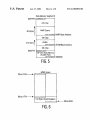
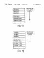
US 6,728,892 B1
9
10
speci?ed in the MnMIDH and MnMIDL registers associated
previously, the Acceptance Filtering process performed by
With that Message Object n. The user can mask any Screener
ID bits Which are not intended to be used in Acceptance
“match and mask” technique. The basic objective of this
Filtering, on an object-by-object basis, by Writing a logic ‘1’
in the desired (to-be-masked) bit position(s) in the appro
priate MnMSKH and/or MNMSKL registers associated With
each particular Message Object n. The user is responsible,
Acceptance Filtering process is to determine Whether a
Screener ID ?eld of the received CAN Frame (eXcluding the
“don’t care” bits masked by the Mask ?eld for each Message
Object) matches the Match ID of any enabled one of the 32
on set-up, for assigning a unique message buffer location for
each Message Object n. In particular, the user can specify the
least signi?cant 16 bits of the base address of the message
Message Objects that has been designated a Receive Mes
the XA-C3 microcontroller 20 can be characteriZed as a
10
buffer for each particular Message Object n by programming
the MnBLR register associated With that Message Object n.
The upper 8 bits of the 24-bit address, for all Message
Objects, are speci?ed by the contents of the MBXSR
register, as previously discussed, so that the message buffers
for all Message Objects reside Within the same 64 KByte
memory segment. The user is also responsible, on set-up, for
specifying the siZe of the message buffer for each Message
Object n. In particular, the user can specify the siZe of the
message buffer for each particular Message Object n by
programming the MnBSZ register associated With that Mes
sage Object n. The top location of the message buffer for
each Message Object n is determined by the siZe of that
message buffer as speci?ed in the corresponding MnBSZ
register.
sage Object. If there is a match betWeen the received CAN
Frame and more than one Message Object, then the received
CAN Frame Will be deemed to have matched the Message
Object
Acceptance
With theFiltering
loWest object
is performed
number as folloWs by the
XA-C3 microcontroller 20:
15
(1) A Screener ID ?eld is eXtracted from the incoming
(received) CAN Frame. In this regard, the Screener ID
?eld that is assembled from the incoming bit stream is
different for Standard and EXtended CAN Frames. In
particular, as is illustrated in FIG. 9, the Screener ID ?eld
for a Standard CAN Frame is 28 bits, consisting of 11
CAN ID bits eXtracted from the header of the received
CAN Frame +2><8 (16) bits from the ?rst and second data
bytes (Data Byte 1 and Data Byte 2) of the received CAN
Frame +the IDE bit. Thus, the user is required to set the
25
Mskl and Msk0 bits in the Mask Field (MnMSKL
register) for Standard CAN Frame Message Objects, i.e.,
The user can con?gure (program) the MnCTL register
associated With each particular Message Object n in order to
enable or disable that Message Object n, in order to de?ne
to “don’t care”. In addition, in many applications based on
Standard CAN Frames, either Data Byte 1, Data Byte 2,
or designate that Message Object n as a TX or RX Message
Object; in order to enable or disable automatic hardWare
or both do not participate in Acceptance Filtering. In those
assembly of fragmented RX messages (i.e., automatic frag
mented message handling) for that Message Object n; in
Byte(s). The IDE bit is not maskable. As is illustrated in
FIG. 10, the Screener ID ?eld for an EXtended CAN
order to enable or disable automatic generation of a
Frame is 30 bits, consisting of 29 CAN ID bits eXtracted
applications, the user must also mask out the unused Data
Message-Complete Interrupt for that Message Object n; and,
Remote Transmit Request (RTR) handling. In CANopen and
from the header of the incoming CAN Frame +the IDE
bit. Again, the IDE bit is not maskable.
(2) The assembled Screener ID ?eld of the received CAN
OSEK systems, the user must also initialiZe the MnFCR
Frame is then sequentially compared to the corresponding
register associated With each Message Object n.
Match ID values speci?ed in the MnMIDH and MnMIDL
in order to enable or not enable that Message Object n for
35
registers for all currently enabled Receive Message
As previously mentioned, on set-up, the user must con
?gure (program) the global GCTL register, Whose bits
control global parameters that apply to all Message Objects.
Objects. Of course, any bits in the Screener ID ?eld that
are masked by a particular Message Object are not
included in the comparison. That is, if there is a ‘1’ in a
In particular, the user can con?gure (program) the GCTL
register in order to specify the high-level CAL protocol (if
any) being used (e.g., DeviceNet, CANopen, or OSEK); in
order to enable or disable automatic acknowledgment of
45
CANopen Frames (CANopen auto-acknoWledge); and, in
care”, i.e., alWays yields a match With the corresponding
order to specify Which of tWo transmit (TX) pre-arbitration
schemes/policies is to be utiliZed (i.e., either TX pre
arbitration based on CAN ID, With the object number being
bit of the Screener ID of the received CAN Frame.
(3) If the above comparison process yields a match With
more than one Message Object, then the received CAN
Frame Will be deemed to have matched the Message
used as a secondary tie-breaker, or TX pre-arbitration based
on object number only).
Receive Message Objects and the Receive Process
During reception (i.e., When an incoming CAN Frame is
being received by the XA-C3 microcontroller 20), the CAN/
CAL module 77 Will store the incoming CAN Frame in a
Object having the loWest object number
Message Storage:
55
temporary (13-Byte) buffer, and determine Whether a
complete, error-free CAN frame has been successfully
Each incoming (received) CAN Frame that passes Accep
tance Filtering, Will be automatically stored, via the DMA
engine 38, into the message buffer for the Receive Message
Object that particular CAN Frame Was found to have
matched. In an eXemplary implementation, the message
buffers for all Message Objects are contained in the XRAM
28.
received. If it is determined that a complete, error-free CAN
Frame has been successfully received, then the CAN/CAL
module 77 Will initiate Acceptance Filtering in order to
Message Assembly:
determine Whether to accept and store that CAN Frame, or
to ignore/discard that CAN Frame.
In general, the DMA engine 38 Will transfer each accepted
CAN Frame from the 13-byte pre-buffer to the appropriate
Acceptance Filtering
In general, because the XA-C3 microcontroller 20 pro
vides the user With the ability to program separate Match ID
bit position of the Mask ?eld speci?ed in the MnMSKH
and Mn MSKL registers for a particular Message Object,
then the corresponding bit position in the Match ID ?eld
for that particular Message Object becomes a “don’t
65
message buffer (e.g., in the XRAM 28), one Word at a time,
starting from the address pointed to by the contents of the
and Mask ?elds for each of the 32 independent Message
MBXSR and MnBLR registers. Every time the DMA engine
Objects, on an object-by-object basis, as described
38 transfers a byte or a Word, it has to request the bus. In this