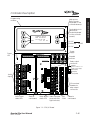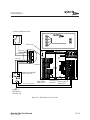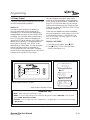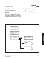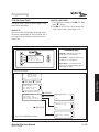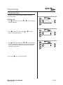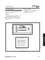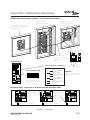
1
USER
GUIDE
Version 1J
9/20/00
INTELLIGENT LIGHTING CONTROLS, INC.
5229 Edina Industrial Boulevard
Minneapolis. Minnesota 55439
Phone 952 829 1900
FAX 952 829 1901
1-800-922-8004
Overview
The QUANTA Elite is a microprocessor-based programmable lighting controller. You can program
each of the controller inputs to control any or all of the relay outputs. The QUANTA Elite is UL and
FCC approved for commercial and residential applications.
Structure
The major components making up the
controller are:
• enclosure
• control transformer
• CPU I/O board
• additional I/O boards
• programming module
• lighting relays
Enclosure – The enclosure is rated NEMA 1.
It is divided into a line voltage section containing the line voltage side of the control
transformer and lighting relays and a low voltage section containing the Class 2 side of the
lighting relays, transformer secondaries and
electronic components. Enclosures are available in 6 sizes to accommodate 8, 16, 24, 32,
40 and 48 inputs, outputs, and lighting relays.
The QUANTA Elite is shipped to the job-site as
a complete assembly.
Transformer – A 40 VA multi-tap control transformer (120 or 277/24 VAC) provides the 24
VAC input to power the controller electronics.
CPU I/O Board – The CPU board provides
the controller’s intelligence and memory and
the first eight (8) of the controller inputs and
outputs. Major components include:
• Power Supply – converts the 24 VAC input
to the +5, -5 and +12 VDC required by the
controller logic and communications circuits.
A power switch provides the means of energizing/de-energizing all controller electronics.
Quanta Elite User Manual
Version 1J 9/20/00
• Micro-Processor – executes the computer
code and coordinates all controller functions
including the controller real time clock.
• PROM Chip – contains the controller
operating system and basic tasks.
• the EEPROM Chips – store the user-entered
operating parameters.
• “Super Cap” – keeps the controller real-time
clock functioning during power failures.
• Switch Inputs – can accept input from either
2- or 3-wire momentary or maintained dry
contact devices. Each input has two associated LEDs (light emitting diodes). The ON
LED lights when a closure is sensed between
the ON and COMMON terminals. The OFF
LED lights when a closure is sensed between
the OFF and COMMON terminals. The inputs
are noise- and surge-resistant. A switch may
be located up to 1500 feet from the controller, provided you use a minimum of 18
gauge wire.
• Relay Outputs – Each output switches its
associated lighting relay ON and OFF. Each
output has an associated LED. The LED lights
when the output switches the relay ON.
• Override Switches – Each relay output is
equipped with an ON and an OFF override
switch. These switches allow you to turn the
associated lighting relay ON or OFF.
• Stagger Start - The controller switches those
relays impacted by the same switch signal
ON/OFF, one at a time.
Table of Contents
Section 1 Controller Description
1.0 Section Overview ..........................................................................
1.1 Controller Architecture .................................................................
1.1.1 Enclosure................................................................................
1.1.2 Transformer ............................................................................
1.1.3 CPU I/O Board.......................................................................
1.1.4 Additional I/O Board(s) ........................................................
1.1.5 Programming Module ..........................................................
1.1.6 Lighting Relays.......................................................................
1.2 Controller Capacity.......................................................................
1.3 I/O Options .....................................................................................
1.3.1 Telephone Switching ............................................................
1.3.2 Pulsed Relay Output Operation..........................................
1.4 Programming with a PC................................................................
1.5 Expansion/Communications Options..........................................
1.6 DMX Option ....................................................................................
1.7 Enhanced Open/Close Time Control .........................................
1.8 N2 Communications......................................................................
1-1
1-2
1-2
1-2
1-2
1-2
1-3
1-3
1-3
1-8
1-8
1-8
1-8
1-8
1-8
1-8
1-8
Section 2 Installation
2.0 Section Overview ..........................................................................
2.1 Pre-Installation Checks ..................................................................
2.2 Mounting the Controller................................................................
2.2.1 Location .................................................................................
2.2.2 Environmental Considerations ............................................
2.2.3 Distance From Control Devices ..........................................
2.3 Wiring the Controller......................................................................
2.3.1 Wire the Control Transformer...............................................
2.3.2 Connect Line and Load ......................................................
2.3.3 Wire Switch Inputs .................................................................
2.3.4 Set Relay Response ..............................................................
2.4 Pre-Power Checks..........................................................................
2.4.1 Check Controller Power Input.............................................
2.4.2 Verify Controller’s Supply Voltage.......................................
2.4.3 Double-Check Connections ...............................................
2.5 Power-Up and Check Out............................................................
2.5.1 Power-Up the Controller ......................................................
2.5.2 Verify the Lighting Relays .....................................................
2.5.3 Perform Initial Programming Procedures ...........................
2.5.4 Verify the Switching Function ..............................................
2.5.5 Verify the Timer Functions ....................................................
2-1
2-2
2-2
2-2
2-2
2-2
2-2
2-2
2-2
2-2
2-2
2-5
2-5
2-5
2-5
2-5
2-5
2-5
2-5
2-5
2-5
Quanta Elite User Manual
Version 1J 9/20/00
Table of Contents
Section 2 Installation, continued
2.6 Troubleshooting..............................................................................
2.6.1 Controller Will Not Power-Up ...............................................
2.6.2 Lighting Relay(s) Will Not Function......................................
2.6.3 Switch Input Will Not Function.............................................
2.6.4 Timers Will Not Function Properly ........................................
2.6.5 Entire I/O Board(s) Doesn’t Work ........................................
2-6
2-6
2-6
2-6
2-6
2-6
Section 3 Programming
3.0 Section Overview ..........................................................................
3.1 Relay Status ....................................................................................
3.2 Controlling Relays From the Keypad...........................................
3.3 Relay Output ..................................................................................
3.4 Set Relay Parameters ....................................................................
3.5 Switch Status...................................................................................
3.6 View Current Switch Status...........................................................
3.7 Switch Input ....................................................................................
3.8 Programming a Switch Input........................................................
3.9 Input/Relay Control .......................................................................
3.10 Map a Switch to a Relay Output...............................................
3.11 Timers .............................................................................................
3.12 Define a Timer ..............................................................................
3.13 Timer/Relay Control .....................................................................
3.14 Map the Timer to a Relay Output .............................................
3.15 Blink Alerts .....................................................................................
3.16 Set Time and Date.......................................................................
3.17 Set the Controller Clock..............................................................
3.18 Set Astro Clock .............................................................................
3.19 Daylight Savings Time..................................................................
3.20 Serial Interface .............................................................................
3.21 Telephone Interface....................................................................
3.22 DMX Receiver...............................................................................
3.23 Panel Name..................................................................................
3.24 Edit Presets ....................................................................................
3.25 Capture Preset .............................................................................
3.26 Set Open/Close Times.................................................................
3.26.1 Example: Set Open/Close Times.......................................
3.26.2 Example: Define the Timers ...............................................
3.26.3 Example: Map Lighting Relays to Timers..........................
3.27 Firmware Revision ........................................................................
3-1
3-2
3-3
3-4
3-5
3-6
3-7
3-8
3-9
3-11
3-12
3-13
3-16
3-17
3-18
3-19
3-21
3-22
3-23
3-25
3-27
3-28
3-29
3-30
3-32
3-34
3-36
3-37
3-38
3-39
3-40
Quanta Elite User Manual
Version 1J 9/20/00
Table of Contents
Section 4 Appendix
A. Telephone Add-On Module...........................................................
A.1 Overview ..................................................................................
A.2 Telephone Control Features ..................................................
A.3 Telephone Control Setup .......................................................
A.4 Remote Modem Programming Control
and Monitoring........................................................................
A.5 Remote Modem Control Setup.............................................
A-2
A-2
B. PC Add-On Module ........................................................................
B.1 Overview...................................................................................
B.2 PC Add-On Setup....................................................................
B-1
B-1
B-1
C. Master/Slave Networking...............................................................
C.1 Overview..................................................................................
C.2 Setup ........................................................................................
C.3 Installation ................................................................................
C.4 Power-Up .................................................................................
C.5 Programming...........................................................................
C-1
C-1
C-1
C-1
C-1
C-3
D. DMX Control Feature ......................................................................
D.1 Overview ..................................................................................
D.2 Objectives ................................................................................
D.3 Programming Example...........................................................
D-1
D-1
D-1
D-3
E. Master Scheduler .............................................................................
E.1 Objectives.................................................................................
E.2 Overview...................................................................................
E.3 Description................................................................................
E.4 Installation .................................................................................
E.5 Programming OPEN/CLOSE Schedules.................................
E-1
E-1
E-1
E-3
E-3
E-4
M. MODBUS Communications............................................................
M.1 Overview .................................................................................
M.2 Structure...................................................................................
M.3 Transmission Modes ................................................................
M.4 Transmission Mode Characteristics.......................................
M.5 Hardware Setup......................................................................
M.6 Required Parameter Entries...................................................
M.7 Framing ....................................................................................
M.8 Supported Commands ..........................................................
M.9 Additional Information...........................................................
M-1
M-1
M-1
M-1
M-3
M-3
M-3
M-3
M-3
M-3
N. N2 Communications .......................................................................
N.1 Overview ..................................................................................
N.2 Hardware Setup ......................................................................
N.3 Point Map.................................................................................
Quanta Elite User Manual
N-1
N-1
N-1
N-1
Version 1J 9/20/00
A-1
A-1
A-2
A-2
Controller Description
EDIT
Quanta Elite User Manual
Version 1J 9/20/00
QUANTA ELITE
WED 02/28/01
07:50:54 PM
(C) 01 ILC
Controller Description
Section 1
Controller Description– Table of Contents
Section 1 Controller Description
1.0 Section Overview ..........................................................................
1-1
1.1 Controller Architecture .................................................................
1.1.1 Enclosure................................................................................
1.1.2 Transformer ............................................................................
1.1.3 CPU I/O Board.......................................................................
1.1.4 Additional I/O Board(s) ........................................................
1.1.5 Programming Module ..........................................................
1.1.6 Lighting Relays.......................................................................
1-2
1-2
1-2
1-2
1-2
1-3
1-3
1.2 Controller Capacity.......................................................................
1-3
1.3 I/O Options .....................................................................................
1.3.1 Telephone Switching ............................................................
1.3.2 Pulsed Relay Output Operation..........................................
1-8
1-8
1-8
1.4 Programming with a PC................................................................
1-8
1.5 Expansion/Communications Options..........................................
1-8
1.6 DMX Option ....................................................................................
1-8
1.7 Enhanced Open/Close Time Control .........................................
1-8
1.8 N2 Communications......................................................................
1-8
Quanta Elite User Manual
Version 1J 9/20/00
Section 1.0 – Controller Description
Overview
In this Section you will learn about the structure and configuration of the QUANTA Elite
Controller.
The QUANTA Elite is a microprocessor-based
lighting controller. You can program the
QUANTA Elite to control lighting relays in
response to switch signals sensed by its
inputs and/or by time-based scheduling.
The QUANTA Elite is UL approved and FCC
certified for both commercial and
residential applications.
Quanta Elite User Manual
Version 1J 9/20/00
1-1
Controller Description
Objectives
Controller Description
1.1 Controller Architecture
The major components making up the
controller are: (See Figure 1.1.)
• enclosure
• control transformer
• CPU I/O board
• additional I/O boards
• programming module
• lighting relays
1.1.1 Enclosure – The enclosure is rated
NEMA 1. It is divided into a line voltage section containing the line voltage side of the
control transformer and lighting relays and
a low voltage section containing the Class 2
side of the lighting relays, transformer secondary, and electronic components.
Enclosures are available in 6 sizes to accommodate 8, 16, 24, 32, 40 and 48 inputs, outputs, and lighting relays. (See Table 1-1.) The
QUANTA Elite is shipped to the job-site as a
complete assembly. (See Figure 1-1 which
illustrates QUANTA Elite 8.)
1.1.2 Transformer – A 40 VA multi-tap control
transformer (120 or 277/24 VAC) provides
the 24 VAC input to power the controller
electronics.
1.1.3 CPU I/O Board – (See Figure 1.2.) The
CPU board provides the controller’s intelligence and memory and the first eight (8) of
the controller inputs and outputs. Major
components include:
• Power supply – converts the 24 VAC input
to the +5, -5 and +12 VDC required by
the controller logic and communications
circuits. A power switch provides the
means of energizing/de-energizing all
controller electronics.
Quanta Elite User Manual
Version 1J 9/20/00
• Micro-Processor – executes the computer
code and coordinates all controller functions, including the controller real-time
clock.
• PROM Chip – contains the controller operating system and basic tasks.
• EEPROM Chips – store the user-entered
operating parameters.
• “Super Cap” – keeps the controller real-time
clock functioning during power failures.
• Switch Inputs - can accept input from either
2- or 3-wire momentary or maintained dry
contact devices. Each input has two associated LEDs. The ON LED lights when a closure is sensed on the ON and COMMON
terminals. The OFF LED lights when a closure
is sensed on the OFF and COMMON terminals. The inputs are noise- and surge-resistant. A switch may be located up to 1500
feet from the controller, provided a minimum of 18 gauge wire is used.
• Relay Outputs - Each output switches its
associated lighting relay ON and OFF.
Each output has an associated LED (light
emitting diode). The LED lights when the
output switches the relay ON.
• Override Switches - Each relay output is
equipped with an ON and an OFF override
switch. These switches allow you to turn the
associated lighting relay ON or OFF.
1.1.4 Additional I/O Board(s) – Additional
I/O boards composed of 8 inputs and 8 outputs can be added to the appropriate size
enclosure to expand the controller capacity
up to 48 switch inputs and 48 switch relay
outputs. (See Figure 1.3, which illustrates a
QUANTA Elite 32.)
1-2
Controller Description
120 or 277 VAC loads rated up to 20 amps.
The Class 2 low voltage control part of each
relay is terminated to a relay output on the
controller CPU I/O board. (See Figure 1.2.)
Each relay output controls only one lighting
relay.
1.2 Controller Capacity
Unless you have ordered optional communications/expansion features, each QUANTA
Elite can control up to 48 programmable
switched inputs and 48 relay outputs.
1.1.6 Lighting Relays – control the line voltage loads. The lighting relays can control
Model
# of Relays &
I/O Points
Width
Height
Depth
Elite 8
8
18 inches
15 inches
4 inches
Elite 16
16
24 inches
18 inches
4 inches
Elite 24
24
24 inches
36 inches
4 inches
Elite 32
32
24 inches
36 inches
4 inches
Elite 40
40
24 inches
48 inches
6 inches
Elite 48
48
24 inches
48 inches
6 inches
Table 1.1 – QUANTA Elite Configurations
Quanta Elite User Manual
Version 1J 9/20/00
1-3
Controller Description
1.1.5 Programming Module – (See Figure
1.4.) The programming module provides
you with access to program and view controller data. It consists of a tactile response
keypad and screen. The programming
module is either mounted to the CPU I/O
board or at your option can be a separate
hand-held portable device that you can
temporarily connect during programming
and then detach.
Controller Description
Grounding Lug
Control transformer
Enclosure
2
1
4
3
6
5
8
7
CPU I/O
board
Lighting relays
Programming module
CONNECTOR
ORANGE
ORANGE
}STATUS
BLACK (OFF)
RED (ON)
BLUE (COM)
Relay termination detail
Figure 1.1 – QUANTA Elite 8 Controller
Quanta Elite User Manual
Version 1J 9/20/00
1-4
Controller Description
Programming
module
W1
ON
EDIT
QUANTA ELITE
WED 02/28/01
07:50:54 PM
(C) 01 ILC
OFF
12 VAC
Center tap
12 VAC
24 VAC
Power
supply
Power
LED
Override
switches
Relay output
connector
1ON
1OFF
OFF
ON
COM
1
2 ON
2 OFF
2
3 ON
1 2
3 OFF
Switch
inputs
Terminal block for
transformer
(under Keyboard
on the controller
board )
3
COM
Orange
(Aux. contacts : not
used on 2R7 relay)
Black (OFF)
Red (ON)
Blue (COM)
4 ON
4
4 OFF
3 4
5 ON
5
5 OFF
COM
6 ON
6
5 6
6 OFF
7 ON
7
7 OFF
COM
8
8 ON
OFF
PILOT
COM +
8 OFF
Switch input
status LEDs
ON
Data to
next board
Relay output Status Terminals
status LEDs
(used with Pilot
Light Switches)
I/O mounted
headers for
relay output
connectors
7 8
V10
Pilot
COM
Power to
next board
Figure 1.2 – CPU I/O Board
Quanta Elite User Manual
Version 1J 9/20/00
1-5
Controller Description
Main power
switch (under
Keyboard on the
controller board )
Controller Description
2
1
4
3
6
5
8
7
10
9
11
12
14
13
16
15
18
17
20
Additional
I/O boards
19
22
21
24
23
26
25
28
27
30
29
32
31
Figure 1.3 – QUANTA Elite 32
Quanta Elite User Manual
Version 1J 9/20/00
1-6
Controller Description
Controller Description
4-line, 32-character Display Screen
Selection Keys
(used to select
displayed options)
Quanta Elite User Manual
Version 1J 9/20/00
Scrolling Pads
Figure 1.4 – Elite Keypad and Display
1-7
Controller Description
1.3 I/O Options
1.6 DMX Option
If your application requires, you can equip
the controller with certain input/output
options.
You can equip the QUANTA Elite with a DMX
interface to control the non-dimmed loads
that are part of a theatrical lighting control
system. Consult factory if this option is
applicable to your situation.
1.3.1 Telephone Switching – You can equip
the controller with a DTMF (Dual Tone Multi
Frequency) interface, which allows you to
activate switch inputs via commands from
a touchtone telephone. See Appendix A.
1.3.2 Pulsed Relay Output Operation – By
adding conversion hardware to the relay
outputs, you can convert the output from
a maintained output to a pulsed output
required for control of mechanically
latching contactors and other devices
that operate on a momentary rather than
maintained application of power. Consult
factory for details.
1.7 Enhanced Open/Close Time
Control
If your control requirements call for timebased control keyed to multiple sets of
Open/Close times, see Appendix E. – Master
Scheduler.
1.8 N2 Communications
You can configure the QUANTA Elite as a
node on a Building Automation System
(BAS) N2 Communications Network. See
Appendix N.
1.4 Programming with a PC
If you want to program the controller with a
personal computer equipped with QUANTA
Pro software, see Appendix B.
1.5 Expansion/Communications
Options
With the addition of enhanced software
and interface hardware, you can develop
a LAN (local area network) composed of
up to 256 nodes, each node controlling up
to 48 I/O points. Consult Appendix C in this
manual if your application requires expansion/networking.
If you want to program the controller over
phone lines via a remote personal computer equipped with QUANTA Pro software, see
Appendix A.
Quanta Elite User Manual
Version 1J 9/20/00
1-8
Section 2
Installation
Installation
EDIT
Quanta Elite User Manual
Version 1J 9/20/00
QUANTA ELITE
WED 02/28/01
07:50:54 PM
(C) 01 ILC
Installation – Table of Contents
Section 2 Installation
2.0 Section Overview ..........................................................................
2-1
2.1 Pre-Installation Checks ..................................................................
2-2
2.2 Mounting the Controller................................................................
2.2.1 Location .................................................................................
2.2.2 Environmental Considerations ............................................
2.2.3 Distance From Control Devices ..........................................
2-2
2-2
2-2
2-2
2.3 Wiring the Controller......................................................................
2.3.1 Wire the Control Transformer...............................................
2.3.2 Connect Line and Load ......................................................
2.3.3 Wire Switch Inputs .................................................................
2.3.4 Set Relay Response ..............................................................
2-2
2-2
2-2
2-2
2-2
2.4 Pre-Power Checks..........................................................................
2.4.1 Check Controller Power Input.............................................
2.4.2 Verify Controller’s Supply Voltage.......................................
2.4.3 Double-Check Connections ...............................................
2-5
2-5
2-5
2-5
2.5 Power-Up and Check Out............................................................
2.5.1 Power-Up the Controller ......................................................
2.5.2 Verify the Lighting Relays .....................................................
2.5.3 Perform Initial Programming Procedures ...........................
2.5.4 Verify the Switching Function ..............................................
2.5.5 Verify the Timer Functions ....................................................
2-5
2-5
2-5
2-5
2-5
2-5
2.6 Troubleshooting..............................................................................
2.6.1 Controller Will Not Power-Up ...............................................
2.6.2 Lighting Relay(s) Will Not Function......................................
2.6.3 Switch Input Will Not Function.............................................
2.6.4 Timers Will Not Function Properly ........................................
2.6.5 Entire I/O Board(s) Doesn’t Work ........................................
2-6
2-6
2-6
2-6
2-6
2-6
Quanta Elite User Manual
Version 1J 9/20/00
Installation
Objectives
Overview
This sections shows you how to install the
QUANTA Elite Controller and how to perform
required power-up verification checks. This
section covers installation of the basic 48
I/O stand-alone controller. For information
on optional features or communication/LAN
systems, consult the appropriate appendix.
This section covers the following topics:
• Pre-installation checks
• Mounting the controller
• Wiring the controller
• Pre-power-up checks
• Power-up and checkout
• Troubleshooting
Installation
Quanta Elite User Manual
Version 1J 9/20/00
2-1
Installation
2.1 Pre-Installation Checks
Do the following before beginning the
installation:
1. Verify that you have received the proper
equipment. Check the packing slip
against the materials you ordered and
verify that the material is appropriate for
the project. Check to ensure that the
voltages of the controller(s) transformers
match the available power. Report any
discrepancies or visible damage at once.
2. Review submittal, programming worksheets, electrical prints, and other project
documentation.
3. Ensure that you have a digital multi-meter.
2.2 Mounting the Controller
Consider the following when selecting a site
for the QUANTA Elite.
2.2.1 Location – Typically, the QUANTA Elite
controller is mounted near the lighting
panel containing the circuits to be controlled by the lighting relays. The enclosure is
manufactured with pre-drilled mounting
holes located near the four corners of the
rear wall of the enclosure. Secure the enclosure to the mounting surface with hardware
appropriate for the application.
2.2.2 Environmental Considerations –
The QUANTA Elite is designed to operate
in temperatures between 0 and 50 degrees
C (32-112°F.) and10%-90% humidity
non-condensing.
CAUTION
THE QUANTA ELITE SERIES CONTROLLER IS
HOUSED IN A NEMA 1 ENCLOSURE. DO
NOT INSTALL IN SITUATIONS REQUIRING
SPECIAL PURPOSE ENCLOSURES OR IN
AREAS WHERE THE CONTROLLER WILL BE
SUBJECT TO CONDITIONS OUTSIDE ITS
DESIGNED OPERATING RANGES.
Quanta Elite User Manual
Version 1J 9/20/00
2.2.3 Distance From Control Devices
Switches and other control devices can be
located up to 1500 feet from the QUANTA
Elite controller using 18 gauge wire.
2.3 Wiring the Controller
Perform the following procedures to wire
the line and control circuits of the QUANTA
Elite. Do NOT apply power to any circuits
until instructed to do so.
2.3.1 Wire the Control Transformer
Run a dedicated 120 or 277 VAC circuit,
including grounding conductor, and terminate it to the primary of QUANTA Elite control transformer. (See Figure 2.1.)
2.3.2 Connect Line and Load – Connect line
and load wires of the line voltage circuits to
the Lighting Relays.
2.3.3 Wire Switch Inputs - Wire the Class 2
Switch Circuits. (See Figure 2.2.)
1. Run the required wiring between the
controller and the field-installed switches.
Consult the programming worksheets and
project documentation to determine the
type and quantity of required switch
circuits. Check each switch run to ensure
that there are no shorts between
conductors or to ground. Also verify that
there are no opens.
2. Make the connections at the switch end.
3. Make the connections to the controller
switch input terminals. (N0TE: REFER TO
SWITCH INPUT SCHEDULE FOR LANDING
WIRES TO INPUTS OR FILL IN SWITCH
SCHEDULE AS YOU PROCEED.)
2.3.4 Set Relay Response
If you want all relays to respond to a
signal instantaneously rather than to
stagger ON/OFF one at a time, add jumper
W1 on the CPU I/O board. (See Figure 2.1.)
2-2
Installation
Jumper W1- Relay response (on
I/O board under programming
module)
Grounding Lug
Green
Grounding
Conductor
Brown
(277 VAC Hot)
White
(Neutral)
2
Black
(120 VAC Hot)
1
4
Installation
3
6
5
8
7
Figure 2.1 – Terminate Line to Control
Transformer Primary
Quanta Elite User Manual
Version 1J 9/20/00
2-3
Installation
Typical maintained switch
W1
Power LED
1ON
ON (Red)
COM (Yellow)
1OFF
COM
2 ON
1ON
2 OFF
ON (Red)
OFF (Black)
COM (Yellow)
1OFF
3 ON
OFF
ON
COM
2 ON
3 OFF
2 OFF
3 ON
1 2
3 OFF
COM
4 ON
4 OFF
3 4
5 ON
5 OFF
COM
6 ON
Typical momentary
switch with LED
5 6
6 OFF
7 ON
7 OFF
COM
8 ON
OFF
LED Common (Grey)
Switch input
Status LEDs
ON
PILOT
COM +
8 OFF
Override
switches
7 8
V10
Relay output
Status LEDs
LED (Orange) to LED terminal of relay controlled
Applies to
pilot lighted
switches only
Figure 2.2 – Wire Class 2 Switch Circuits
Quanta Elite User Manual
Version 1J 9/20/00
2-4
Installation
2.4 Pre-Power Checks
2.5 Power-Up and Check Out
Complete the following checks BEFORE
applying power to the QUANTA Elite
controller.
Complete the following procedures to
power-up and check out the QUANTA Elite
controller.
2.4.1 Check Controller Power Input
1. Verify that the controller power switch
is OFF.
2. After verifying that control transformer
source voltage is 120 or 277 VAC
(whichever is appropriate), power-up
the circuit.
3. Verify correct line voltage on the
primary of the transformer.
2.5.1 Power-Up the Controller
1. Connect a handheld programming
module if working with a QUANTA Elite
that doesn’t have an onboard keypad.
2. Turn the power switch located on the
CPU I/O board ON. (See Figure 1.2.)
3. Verify that the controller keypad screen
displays the default time and date.
4. Verify that the power light on each I/O
board is lit. (See Figure 2.2.)
2.4.3 Double-Check Connections
1. Verify integrity of I/O connections.
2. Verify integrity of all internal and external
wire/cabling.
2.5.2 Verify the Lighting Relays
Switch each relay ON and OFF, pushing the
override switches located on the CPU I/O
and the other I/O boards. There are separate ON and OFF switches for each lighting
relay. (See Figure 2.2.) Verify that the relay
status LED goes ON and OFF and that the
relay itself changes state. Verify that the
relay controls the proper circuit.
2.5.3 Perform Initial Programming
Procedures (See Section 3.)
1. Set the correct date & time on the
controller.
2. Program the switch inputs & timers.
2.5.4 Verify the Switching Function
1 .Operate each switch.
2. Verify that each switch controls the
correct lighting relays in the manner you
have programmed.
2.5.5 Verify the Timer Functions –
1. Set the controller clock 10 minutes
prior to the times required for each
programmed timer to occur.
2. Verify that the relays respond as
programmed.
3. Reset the controller clock to the correct
date and time.
Quanta Elite User Manual
Version 1J 9/20/00
2-5
Installation
2.4.2 Verify Controller’s Supply Voltage
Verify that there is 24 VAC on control
transformer secondary and 12 VAC
between each leg and the center tap. (See
Figure 1.2.)
Installation
2.6 Troubleshooting
In the event of trouble, use the following
procedures to identify the problem.
2.6.1 Controller Will Not Power-Up
1. Verify that there is 120/277 VAC on the
primary and 24 VAC on the secondary of
the control transformer.
2. Verify that the power LED on the CPU I/O
board is lit.
3. If there is proper primary and secondary
voltage on the transformer but the power
LED is not lit and the keypad screen
doesn’t come up, the controller CPU I/O
board may be defective.
2.6.2 Lighting Relay(s) Will Not Function
1. Verify that there is 24 VAC on Control
Transformer secondary.
2. Make sure that lighting control wiring is
landed properly on the relay output of
the CPU I/O or other I/O boards. (Blue is
common, red is ON, black is OFF, orange
is status.) (See Figure 1.1.)
3. Override the affected relay ON/OFF with
the override switches located on the I/O
board. (See Figure 1.2.)
4. If the relay doesn’t respond, replace
the relay.
2.6.3 Switch Input Will Not Function
1. Check your programming.
2. Verify proper connections at field and
controller end.
3. Verify that there is only one maintained
switch connected per input.
4. Unhook field connections from affected
input. Connect test switch of same type
as field switch.
5. Work the test switch. Observe whether
the switch input status LED lights when it
senses a switch closure.
6. If the switch input status LED lights and
the relays function properly, there is probably a problem with the field wiring.
Quanta Elite User Manual
Version 1J 9/20/00
7. Verify that the CPU is seeing the switch
input by viewing the current switch status.
This can be done with the keypad by
going to the Switch Status screen and
scrolling to the individual input or scanning
all of the inputs to verify that a switch closure is being seen by the controller (stepby-step procedure is on page 3 - 6). Also
the outputs of the CPU and I/O boards can
be tested through the keypad. Relays can
be forced individually or all swept ON or
OFF using the keypad (a step-by-step procedure can be followed on page 3 - 3).
8. If the switch input or affected relay
doesn’t respond (or no response is
viewed through the keypad), the affected CPU or I/O may be defective.
2.6.4 Timers Will Not Function Properly
1. Check your programming.
2. Verify the affected output integrity by
mapping a switch input to the output
and triggering it with a test switch. If the
relay doesn’t react, you may have a
defective I/O board. Consult factory.
2.6.5 Entire I/O Board(s) Doesn’t Work
1. Check to ensure that the data and
power cables linking the I/O boards are
connected properly and are free of
opens and shorts.
2. Check to ensure that the power LED on
the I/O board is lit.
3. Verify that the CPU sees the expansion
I/O boards, using the keypad. This can be
done by going to the Relay Status screen
and scrolling through the outputs to see if
the CPU sees all of the outputs (a step-bystep procedure is on page 3 - 3).
4. If the I/O board is not recognized by the
CPU, you may have a defective board or
data cable.
2-6
Section 3
Programming
EDIT
QUANTA ELITE
WED 02/28/01
07:50:54 PM
(C) 01 ILC
Programming
Quanta Elite User Manual
Version 1J 9/20/00
Programming – Table of Contents
Section 3 Programming
3.0 Section Overview ..........................................................................
3-1
3.1 Relay Status ....................................................................................
3-2
3.2 Controlling Relays From the Keypad...........................................
3-3
3.3 Relay Output ..................................................................................
3-4
3.4 Set Relay Parameters ....................................................................
3-5
3.5 Switch Status...................................................................................
3-6
3.6 View Current Switch Status...........................................................
3-7
3.7 Switch Input ....................................................................................
3-8
3.8 Programming a Switch Input........................................................
3-9
3.9 Input/Relay Control .......................................................................
3-11
3.10 Map a Switch to a Relay Output...............................................
3-12
3.11 Timers .............................................................................................
3-13
3.12 Define a Timer ..............................................................................
3-16
3.13 Timer/Relay Control .....................................................................
3-17
3.14 Map the Timer to a Relay Output .............................................
3-18
3.15 Blink Alerts .....................................................................................
3-19
3.16 Set Time and Date.......................................................................
3-21
3.17 Set the Controller Clock..............................................................
3-22
3.18 Set Astro Clock .............................................................................
3-23
3.19 Daylight Savings Time..................................................................
3-25
3.20 Serial Interface .............................................................................
3-27
3.21 Telephone Interface....................................................................
3-28
3.22 DMX Receiver...............................................................................
3-29
3.23 Panel Name..................................................................................
3-30
3.24 Edit Presets ....................................................................................
3-32
3.25 Capture Preset .............................................................................
3-34
3.26 Set Open/Close Times.................................................................
3.26.1 Example: Set Open/Close Times.......................................
3.26.2 Example: Define the Timers ...............................................
3.26.3 Example: Map Lighting Relays to Timers..........................
3-36
3-37
3-38
3-39
3.27 Firmware Revision ........................................................................
3-40
Quanta Elite User Manual
Version 1J 9/20/00
Programming
Objectives
In this section you will learn how to program the
QUANTA Elite Controller.
Conventions/Definitions
Actual key strokes/entries appear as arrows: for
example, followed (if applicable) by the
appropriate keyword. For example, to leave
the Home screen, the entry is EDIT. (See the
figure below.)
The term default appears in this section. Default
means the value or entry preprogrammed at
the factory. In many cases the default may be
appropriate for your application, making field
programming unnecessary. For example,
momentary ON/OFF is the default switch type;
therefore, if 3-wire momentary switches are
used exclusively at your facility, switch input
definition will not be necessary.
Automatic Timeout/Data Saving
If you do not press any keys for 30 seconds
while you are programming, the controller will
automatically return to the Home screen and
save whatever data was entered. Therefore
you can save entries simply by stopping
keystrokes or by entering the proper keyword –
usually EXIT or SAVE.
Programming
EDIT
Another term used often is Home screen. The
Home screen is the top level screen of the controller. It features the controller name, the date
and the time. (See Figure 3.1.) The controller
displays this screen on power-up and at times
when you are not programming or checking
input/output status.
QUANTA ELITE
WED 02/28/01
07:50:54 PM
(C) 01 ILC
Figure 3.1 - QUANTA Elite Home Screen
Quanta Elite User Manual
Version 1J 9/20/00
3 -1
Programming
3.1 Relay Status
HOW DO I GET THERE?
View current relay status or turn relay(s) ON or
OFF directly from the keypad.
WHAT IS IT?
This feature permits you to view the current
ON/OFF state of the relay outputs. In addition,
you can turn a selected relay ON or OFF or
you can turn all the relays ON or OFF.
1. From the Home screen, press EDIT.
2. Then press RELAY STATUS to access the
top level Relay Status screen.
(See Figure 3.2.)
Parameter Key:
ON = turn the selected relay ON
ON
OFF
SWEEP
EXIT
RELAY: 01
IS OFF
OFF = turn the selected relay OFF
SWEEP = turn ALL RELAYS ON or
ALL RELAYS OFF
Top Level Relay Status Screen
EDIT
QUANTA ELITE
WED 10/14/98
07:50:54 PM
(C) 98 ILC
EDIT
EXIT
RELAY STATUS
RELAY OUTPUT
SWITCH STATUS
RELAY STATUS
ON
OFF
SWEEP
EXIT
RELAY:01
IS OFF
Relay Status
Screen Flow
Figure 3.2
Quanta Elite User Manual
Version 1J 9/20/00
3-2
Programming
3.2 Controlling Relays From the Keypad
WHAT DO I DO?
1. From the Home screen, press EDIT.
EDIT
QUANTA ELITE
WED 10/14/98
07:50:54 PM
(C) 98 ILC
Step 1
RELAY STATUS
RELAY OUTPUT
SWITCH STATUS
SWITCH INPUT
2. Press RELAY STATUS.
Step 2
until the relay to be overridden appears on
3. Press
the screen.
ON
OFF
SWEEP
EXIT
4. Press either ON or OFF to override the relay to
the desired state.
RELAY: 01
IS OFF
Steps 3 & 4
6. Press EXIT to return to the top level Relay Status
screen.
Programming
5. To turn all the relays ON or OFF, press SWEEP; then
press either ALL RELAYS ON or ALL RELAYS OFF.
ON
RELAY: 01
ALL RELAYS ON
ALL RELAYS OFF
EXIT
Step 5
7. Press EXIT to return to the Home screen.
Quanta Elite User Manual
Version 1J 9/20/00
3-3
Programming
3.3 Relay Output
Configure relay output properties such as Blink
functions and power-up options.
WHAT IS IT?
Use relay output definition to determine
the way each relay output responds to
impending OFF timers and the application/
re-application of power to the QUANTA Elite
controller. The controller blinks (momentarily
turns OFF/ON each relay controlled by an
upcoming OFF) as a warning. (NO BLINK is the
default entry.) Blinking is not appropriate for
some types of lighting, such as HID. As an
alternative to a blink alert, you can program
one of the relay outputs to energize an
ALARM external to the controller. The alarm
sounds when a relay defined for an HID DELAY
is about to be turned OFF by a timer.
You can program how each relay output
responds to the application or re-application
of AC power to the controller. The default setting is NO ACTION (the relay will not change
state on controller power-up). The other choices are for the relay to TURN ON or TURN OFF on
controller power-up.
There are two additional choices available.
You can program the relay output to turn ON
if switch input number 1 is ON (ON/IN:1) or
turn OFF (OFF/IN:1) if switch input 1 is ON at
time of power-up.
HOW DO I GET THERE?
1. From the Home screen, press EDIT.
2. Press RELAY OUTPUT from the Menu
screen. (See Figure 3.3.)
EDIT
RELAY
TIMERS
POWERUP
EXIT
RELAY: 01
NO BLINK
NO ACTION
QUANTA ELITE
WED 10/14/98
07:50:54 PM
(C) 98 ILC
EDIT
EXIT
RELAY STATUS
RELAY OUTPUT
SWITCH STATUS
RELAY OUTPUT
RELAY
TIMERS
POWERUP
EXIT
Relay Output Definition Screen
RELAY: 01
BLINK
NO ACTION
Relay Output Definition Screen
Parameter Key:
TIMER = relay output to be defined (1 – 48)
TIMERS = how the relay will respond to an impending timer. Default is NO BLINK. Other possible
entries: BLINK, HID DISPLAY, ALARM
POWERUP = how the relay responds to application or re-application of controller power. Default
is NO ACTION
Figure 3.3
Quanta Elite User Manual
Version 1J 9/20/00
3-4
Programming
3.4 Set Relay Parameters
WHAT DO I DO?
NOTE: The default parameters are for the relays to not
blink alert an upcoming OFF timer and take no action
on controller power-up. If these are appropriate for the
application, you can skip this section.
1. From the Home screen, press EDIT; then press
RELAY OUTPUT.
2. RELAY appears; then press
to define appears.
until the relay you want
RELAY
TIMERS
POWERUP
EXIT
RELAY: 01
NO BLINK
NO ACTION
RELAY
TIMERS
POWERUP
EXIT
RELAY: 01
NO BLINK
NO ACTION
Step 2
3. Press TIMERS; then press
until the desired
response of the relay to an upcoming OFF timer
appears.
Step 3
RELAY
TIMERS
POWERUP
EXIT
Programming
4. Press POWERUP until the desired relay response to
a controller powerup appears.
RELAY: 01
NO BLINK
NO ACTION
Step 4
5. Press EXIT twice to return to the Home screen.
Quanta Elite User Manual
Version 1J 9/20/00
3-5
Programming
3.5 Switch Status
View current switch input status for any switch
input or scan all switch inputs.
OPEN when the switch is in the neutral position. During actuation, a momentary OPEN or
CLOSED message displays on the screen if the
currently selected input is actuated.
WHAT IS IT?
You can view the current status of each switch
input. The Switch Status screen will display
maintained switch inputs as either OPEN or
CLOSED. Momentary inputs are displayed as
HOW DO I GET THERE?
1. From the Home screen, press EDIT.
2. Press SWITCH STATUS to access the Switch
Status screen. (See Figure 3.4.)
HOLD
SCAN
INPUT: 01
ON: CLOSED
OFF: OPEN
EXIT
Switch Status Screen
EDIT
QUANTA ELITE
WED 10/14/98
07:50:54 PM
(C) 98 ILC
EDIT
EXIT
RELAY STATUS
RELAY OUTPUT
SWITCH STATUS
SWITCH STATUS
HOLD
SCAN
INPUT: 01
ON: CLOSED
OFF: OPEN
EXIT
Switch Status Definition Screens
Figure 3.4
Quanta Elite User Manual
Version 1J 9/20/00
3-6
Programming
3.6 View Current Switch Status
WHAT DO I DO?
1. Press HOLD; then press
you want to check.
or to select the input
2. If you press SCAN while viewing an input, the
controller will automatically display the input that
has changed state.
HOLD
SCAN
INPUT:01
ON:CLOSED
OFF:OPEN
EXIT
Step 1
3. Press EXIT to leave the screen.
Programming
Quanta Elite User Manual
Version 1J 9/20/00
3-7
Programming
3.7 Switch Input
gram each input as one of the available
switch types. Consult Table 3.1 for a description
of each switch type and the required physical
characteristics of the switch used to trigger the
switch type function.
Configure the switch type for switch inputs
WHAT IS IT?
Switch input is used to program the characteristics of each QUANTA Elite controller input.
Each of the controller inputs can be connected to either a 2-wire and 3-wire momentary
switch or to maintained switch(s). You can pro-
HOW DO I GET THERE?
1. From the Home screen, press EDIT;
then press .
2. Press SWITCH INPUT. (See Figure 3.5.)
Parameter Key:
INPUT
TYPE
INPUT = Control switch input (1 of
48)
INPUT: 01
MNT ON/OFF
TYPE = switch type; momentary
ON/OFF is the default
EXIT
Switch Input Screen
ON
ON
COM
COM
OFF
OFF
3 WIRE MOMENTARY
2 WIRE MOMENTARY
ON
EDIT
QUANTA ELITE
WED 10/14/98
07:50:54 PM
(C) 98 ILC
EDIT; then RELAY STATUS
RELAY OUTPUT
SWITCH STATUS
SWITCH INPUT
SWITCH INPUT
COM
INPUT
TIMERS
POWERUP
EXIT
OFF
INPUT: 01
MNT ON/OFF
NO ACTION
MAINTAINED
Physical Switch Configurations
Switch Definition Screens
Figure 3.5
Quanta Elite User Manual
Version 1J 9/20/00
3-8
Programming
3.8 Programming a Switch Input
WHAT DO I DO?
1. From the Home screen, press EDIT.
EDIT
QUANTA ELITE
WED 10/14/98
07:50:54 PM
(C) 98 ILC
Step 1
RELAY STATUS
RELAY OUTPUT
SWITCH STATUS
SWITCH INPUT
2. Press ; then press SWITCH INPUT.
Step 2
to select the switch input that controls the
3. Press
relay.
INPUT
TYPE
INPUT: 01
MNT ON/OFF
EXIT
4. Press TYPE; then press
until the desired switch
type appears on the screen.
Programming
Steps 3 & 4
5. Press EXIT; then press
and EXIT again to
return to the Home screen.
Quanta Elite User Manual
Version 1J 9/20/00
3-9
Programming
Type
Physical
Operation
Momentary ON/OFF
3-wire
momentary
Momentary contact between ON and Common turn controlled relay
outputs ON. Momentary contact between OFF and Common turn
controlled relay outputs OFF.
Momentary Pushbutton
2-wire
momentary
Momentary contact between ON and Common turn controlled relays
ON and OFF alternately each time contact is made.
Maintained ON/OFF
2-wire
maintained
When contact between ON and Common are made, controlled relays
turn ON. When contact is broken, controlled relays turn OFF.
Maintained Multi-way
2-wire
maintained
When contact is made or broken between ON and Common,
the controlled relays will toggle from ON to OFF or OFF to ON; similar to
conventional 3-way switching.
Set Preset
2-wire
Momentary
When momentary contact between ON and Common is made, the
controlled relay outputs will go to their programmed states.
Timed ON
2-wire
momentary
Contact between ON and Common will turn relay outputs on for a
programmed time. At the end of this time the controlled relays will
turn OFF.
Two-Step Pattern
2-wire
momentary
Upon switch activation, Group A relays turn ON and Group B turn OFF.
The following activation causes Group A to turn OFF and Group B to
turn ON. The pattern repeats with each switch activation.
Four-Step Pattern
2-wire
momentary
On the first activation, Group A relays turn ON and Group B turn OFF.
On the second activation, Group A turns OFF and B turns ON. The third
activation causes both A and B to go ON. On the fourth activation,
both A and B go OFF. Then the pattern repeats.
Input Disable
2-wire
maintained
As long as the switch is closed, other selected inputs are disabled.
Timer Disable
2 wire
maintained
As long as the switch is closed, selected timers are disabled.
Network Disable
2-wire
maintained
As long as the switch is closed, all network commands are disabled.
Output Override
2-wired
maintained
As long as the switch is closed, selected relay output(s) will ignore all
input, timer, or network commands.
Table 3.1 QUANTA Elite Switch Types
Quanta Elite User Manual
Version 1J 9/20/00
3 - 10
Programming
3.9 Input/Relay Control
WHAT IS IT?
This is the feature used to select which relay
output or outputs respond to a particular
switch input actuation. You can program a
switch input to control any or all of a QUANTA
Elite controller’s relay outputs. The controller
can have up to 48 relay outputs. Each Relay
Output(s) can be programmed to respond in
one of the following ways: NO ACTION, ON
ONLY, OFF ONLY, or ON AND OFF.
HOW DO I GET THERE?
1. From the Home screen, press EDIT; then
press twice.
2. Then press INPUT/RELAY CONTROL.
(See Figure 3.6.)
Parameter Key:
INPUT = the number of the
controlling switch (1-48)
INPUT
INPUT: 01
RELAY
RELAY: 04
ACTION
ON AND OFF
EXIT
MNT ON/OFF
RELAY = the number of the
controlled Relay Output (1-48)
ACTION = how the relay responds
to switch actuation (NO ACTION
is the default.)
Input/Relay Control Screen
Programming
EDIT
QUANTA ELITE
WED 10/14/98
07:50:54 PM
(C) 98 ILC
EDIT; then twice
RELAY STATUS
RELAY OUTPUT
SWITCH STATUS
SWITCH/RELAY CONTROL
SWITCH/RELAY CONTROL
INPUT
INPUT: 01
RELAY
RELAY: 04
ACTION
ON AND OFF
EXIT
MNT ON/OFF
Input/Relay Definition Screens
Figure 3.6
Quanta Elite User Manual
Version 1J 9/20/00
3 - 11
Programming
3.10 Map a Switch to a Relay Output
WHAT DO I DO?
1. From the Home screen, press EDIT.
EDIT
QUANTA ELITE
WED 10/14/98
07:50:54 PM
(C) 98 ILC
Step 1
RELAY STATUS
RELAY OUTPUT
SWITCH STATUS
INPUT/RELAY CONTROL
2. Press twice; then press INPUT/RELAY CONTROL.
Step 2
3. INPUT is displayed; then press
input you want appears.
4. Press RELAY; then press
controlled appears.
5. Press ACTION; then press
response appears.
until the controlling
INPUT
INPUT: 01
RELAY
RELAY: 04
ACTION ON AND OFF
EXIT MNT ON/OFF
until the relay to be
until the desired relay
Steps 3, 4, 5
6. Press EXIT; then press
twice and EXIT again
to return to the Home screen.
Quanta Elite User Manual
Version 1J 9/20/00
3 - 12
Programming
3.11 Timers
Configure timers for automatic time scheduled activation.
WHAT IS IT?
Timers are time-based events that impact
selected relay outputs. The QUANTA Elite controller supports up to 48 different timers. Each
timer can control any or all of the relay outputs. You can program the timer to turn
relay(s) ON or OFF or not impact the relay(s)
at all. You can set the controller to execute a
timer on one or more days of the week or a
particular holiday. The controller supports the
definition of up to 48 Holidays. You can program the timer to occur at an actual time of
day (for example, 10:30 PM) or you can define
the occurrence in Astro time. Astro time is time
defined in relation to sunrise or sunset. (See
3.26 if you are using the OPEN/CLOSE feature.)
HOW DO I GET THERE?
1. From the Home screen, press EDIT; then
press 3 times.
2. Press TIMERS from the menu to access
the top level Timer Definition screen.
Parameter Key:
TIME
DAYS
EXIT
TIMER = a time-based event that
impacts one or more relays
TIMER: 01
7:15 AM
SMTWTFS
Top Level Timer Definition Screen
DAYS = DAILY, the day(s) of the
week of TIMER occurrence; or
HOLIDAY, the holiday date of
occurrence.
Figure 3.7(a)
Quanta Elite User Manual
Version 1J 9/20/00
3 - 13
Programming
TIME = when the TIMER occurs
expressed in either NORMAL or
ASTRO TIME. NORMAL TIME is
defined in HOUR(s) and MINUTE(s)
AM or PM. ASTRO TIME is defined
in relation to SUNRISE or SUNSET.
Programming
3.11 Timers
Configure timers for automatic time scheduled activation.
EDIT
QUANTA ELITE
WED 10/14/98
07:50:54 PM
(C) 98 ILC
EDIT; then 3 times
SWITCH STATUS
SWITCH INPUT
INPUT/RELAY CONTROL
TIMERS
TIMERS
TIME
DAYS
EXIT
NORMAL
TIME
TIMER: 01
SMTWTFS
NORMAL TIMER: 01
ASTRO
OPEN/CLOSE
EXIT
TIMER: 01
HOUR
10:30 AM
MINUTE
EXIT
DAILY
DAYS
TIMER: 01
DAILY
HOLIDAY
EXIT
YES
NO
EXIT
HOLIDAY
MONTH
DATE
EXIT
TIMER: 01
DAILY
SUNDAY
ACTIVE: YES
TIMER: 01
(HOLIDAY)
01/01
Figure 3.7(b)
ASTRO TIME – WHAT MORE MUST I KNOW?
Astro time is the time relative to sunrise and
sunset. Defining a timer in Astro time is especially useful in parking, security, and other outdoor lighting applications. You can set the
timer to occur either exactly at sunrise or sunset or from 15 to 120 minutes before or after
these times in 15-minute increments. See
Figure 3-8 for ASTRO TIMER programming path.
Quanta Elite User Manual
Version 1J 9/20/00
To execute ASTRO time timers, you must program the controller with the proper latitude,
longitude, and time zone coordinates. You do
this by programming the SET ASTRO CLOCK
feature discussed in Section 3-18.
3 - 14
Programming
3.11 Timers
Configure timers for automatic time scheduled activation.
EDIT
QUANTA ELITE
WED 10/14/98
07:50:54 PM
(C) 98 ILC
EDIT; then 3 times
SWITCH STATUS
SWITCH INPUT
INPUT/RELAY CONTROL
TIMERS
TIMERS
TIME
DAYS
EXIT
ASTRO
TIME
TIMER: 01
SMTWTFS
NORMAL TIMER: 01
ASTRO
OPEN/CLOSE
EXIT
TIMER: 01
SUNRISE (ASTRO)
SUNSET SE-15
EXIT
DAILY
DAYS
TIMER: 01
DAILY
HOLIDAY
EXIT
YES
NO
EXIT
HOLIDAY
TIMER: 01
(HOLIDAY)
01/01
Programming
MONTH
DATE
EXIT
TIMER: 01
DAILY
SUNDAY
ACTIVE: YES
Timer Definition Screens (Astro)
Figure 3.8
Quanta Elite User Manual
Version 1J 9/20/00
3 - 15
Programming
3.12 Define a Timer
WHAT DO I DO?
1. From the Home screen, press EDIT; then press
3 times.
2. Press TIMERS.
TIME
DAYS
EXIT
TIMER: 01
10:31 AM
SMTWTFS
3. Press
until the Timer to be defined appears on the
screen.
Step 3
4. Press TIME; then press NORMAL to select
conventional AM/PM time.
5. HOUR is displayed; then press
hour (AM or PM) appears.
TIMER: 01
HOUR
10:31 AM
MINUTE
EXIT
or until the desired
6. Press MINUTE; then press
or until the desired
minute appears; then press EXIT.
Steps 5 & 6
7. Press DAYS; then press DAILY.
YES
NO
EXIT
8. Press
or and as each day appears, press either
YES or NO to select whether or not the Timer is
to be active on that day.
TIMER: 01
(DAILY)
SUNDAY
ACTIVE: YES
Step 8
9. Press EXIT twice; then press
3 times, and EXIT
once more to return to the Home screen.
Quanta Elite User Manual
Version 1J 9/20/00
3 - 16
Programming
3.13 Timer/Relay Control
Program timers to control relay outputs.
WHAT IS IT?
This is the feature used to determine how
relay output(s) respond to the timers you
have defined. Each timer can control anywhere from one to all 48 relay outputs. Each
controlled relay can be turned ON or turned
OFF or can be set to not respond at all. The
default response is NO ACTION.
HOW DO I GET THERE?
1. From the Home screen, press EDIT; then
press 4 times.
2. Press TIMER/RELAY CONTROL.
(See Figure 3.9.)
Parameter Key:
TIMER
RELAY
ACTION
EXIT
TIMER = one of up to 48 timebased events impacting a relay
INPUT: 01
RELAY: 04
TURN OFF
RELAY = one of up to 48 relay outputs controlled by the timer
ACTION = how the relay responds
to the timer. The relay may go
ON, or OFF, or take NO ACTION
Timer/Relay Control Screen
Programming
EDIT
QUANTA ELITE
WED 10/14/98
07:50:54 PM
(C) 98 ILC
EDIT; then 4 times
SWITCH INPUT
INPUT/RELAY CONTROL
TIMERS
TIMER/RELAY CONTROL
TIMER/RELAY CONTROL
TIMER
RELAY
ACTION
EXIT
INPUT: 01
RELAY: 04
TURN OFF
Timer/Relay Definition Screens
Figure 3.9
Quanta Elite User Manual
Version 1J 9/20/00
3 - 17
Programming
3.14 Map the Timer to a Relay Output
WHAT DO I DO?
1. From the Home screen, press EDIT.
EDIT
QUANTA ELITE
WED 10/14/98
07:50:54 PM
(C) 98 ILC
Step 1
SWITCH INPUT
INPUT/RELAY CONTROL
TIMERS
TIMER/RELAY CONTROL
2. Press 4 times; then press TIMER/RELAY CONTROL.
Step 2
3. TIMER appears; then press
you want appears.
4. Press RELAY; then press
controlled appears.
until the timer number
until the relay to be
5. Press ACTION; then press
response appears.
until the desired relay
TIMER
INPUT: 01
RELAY
RELAY: 04
ACTION
TURN OFF
EXIT MNT
Steps 3, 4, 5
6. Press EXIT; then press
4 times and EXIT again
to return to the Home screen.
Quanta Elite User Manual
Version 1J 9/20/00
3 - 18
Programming
3.15 Blink Alerts
When the controller executes an alert, you can
activate any switch to override the OFF timer
for the override time.
Configure the Blink Alert duration and
override times.
WHAT IS IT?
If any of the relays are subject to the Blink Alert,
HID delay or alarm function, you must specify
when the QUANTA Elite controller will execute
the alert. The choices are from 1 to 5 minutes
before the OFF Timer; 5 minutes is the default.
The controller supports an override feature.
HOW DO I GET THERE?
1. From the Home screen, press EDIT, then
press 5 times.
2. From the menu, press BLINK ALERTS to
access the Blink Alert Settings screen.
(See Figure 3.10.)
Parameter Key:
ALERT = lead time of alert from 1
to 10 minutes in increments of 1
minute. The default is 5 minutes
BLINK ALERT SETTINGS
ALERT
05 MINUTES
OVERRIDE 1 HOUR
EXIT
OVERRIDE = time that the OFF
Timer will be postponed in
response to the override switch
signal. From 1 to 6 hours in increments of 1 hour. The default is
1 hour
Blink Alert Settings Screen
Programming
EDIT
QUANTA ELITE
WED 10/14/98
07:50:54 PM
(C) 98 ILC
EDIT; then 5 times
INPUT/RELAY CONTROL
TIMERS
TIMER/RELAY CONTROL
BLINK ALERTS
BLINK ALERTS
BLINK ALERT SETTINGS
ALERT
05 MINUTES
OVERRIDE
1 HOUR
EXIT
Blink Alerts Definition Screens
Figure 3.10
Quanta Elite User Manual
Version 1J 9/20/00
3 - 19
Programming
3.15 Blink Alerts
Configure Blink Alert duration and override times.
WHAT DO I DO?
1. Press ALERT until the desired lead time appears.
2. Press OVERRIDE until the desired override duration
appears.
BLINK ALERT SETTINGS
ALERT
05 MINUTES
OVERRIDE 1 HOUR
EXIT
Steps 1&2
3. Press EXIT to leave the Blink Alert Settings screen.
Quanta Elite User Manual
Version 1J 9/20/00
3 - 20
Programming
3.16 Set Time and Date
Set system clock date and time.
WHAT IS IT?
This is how you set the QUANTA Elite controller’s clock to the proper time and date.
This operation is necessary to implement the
time-based control features of the controller.
EDIT
HOW DO I GET THERE?
• From the Home screen, press EDIT; then
press 6 times.
• Then press SET TIME AND DATE from the
menu of screen choices. (See Figure 3.11.)
QUANTA ELITE
WED 10/14/98
07:50:54 PM
(C) 98 ILC
EDIT; then 6 times
TIMERS
TIMER/RELAY CONTROL
BLINK ALERTS
SET TIME AND DATE
SET TIME AND DATE
08:26:43 PM
THU 10/29/98
TIME
DATE
Programming
TIME
DATE
DAY
EXIT
HOUR
08:35 PM
MINUTE THU 10/29/98
SAVE
MONTH
DATE
YEAR
SAVE
DAY
10/29/98
THURSDAY
SAVE
Time and Date Definition Screens
Figure 3.11
Quanta Elite User Manual
Version 1J 9/20/00
3 - 21
Programming
3.17 Set the Controller Clock
WHAT DO I DO ?
1. From the Home screen, press EDIT; then press 6
times.
2. Press SET TIME AND DATE.
3. Press TIME.
HOUR
MINUTE
4. Press HOUR; then press
or until the proper
hour is displayed. Be sure that AM/PM setting is
correct.
07:08 PM
SAVE
Step 4
5. Press MINUTE; then press
minute is displayed.
or until the correct
6. Press SAVE.
7. Press DATE.
8. MONTH is displayed; then press
month you want is displayed.
or until the
MONTH
DATE
YEAR
SAVE
9. Press DATE; then press
or until the correct
day of the month is displayed.
10. Press YEAR; then press
year is displayed.
or until the correct
10/18/98
Steps 8-11
11. Press SAVE.
12. Press DAY; then press
or until the correct
day of the week is displayed.
WEDNESDAY
SAVE
13. Press SAVE.
Step 12
14. Press EXIT; then press
6 times and then EXIT
to return to the Home screen.
Quanta Elite User Manual
Version 1J 9/20/00
3 - 22
Programming
3.18 Set Astro Clock
Configure Astro Clock for automated sunrise
and sunset activation.
WHAT IS IT?
You must enter the latitude, longitude, and
time zone coordinates of the controller site, if
you want the controller to execute timers in
Astro Time.
HOW DO I GET THERE?
1. From the Home screen, press EDIT; then
press 7 times.
2. Press SET ASTRO CLOCK to access the
Astro Clock screen. (See Figure 3.12.)
Parameter Key:
Latitude = latitude (north/south
position) of controller site
LATITUDE: 045
LONGITUDE: 090
TIME ZONE: CENTRAL
EXIT R=06:37 S=16:47
Longitude = longitude (east/west
position) of controller site
Time Zone = controller site time
zone (Note: Default values are for
Minneapolis, MN)
Astro Clock Screen
EDIT
QUANTA ELITE
WED 10/14/98
07:50:54 PM
(C) 98 ILC
Programming
EDIT; then 7 times
TIMER/RELAY CONTROL
BLINK ALERTS
SET TIME AND DATE
SET ASTRO CLOCK
SET ASTRO CLOCK
LATITUDE: 045
LONGITUDE: 090
TIME ZONE: CENTRAL
EXIT R=06:37 S=16:47
LATITUDE
LONGITUDE
LATITUDE: 045
EXIT
LONGITUDE: 090
TIME ZONE
EXIT
TIME ZONE: CENTRAL
EXIT
Astro Clock Definition Screens
Figure 3.12
Quanta Elite User Manual
Version 1J 9/20/00
3 - 23
Programming
3.18 Set Astro Clock
Configure Astro Clock for automated sunrise and
sunset activation.
WHAT DO I DO?
1. Press LATITUDE; then press
latitude appears.
LATITUDE: 045
LONGITUDE: 090
TIME ZONE: CENTRAL
EXIT R=06:37 S=16:47
or until the proper
Step 1
2. Press LONGITUDE; then press
proper longitude appears.
or until the
LONGITUDE: 090
EXIT
Step 2
3. Press TIME ZONE; then press
or until the proper
time zone appears. (Note that the current sunrise and
sunset times for the entered coordinates are also displayed on the screen.)
TIME ZONE: CENTRAL
EXIT
Step 3
4. Then press EXIT to save the entries.
Quanta Elite User Manual
Version 1J 9/20/00
3 - 24
Programming
3.19 Daylight Savings Time
HOW DO I GET THERE?
1. To disable Daylight Savings Time, from the
Home screen, press EDIT.
2. Then press 8 times and then DAYLIGHT
SAVINGS to access the Daylight Savings
screen. (See Figure 3.13.)
Enable or disable automatic Daylight Savings
Time adjustments.
WHAT IS IT?
The QUANTA Elite controller supports automatic
adjustment of the system clock for Daylight
Savings Time. The default is for automatic
adjustment between Standard and Daylight
Savings on the currently established dates.
If the controller is installed in an area where
Daylight Savings Time is not implemented, you
can disable this feature.
AUTO
ENABLE
DISABLE
EXIT
DST:ENABLED
CURRENT:STD
Daylight Savings Screen
Programming
EDIT
QUANTA ELITE
WED 10/14/98
07:50:54 PM
(C) 98 ILC
EDIT; then 8 times
BLINK ALERTS
SET TIME AND DATE
SET ASTRO CLOCK
DAYLIGHT SAVINGS
DAYLIGHT SAVINGS
AUTO
ENABLE
DISABLE
EXIT
DST:ENABLED
CURRENT:STD
Daylight Savings
Definition Screens
Figure 3.13
Quanta Elite User Manual
Version 1J 9/20/00
3 - 25
Programming
3.19 Daylight Savings Time
Enable or disable automatic Daylight Savings Time
adjustments.
WHAT DO I DO?
1. Press DISABLE to disable Daylight Savings Time
implementation; or if Daylight Savings is currently disabled and you want to enable it, press ENABLE.
(Note that the screen displays whether controller is
Daylight Savings or Standard Time current.)
2. Press EXIT to save the data and leave the screen.
Quanta Elite User Manual
Version 1J 9/20/00
AUTO
ENABLE
DISABLE
EXIT
DST:ENABLED
CURRENT:STD
Steps 1&2
3 - 26
Programming
3.20 Serial Interface
View and edit Serial Interface properties. (See
Appendices for specific programming and
operating instructions.)
HOW DO I GET THERE?
1. From the Home screen, press EDIT; then
press 9 times. (See Figure 3.14.)
2. Press SERIAL INTERFACE.
WHAT IS IT?
This feature displays the current communications firmware and the controller’s node
address. In certain non-ILC protocols, it also
allows you to edit certain communications
parameters.
SERIAL INTERFACE
MASTER SLAVE
REV. 5.08
01/28/99
EXIT
ADDRESS: 001
Serial Interface Screen
Programming
EXIT
QUANTA ELITE
WED 10/14/98
07:50:54 PM
(C) 98 ILC
EDIT; then 9 times
SERIAL INTERFACE
MASTER SLAVE
REV. 5.08
01/28/99
EXIT
ADDRESS: 001
Serial Interface Definition Screens
Figure 3.14
Quanta Elite User Manual
Version 1J 9/20/00
3 - 27
Programming
3.21 Telephone Interface
View the current Telephone Interface properties. (See Appendix A for specific programming and operating instructions.)
WHAT IS IT?
This feature permits you to view and edit telephone interface parameters. If your controller
is equipped with this feature, see Appendix A.
ELITE SERIAL 1-2
W/TELEPHONE
REV. 1.00
01/28/99
EXIT
Telephone Interface Screen
ELITE SERIAL 1-2
W/TELEPHONE
REV. 1.00
01/28/99
EXIT
EDIT; then 10 times
ILC PROTOCOL
REV. 5.08
01/28/99
EXIT
ADDRESS: 001
Telephone Interface Definition Screens
Figure 3.15
Quanta Elite User Manual
Version 1J 9/20/00
3 - 28
Programming
3.22 DMX Receiver
View and edit DMX interface properties (see
appendices for specific programming and
operating instructions).
WHAT IS IT?
This feature allows you to view and edit DMX
parameters. If your controller is equipped with
this feature, see Appendix D.
Programming
Quanta Elite User Manual
Version 1J 9/20/00
3 - 29
Programming
3.23 Panel Name
HOW DO I GET THERE?
1. From the Home Screen, press EDIT; then
12 times;
2. Then press PANEL NAME to access the
Panel Name screen. (See Figure 3.16.)
View and edit panel name.
WHAT IS IT?
If you choose, you can customize the
QUANTA Elite controller (panel) name. The
controller name appears at the top of the
Home screen.
DEFAULT PANEL NAME
MY BUILDING
SAVE PANEL NAME
Panel Name Screen
EDIT
QUANTA ELITE
WED 10/14/98
07:50:54 PM
(C) 98 ILC
EDIT; then 12 times
SERIAL INTERFACE
TELEPHONE PORT
DMX RECEIVER
PANEL NAME
PANEL NAME
DEFAULT PANEL NAME
MY BUILDING
SAVE PANEL NAME
Panel Name Definition Screens
Figure 3.16
Quanta Elite User Manual
Version 1J 9/20/00
3 - 30
Programming
3.23 Panel Name
View and edit panel name.
WHAT DO I DO?
1. Press ; then press to move the cursor to the first
position you want to place the first letter, number, or
symbol of the panel name.
DEFAULT PANEL NAME
MY BUILDING
SAVE PANEL NAME
Steps 1, 2, 3
2. Then press
or until the alpha numeric appears.
Repeat this process until you have entered the panel
name on the screen.
3. Press SAVE PANEL NAME to load the name into the
controller memory. (Note: You can press DEFAULT
PANEL NAME, then SAVE PANEL NAME, if you want
to delete a customized panel name and re-instate
the default name (QUANTA Elite)).
Programming
Quanta Elite User Manual
Version 1J 9/20/00
3 - 31
Programming
3.24 Edit Presets
Edit or create preset scenes for activation.
WHAT IS IT?
You can change any of the captured presets
using this feature. You can change any or all
of the relay ON/OFF states that make up a
selected preset.
HOW DO I GET THERE?
1. From the Home screen, press EDIT.
2. Press 13 times.
3. Then press EDIT PRESETS to access the
Edit Presets screen. (See Figure 3.17.)
Parameter Key:
PRESET
RELAY
ACTION
EXIT
PRESET = the number of the preset you want to edit
PRESET: 001
RELAY: 01
TURN ON
RELAY = the number of the relay
output whose ON/OFF state you
want to change
ACTION = the desired response
of the relay to the TEST (See 3.25.)
command: NO ACTION, TURN ON,
or TURN OFF
Edit Presets Screen
EDIT
QUANTA ELITE
WED 10/14/98
07:50:54 PM
(C) 98 ILC
EDIT; then 13 times
TELEPHONE PORT
DMX RECEIVER
PANEL NAME
EDIT PRESETS
EDIT PRESETS
PRESET
RELAY
ACTION
EXIT
PRESET: 001
RELAY: 01
TURN ON
Edit Presets Definition Screens
Figure 3.17
Quanta Elite User Manual
Version 1J 9/20/00
3 - 32
Programming
3.24 Edit Presets
Edit or create preset scenes for activation.
WHAT DO I DO?
1. Press PRESET; then press
or until the preset
you want to edit appears on the screen.
PRESET
RELAY
ACTION
EXIT
2. Press RELAY; then
until the relay whose ON/OFF
state you want to change appears.
3. Press ACTION; then
appears.
or until the desired state
PRESET: 001
RELAY: 01
TURN ON
Steps 1, 2, 3
4. After you have edited all the relays to be changed,
press EXIT to save the changes and leave the
screen.
Programming
Quanta Elite User Manual
Version 1J 9/20/00
3 - 33
Programming
3.25 Capture Preset
Capture current output relay status and store
as a preset scene.
HOW DO I GET THERE?
1. From the Home screen, press EDIT.
2. Then press 14 times to access the
Capture Preset screen. (See Figure 3.18.)
WHAT IS IT?
The QUANTA Elite supports the ability to save
the current states of the relay outputs. You
can use this stored information to set the relay
outputs to the same pre-determined states
anytime in the future. You can capture up to
256 presets.
Parameter Key:
PRESET = the number you assign
to a set of relay ON/OFF states
that you have commanded the
controller to capture
PRESET: 001
CAPTURE
TEST
EXIT
CAPTURE = the command to save
the current relay ON/OFF states
TEST = the command to set the
relays to the preset states.
Capture Preset Screen
EDIT
QUANTA ELITE
WED 10/14/98
07:50:54 PM
(C) 98 ILC
EDIT; then 14 times
DMX RECEIVER
PANEL NAME
EDIT PRESETS
CAPTURE PRESET
CAPTURE PRESET
PRESET: 001
CAPTURE
TEST
EXIT
Capture Preset Definition Screens
Figure 3.18
Quanta Elite User Manual
Version 1J 9/20/00
3 - 34
Programming
3.25 Capture Preset
Capture current output relay states and save them as
a preset scene.
WHAT DO I DO?
1. Press
to select a number for the PRESET.
PRESET: 001
CAPTURE
TEST
EXIT
2. Press CAPTURE; the controller will store the ON/OFF
states of each relay output.
3. Press EXIT to leave the screen.
Steps 1, 2, 3
Later, after timers or switch signals have changed the
relay outputs from the captured states, you can
access the Capture Relay screen again, select the
appropriate PRESET, then press TEST. The controller
will set the relay outputs to that preset’s states.
Programming
Quanta Elite User Manual
Version 1J 9/20/00
3 - 35
Programming
3.26 Set Open/Close Times
Set Open and Close activation times.
WHAT IS IT?
This feature allows you to define timers in relation to the Open and Close Times of the store.
You first enter the Open and Close Times. Then
define one timer to occur keyed to opening
and a second timer keyed to the store close
time. You can program the controller to execute the timer exactly at Open or Close Time
or at one of the following offsets either before
or after opening or closing: 5, 10, 15, 30, 45
minutes; 1, 1.5, 2, 3, 4, 4.5, 5 hours.
HOW DO I GET THERE?
1. From the Home screen, press EDIT.
2. Then press 15 times to access the Set
Open/Close Times screen. (See Figure 3.19.)
Parameter Key:
SET OPEN = the time you assign
for store open
OPEN/CLOSE TIMES
SET OPEN
SET CLOSE
EXIT
SET CLOSE = the time you assign
for store close
Set Open/Close Time Screen
EDIT
QUANTA ELITE
WED 10/14/98
07:50:54 PM
(C) 98 ILC
EDIT; then 15 times
OPEN/CLOSE TIMES
SET OPEN
12:00 AM
SET CLOSE
12:00 AM
EXIT
Set Open/Close Time Definition Screens
Figure 3.19
Quanta Elite User Manual
Version 1J 9/20/00
3 - 36
Programming
EXAMPLE – PART 1
Program the controller to turn on lights 15 minutes
before the store opens and turn them off 15 minutes
after the store closes. In this example, the store hours
are 9 AM to 9 PM.
3.26.1 Set Open/Close Times
Set facility Open and Close activation times.
1. From the Home screen, press EDIT; then 15 times.
2. Press SET OPEN/CLOSE TIMES.
3. Press SET OPEN; then press HOUR.
OPEN 9:00 AM
HOUR
MINUTE
EXIT
4. Press
or until 09: appears. Be sure that AM also
appears on the screen.
5. Press MINUTE; then
or until 00 appears. Now
you have set the Open Time to 09:00 AM.
Steps 3 – 5
6. Press EXIT to return to the top level screen.
Programming
7. Press SET CLOSE and set the Close Time at 9:00 PM.
OPEN/CLOSE TIMES
SET OPEN
09:00 AM
SET CLOSE
09:00 PM
EXIT
8. Press EXIT to return to the menu screens.
After Step 7
Quanta Elite User Manual
Version 1J 9/20/00
3 - 37
Programming
EXAMPLE – PART 2
Program the controller to turn on lights 15 minutes
before the store opens and turn them off 15 minutes
after the store closes. In this example, the store hours
are 9 AM to 9 PM. Open/Close times were defined in
the example in 3.26.1. The next step is to assign timers
to those Open/Close times. Since these timers are
based on the Open/Close times, they will change
along with a change in store hours without having to
reset them.
3.26.2 Define the Timers
Assign specific timers to the Open/Close Times
previously defined.
1. From the Home screen, press EDIT; then, press 3
times.
2. Press TIMERS to access the top level Timer
Definition screen.
TIME
DAYS
EXIT
TIMER: 02
12:00 AM
SMTWTFS
Top Level Timer Definition Screen (Step 2)
3. Press
until the timer you wish to key to the store
opening time appears (in this example, TIMER: 02).
4. Press TIME; then press OPEN/CLOSE.
5. Press OPEN; then until OPN-15 MN appears.
OPEN
CLOSE
EXIT
TIMER: 02
OPN-15 MN
Time Setting Screen (Step 3)
6. Press EXIT to return to the top level Timer Definition
screen.
7. Press
until the timer you wish to key to the store
close time appears (in this example TIMER: 03).
TIME
DAYS
EXIT
TIMER: 02
OPN-15 MN
SMTWTFS
Top Level Timer Definition Screen (Step 6)
8. Press TIME; then press OPEN/CLOSE.
9. Press CLOSE; then until CLS+15 MN appears.
10. Press EXIT to return to the top level Timer
Definition screen. Then EXIT again to return to the
menu screens.
Quanta Elite User Manual
Version 1J 9/20/00
3 - 38
Programming
EXAMPLE – PART 3
Program the controller to turn on lights 15 minutes
before the store opens and turn them off 15 minutes
after the store closes. In this example, the store hours
are 9 AM to 9 PM. Open/Close times were defined in
the example in 3.26.1. The Timers were defined in
3.26.2. The next step is to map relays controlling the
desired lighting circuits to those timers.
3.26.3 Map the Lighting Relays to the Timers
1. From the Home screen, press EDIT; then 4 times.
2. Press TIMER/RELAY CONTROL to access the top
level Control Definition screen.
3. Press TIMER until TIMER: 02 appears.
TIMER
RELAY
ACTION
EXIT
TIMER: 01
RELAY: 01.01
NO ACTION
Top Level Timer/Relay Control Definition Screen (Step 2)
4. If necessary, press and HOLD RELAY; then
until
a node (controller) containing relays controlling
level 3 circuits appear. Then press OK to return to
the top level Control Definition screen.
5. Press RELAY; then
controlled appears.
until the first relay to be
until TURN ON appears.
O.K.
I/O:16
Node Selection Screen (Step 4)
TIMER
RELAY
ACTION
EXIT
Programming
6. Press ACTION; then
INPUT NODE: 02
QUANTA ELITE
TIMER: 02
RELAY: 06.02
TURN ON
7. Repeat steps 5 and 6 as required until you have
defined all the relays turned on by TIMER: 02.
Top Level Screen (After Step 6)
8. Press TIMER; then
until TIMER: 03 appears.
9. Repeat steps 5 to 7 except that you select TURN OFF
for the relay action.
10. Repeat steps 4 to 9 as required to define level 3
relays located in other controllers.
Quanta Elite User Manual
Version 1J 9/20/00
3 - 39
Programming
3.27 Firmware Revision
View revision of firmware installed in unit.
WHAT IS IT?
This feature allows you to view the version of
firmware currently installed in the controller. It
also displays the number of I/O points in the
controller.
HOW DO I GET THERE?
1. From the Home screen, press EDIT.
2. Then press 16 times to access the
Firmware Revision screen. (See Figure 3.20.)
ILC ELITE LIGHTING
CONTROLLER
REV 5.05 12/07/98
EXIT
08/I/0 POINTS
Firmware Revision Screen
EDIT
QUANTA ELITE
WED 10/14/98
07:50:54 PM
(C) 98 ILC
EDIT; then 16 times
ILC ELITE LIGHTING
CONTROLLER
REV 5.05 12/07/98
EXIT
08/I/0 POINTS
Firmware Revision
Definition Screens
Figure 3.20
Quanta Elite User Manual
Version 1J 9/20/00
3 - 40
Section 4
Appendix
EDIT
QUANTA ELITE
WED 02/28/01
07:50:54 PM
(C) 01 ILC
Appendix
Quanta Elite User Manual
Version 1J 9/20/00
Appendix–Table of Contents
Section 4 Appendix
A. Telephone Add-On Module...........................................................
A.1 Overview ..................................................................................
A.2 Telephone Control Features ..................................................
A.3 Telephone Control Setup .......................................................
A.4 Remote Modem Programming Control
and Monitoring........................................................................
A.5 Remote Modem Control Setup.............................................
A-2
A-2
B. PC Add-On Module ........................................................................
B.1 Overview...................................................................................
B.2 PC Add-On Setup....................................................................
B-1
B-1
B-1
C. Master/Slave Networking...............................................................
C.1 Overview..................................................................................
C.2 Setup ........................................................................................
C.3 Installation ................................................................................
C.4 Power-Up .................................................................................
C.5 Programming...........................................................................
C-1
C-1
C-1
C-1
C-1
C-3
D. DMX Control Feature ......................................................................
D.1 Overview ..................................................................................
D.2 Objectives ................................................................................
D.3 Programming Example...........................................................
D-1
D-1
D-1
D-3
E. Master Scheduler .............................................................................
E.1 Objectives.................................................................................
E.2 Overview...................................................................................
E.3 Description................................................................................
E.4 Installation .................................................................................
E.5 Programming OPEN/CLOSE Schedules.................................
E-1
E-1
E-1
E-3
E-3
E-4
M. MODBUS Communications............................................................
M.1 Overview .................................................................................
M.2 Structure...................................................................................
M.3 Transmission Modes ................................................................
M.4 Transmission Mode Characteristics.......................................
M.5 Hardware Setup......................................................................
M.6 Required Parameter Entries...................................................
M.7 Framing ....................................................................................
M.8 Additional Information...........................................................
M-1
M-1
M-1
M-1
M-3
M-3
M-3
M-3
M-3
N. N2 Communications .......................................................................
N.1 Overview ..................................................................................
N.2 Hardware Setup ......................................................................
N.3 Point Map.................................................................................
N-1
N-1
N-1
N-1
Quanta Elite User Manual
Version 1J 9/20/00
A-1
A-1
A-2
A-2
Appendix A: Telephone Add-on Module
The FCC requires that the following statement be included in this manual.
FCC Registration #6TP USA-35522-DM-N
Ringer Equivalence 0.4B
Connecting to the telephone company
This equipment complies with Part 68 of the FCC rules. On the back plate near the RJ 11 jack of this equipment is a label that
contains, among other information, the FCC registration number and ringer equivalence (REN) for this equipment. If requested, provide this information to your telephone company.
The REN is useful to determine the quantity of devices that may be connected to the telephone line. Excessive RENs on the
telephone line may result in devices not ringing in response to an incoming call. In most, but not all areas, the sum of RENs
of all devices should not exceed five (5). To be certain of the number of devices that may be connected to a line, as determined by the total RENs, contact the local telephone company.
If your telephone equipment causes harm to the telephone network, the telephone company will notify you in advance that
temporary discontinuance of service may be required. But if advance isn’t practical, you will be notified as soon as possible.
You will be advised of your right to file a complaint with the FCC if you believe it is necessary.
Your telephone company may make changes in your facilities, equipment, operations, or procedures that could affect he
operation of your equipment. If they do, you will be given advance notice so as to give you an opportunity to maintain
uninterrupted service.
If you experience trouble with this telephone equipment, please contact: Intelligent Lighting Controls, Inc./Reliant Relay Co.,
Technical Support Department at 1-800-922-8004 for repair and warranty information. If your equipment is causing harm to
the telephone network, the telephone company may request that you disconnect the equipment until the problem is resolved.
This equipment may not be used on public coin service provided by the telephone company. Connection to party lines is
subject to state tariffs. (Contact your local state public utility commission or corporation commission for information.)
NOTICE: The Industry Canada label identifies certain equipment. This certification means that the equipment meets certain
telecommunications network protective, operational and safety requirements. The Industry Canada does not guarantee the
equipment will operate to the user’s satisfaction.
Before installing this equipment, users should ensure that it is permissible to be connected to the facilities of the local t
elecommunications company. The equipment must also be installed using an acceptable method of connection. In some cases,
the company’s inside wiring associated with a single line of individual service may be extended by means of a certified connector assembly (telephone extension cord). The customer should be aware that compliance with the above conditions may not
prevent degradation of service in some situations.
Repairs to certified equipment should be made by an authorized Canadian maintenance facility designed by the supplier.
Any repairs or alterations made by the user to this equipment, or equipment malfunctions, may give the telecommunications
company cause to request the user to disconnect the equipment.
Users should ensure for their own protection that the electrical ground connections of the power utility, telephone lines
and internal metallic water pipe system, if present, are connected together. This precaution may be particularly important in
rural areas.
CAUTION: Users should not attempt to make such connections themselves, but should contact the appropriate electric inspection authority, or electrician, as appropriate.
The Ringer Equivalence Number (REN) assigned to each terminal device provides an indication of the maximum number of terminals allowed to be connected to a telephone interface. The termination on an interface may consist of any combination of
devices subject only to the requirement that the sum of the Ringer Equivalence Numbers of all the devices does not exceed 5.
Quanta Elite User Manual
Version 1J 9/20/00
module plugs into either of the expansion
slots provided on the QUANTA Elite controller
CPU I/O board. (See Figure A-1.)
The telephone Add-On Module can automatically switch between remote modem
and DTMF control.
A-1
Appendix
A.1 Overview
The telephone Add-On Module is an optional board that is easily added to the QUANTA
Elite controller. This module supports either
remote modem programming and control
or dual tone multi-frequency (DTMF) touchtone telephone control and monitoring. The
Appendix A: Telephone Add-on Module
A.2 Telephone Control Features
The Add-On module supports the following
touchtone telephone control features:
• Get the current status of the controller’s
relay outputs
• Turn ON or OFF single relays or groups of
relays
• Get the current status of the controller’s
switch inputs
• Activate preset scenes
• Override timer events
DTMF commands and control functions are
supported by voice prompts that guide you
through operational commands and give
you instructions on how to use the system.
A.3 Telephone Control Setup
1. If you are field-installing the module, powerdown the controller and plug the module
into an unused expansion slot on the controller CPU I/O board. (See Figure A-1.)
2. Connect a phone cord to the module
RJ11 jack and connect the other end to
the telephone outlet. The telephone line
must be an analog line and have its own
phone number. The line must be direct
and not switched through a PBX or any
type of extension system.
3. Dial the telephone number of the
controller.
4. When the controller answers, follow the
voice prompts that will guide you through
the operations you can perform.
Quanta Elite User Manual
Version 1J 9/20/00
A.4 Remote Modem Programming Control
and Monitoring
You can link a personal computer (PC)
equipped with a modem and QUANTA Pro
networking software to the QUANTA Elite
controller and perform all the control and
programming operations supported by
Quanta Pro including:
• Check the status of the controller’s relay
outputs and switch inputs
• Turn ON/OFF individual relay outputs
• Sweep ON/OFF all the relay outputs
• Define switch inputs and map them to
relay outputs
• Define timers and map them to relay
outputs
• Define and invoke preset scenes
• Upload and download data between the
controller and your PC.
A.5 Remote Modem Control Setup
1. If you are field-installing the module, powerdown the controller and plug the module
into an unused expansion slot on the controller CPU I/O board. (See Figure A-2.)
2. Connect a phone cord to the module
RJ11 jack and connect the other end to
the telephone outlet. The telephone line
must be an analog line and have its own
phone number. The line must be direct
and not switched through a PBX or any
type of extension system.
3. Using QUANTA Pro, dial the controller
phone number.
4. When your PC and the controller link, perform the desired QUANTA Pro operations.
A-2
Appendix A: Telephone Add-on Module
QUANTA Elite Controller
96 REV
770133
A
96 REV
970133
128
64
32
16
8
4
2
1
Touchtone Telephone
Unused Expansion Slot
RJ11 Phone Jack
Telephone
System
RJ11 Phone Jack
Telephone Add-On Module
Appendix
Figure A.1 – DTMF Phone Control
Quanta Elite User Manual
Version 1J 9/20/00
A-3
Appendix A: Telephone Add-on Module
QUANTA Elite Controller
Personal Computer
equipped with modem and
QUANTA Pro software
396
77013
396
97013
REV
A
REV
128
64
32
16
8
4
2
1
Unused Expansion Slot
RJ11 Phone Jack
Telephone Add-On Module
Telephone
System
RJ11 Phone Jack
Figure A.2 – Remote Modem Control
Quanta Elite User Manual
Version 1J 9/20/00
A-4
Appendix B: PC Add-on Module
B.1 Overview
The PC Add-On Module allows you to
program the QUANTA Elite controller using a
personal computer (PC) equipped with
QUANTA Pro software. Consult the QUANTA
Pro User Manual for installation and operating instructions.
The minimum requirements for the
computer are:
• IBM compatible PC
• 486DX 66 or faster
(Pentium recommended)
• 1 RS232 serial port
• CD-ROM or CD-ROM R/W drive
• Windows 95, 98 or newer
• 8 MB RAM
• VGA or SVGA monitor: 640 x 480 min;
800 x 600 recommended
• Mouse & keyboard
B.2 PC Add-On Setup
1. If you are field-nstalling the module,
power-down the controller and plug
the module into an unused expansion
slot on the controller CPU I/O board.
(See Figure B-1.)
2. Connect the factory supplied RS232
cable to the module port and connect
the other end to the COM port you have
selected for communication on your
computer.
3. Using QUANTA Pro, connect with the
controller.
4. When your PC and the controller link, perform the desired QUANTA Pro operations.
With QUANTA Pro you can:
• Check the status of the controller’s relay
outputs and switch inputs
• Turn ON/OFF individual relay outputs
• Sweep ON/OFF all the relay outputs
• Define switch inputs and map them to
relay outputs
• Define timers and map them to relay
outputs
• Define and invoke preset scenes
• Upload and download data between the
controller and your PC.
Appendix
Quanta Elite User Manual
Version 1J 9/20/00
B-1
Appendix B: PC Add-on Module
QUANTA Elite controller
Personal Computer
equipped with
QUANTA Pro software
Unused Expansion Slot
RS-232 Port
PC Add-On Module
Factory-supplied RS232 cable
to computer COM port
Figure B.1 – Programming the Controller from a PC
Quanta Elite User Manual
Version 1J 9/20/00
B-2
Appendix C: Master/Slave Networking
C.1 Overview
You can link up to 256 Quanta controllers to
form a LAN (Local Area Network). Switches
and timers can control relay outputs in any
of the controllers regardless of the location
of the physical switch. You program all
functions and I/O points from the master
controller programming module.
C.2 Setup
Each controller in the LAN will come factory
equipped with the required networking
firmware and a Serial/LAN Module which is
mounted on the CPU/I/O board. (See Figure
C-1). Make sure the position of the protocol
select jumpers on the Serial/LAN Module are
in the proper Master/Slave Networking position. Also note the address DIP switches.
Each controller in the LAN must have a
unique address. The Quanta you choose as
the master MUST be controller 1. To set a
controller address, set the switches so that
when you add the values of each switch set
to the ON position, the total will be the
desired address.
C.3 Installation
Install each Quanta controller per the
instructions in Section 2. The LAN physical link
is cable (Carol 2534 or equal; contact ILC for
cable specifications) connected to the
RS485 port on the Serial/LAN Module. (See
Figure C-1.) The master controller can be
installed anywhere in the chain as long as
you address it as controller 1.
C.4 Power-Up
1. Power-up each of the slave controllers
one at a time following the instructions in
Section 2. DO NOT POWER-UP THE
MASTER YET. Do not attempt to program
the slave controllers; you will do the programming at the master controller after
power-up.
2. After all slave controllers are powered-up,
power-up the master controller. A message indicating that the master is scanning the network will appear on the
screen. Then the transmit, receive, and
drive LEDs on the master controller’s
Serial/LAN Module will start blinking and
the Home screen will appear.
3. Verify that the transmit, receive, and drive
LEDs are blinking on each of the slave
controller networking cards.
4. Set the date and time at the master. (See
Section 3 for details.) Setting the clock at
the master will set the clocks of the slave
controllers.
5. Program the switch, timer and other
functions. Program the functions is as
described in Section 3, except that you
will have to select the controller address
(node) as an additional parameter.
6. After programming the switch and timer
functions, verify them as described in
Section 2.
CAUTION
AFTER INSTALLATION, VERIFY THAT THE
CABLING IS FREE OF SHORTS BETWEEN
CONDUCTORS AND GROUND AND ALSO
THAT THERE ARE NO OPENS. SHORTS CAN
DAMAGE THE NETWORK.
Appendix
Quanta Elite User Manual
Version 1J 9/20/00
C-1
Appendix C: Master/Slave Networking
QUANTA Elite Global Network Example – See Termination Detail Below
QUANTA Elite Slave – 8
and Serial/LAN Module
(NODE 3)
QUANTA Elite Slave – 32
and Serial/LAN Module
(NODE 2)
QUANTA Elite Master Controller
with Keypad and Serial/LAN
Module (NODE 1)
RS485 COMM. Terminal on
Serial/LAN Card- Detail
RS485 Data Line
2 #18 AWG Shield Pair
Carol Cable #C2534 or
Equal
Serial/LAN Module
Protocol Jumper Configurations
1
Positive, Drain, Negative
2
B
A
B
A
B
A
B
A
DIP Switch Addressing
ON
128
64
32
16
8
4
2
1
Add the value of each ON
switch to determine the address
(address 5 shown).
Master/
}= ILC
Slave
}= ILC Protocol
WARNING:
Processor must be turned
OFF before protocol jumper
changes.
}= MODBus
Protocol
}= N2 Protocol
Termination Detail – Connections to Serial/LAN Card With RS485 Data Cable
Data line in from
Node 1 – DO NOT
terminate center wire
(drain)
Data line out to Node 2 –
terminate center wire (drain)
NODE 1
Data line in from
Node 3 – DO NOT
terminate center wire
(drain)
Data line out to Node 3 –
terminate center wire (drain)
NODE 2
NODE 3
Figure C.1 – LAN Setup
Quanta Elite User Manual
Version 1J 9/20/00
C-2
Appendix C: Master/Slave Networking
C.5 Programming
You program the entire network from the master controller. The procedures and parameters are the same
as described in Sections 1 and 2 except that you need
to define the controller number (node) in addition to
the other parameters. You do this by pressing and
holding the appropriate programming module keys.
C.5.1 Example: Program switch input 2 located in controller 4 to control relay output 3 in controller 2.
INPUT
INPUT: 01.01
RELAY
RELAY: 01.01
ACTION ON AND OFF
EXIT
MNT ON/OFF
1. Access the INPUT/RELAY CONTROL screen.
2. Press and hold INPUT until the node selection
Step 1
screen appears.
3. Press
until NODE: 04 appears.
INPUT NODE: 04
QUANTA ELITE
O.K.
1/0: 08
4. Press O.K. to return to the INPUT/RELAY CONTROL
screen.
5. Press
Steps 3-4
until INPUT: 02 appears.
INPUT
INPUT: 02.04
RELAY
RELAY: 01.01
ACTION ON AND OFF
EXIT
MNT ON/OFF
6. Press and hold RELAY until the node selection
screen appears.
7. Press
Step 5
until NODE: 02 appears.
8. Press O.K. to return to the INPUT/RELAY CONTROL
INPUT NODE: 02
QUANTA ELITE
UNUSED GLOBALS: 195
O.K.
1/0: 08
screen.
9. Press RELAY and then
10. Press ACTION; then
Steps 7-8
until the desired relay
Appendix
response appears.
until RELAY: 03 appears.
INPUT
INPUT: 02.04
RELAY
RELAY: 03.02
ACTION ON AND OFF
EXIT
MNT ON/OFF
11. Press EXIT to save the data and leave the screen.
Steps 9-11
Quanta Elite User Manual
Version 1J 9/20/00
C-3
Appendix D: DMX Control Feature
D.1 Overview
D.2 Objectives
With the addition of a DMX 512 interface
card, the QUANTA Elite controller supports
the control of non-dimmed loads via standard USITT DMX 512 communications protocol.
After reading Appendix D, you will be able
to program the QUANTA Elite to implement
DMX control.
The physical link is a standard USITT DMX 512
control cable (18 gauge, shielded twisted
pair) that runs from the DMX output of the
theatrical lighting controller to the QUANTA
Elite DMX communications port. The DMX
512 interface mounts on the QUANTA Elite
CPU board. (See Figure D-1.)
You can program the QUANTA Elite with
desired ON and OFF DMX signal levels and
then select how the QUANTA Elite relay outputs will respond.
You set common ON and OFF DMX signal
levels for all DMX 512 channels (1 to 512
channels). However, you can program relay
action on an individual channel basis.
Quanta Elite User Manual
Version 1J 9/20/00
D-1
Appendix D: DMX Control Feature
DMX Communication Channel Enable DIP Settings
1-OFF, 2-OFF = 64 channels enabled
1-ON, 2-OFF = 128 channels enabled
1-OFF, 2-ON = 256 channels enabled
1-ON, 2-ON = 512 channels enabled
DMX 512 Interface Card Mounted
on QUANTA Elite Controller CPU Board
QUANTA Elite Controller
128
64
32
16
8
4
2
1
100 ohm Terminating Resistor
(Used only if QUANTA Elite Controller
is the last device on DMX 512 Cable)
To Theatrical Lighting Controller
(USITT DMX 512 Protocol)
NEG
DRAIN
POS
18 Gauge, Shielded twisted pair
DMX 512 Control Cable
DMX 512 Interface Card
Figure D.1 – DMX Interface Hardware Features
Appendix
Quanta Elite User Manual
Version 1J 9/20/00
D-2
Appendix D: DMX Control Feature
D.3 Programming Example
Set the DMX signal ON level at 92% and the OFF level
at 15%. Program relay outputs 4, 5, and 6 to respond
by switching ON at 92% and OFF at 15% to signals of
this amplitude on channel 2.
1. From the Home screen, press EDIT; then press 11 times to access the top level DMX screen.
HP SERIAL WITH DMX
REV. 1.00 10/01/99
EDIT DMX RECEIVER
EXIT
2. Press EDIT DMX RECEIVER.
Top Level DMX Screen
3. When the DMX menu appears, press DMX–LEVELS.
4. Press ON, then
ON signal level.
until 092% appears, to set the
5. Press OFF, then
the OFF level.
or until 015% appears, to set
DMX-RELAY CONTROL
DMX-LEVELS
CLEAR ALL DMX DATA
EXIT
DMX Menu
6. Press EXIT to return to the DMX menu.
7. Press DMX-RELAY CONTROL.
until channel 002 appears.
9. Press RELAY, then until relay 004 appears.
DMX TRIGGER LEVELS
ON
092%
OFF
015%
EXIT
8. Press
DMX Levels
10. Press ACTION, until ON AND OFF appears.
11. Repeat steps 9 and 10 for relays 5 and 6.
DMX CHAN
002 092%
RELAY
04
ACTION ON AND OFF
EXIT
12. Press EXIT to return to the DMX menu.
DMX – Relay Control
13. Press EXIT to return to the main menu. Let the
controller time out to save your entries and return
to the Home screen.
Quanta Elite User Manual
Version 1J 9/20/00
D-3
Appendix E: Master Scheduler
E.1 Objectives
E.2 Overview
This section describes the function and
setup of the Master Scheduler and how to
program time-based schedules keyed to a
facility’s multiple open and closed times.
This section covers the following topics:
• Master Scheduler description/function
• Programming Operations
Appendix
Quanta Elite User Manual
Version 1J 9/20/00
E-1
Appendix E: Master Scheduler
Master Scheduler
Serial/LAN
Add-On Module
Control Transformer
powered by a
dedicated
120 or 277 VAC circuit
Programming
Keypad/Screen
LAN Master
Serial/LAN
Add-On Module
Figure E.1 – Master Scheduler
Quanta Elite User Manual
Version 1J 9/20/00
E-2
Appendix E: Master Scheduler
E.3 Description
E.4 Installation
The Master Scheduler is a special controller
containing a processor whose purpose is to
support the entry of multiple OPEN/CLOSE
times. (The standard controller firmware supports the entry of only one set of
OPEN/CLOSE times.)
You install the Master Scheduler like any
other controller. (See Section 1 and
Appendix C.) A dedicated 120 or 277 VAC
circuit must be run to power the controller
electronics. The node address must be set
as node 0.
The Master Scheduler is usually housed in an
enclosure that also contains the LAN Master
Controller. (See Figure E-1.)
Appendix
Quanta Elite User Manual
Version 1J 9/20/00
E-3
Appendix E: Master Scheduler
E.5 How to Program OPEN/CLOSE
Time Schedules
The store open and close times define
when the lights associated with a particular
ON or OFF time will activate. The SCHEDULE
MASTER (node 0) processes these times.
Since store hours may not be the same on
every day, you must define the open and
close times for each day (Sunday-Saturday).
You can also program open and close
times for special dates to accommodate
holiday hours.
Example:
Program the control system to turn on lights
15 minutes before the store opens and turn
them off 15 minutes after the store closes. In
this example the store opens at 10 AM and
closes at 9 PM Monday-Friday. The
open/close times for Saturday/Sunday are
10 AM and 5 PM.
You can program the system to execute a
timer exactly at open or close time, or at
one of the following offsets either before or
after opening or closing: 5, 10, 15, 30, 45,
minutes; 1, 1.5, 2, 3, 4, 4.5, 5 hours.
Quanta Elite User Manual
Version 1J 9/20/00
E-4
Appendix E: Master Scheduler
E.5.1 Set the Open/Close Times
E.5.1a Set the Open/Close Times for Normal Days
1. From the Home screen, press EDIT; then 15 times.
SCHEDULE MASTER
TODAY
OP 12:OO AM
CL 12:00 PM
EDIT
EXIT
2. Press OPEN/CLOSE TIME.
Step 3, Schedule Master screen
3. The SCHEDULE MASTER screen appears, showing the
current open and close times or the default time of
12:00 AM.
4. Press EDIT; then press NORMAL DAYS.
NORMAL DAYS
SINGLE DATE
5. The Normal Days screen appears, for Sunday. Press OPEN; then press
or until 10:00 AM appears.
6. Press CLOSE; then press
appears.
7. Press DAY; then press
EXIT
Step 4
or until 5:00 PM
until MONDAY appears.
8. Repeat steps 5 & 6 to enter the Monday open and
close times of 10:00 AM and 9:00 PM respectively.
9. Repeat steps 7 & 8 to program Tuesday to Saturday
open and close times.
DAY
OPEN
CLOSE
EXIT
SUNDAY
10:00AM
05:00PM
Steps 5 and 6 Normal Days screen
10. Let the controller time out, to save your entries.
Appendix
Quanta Elite User Manual
Version 1J 9/20/00
E-5
Appendix E: Master Scheduler
E.5.1 Set the Open/Close Times
E.5.1b Set the Open/Close Times for a Single Date
1. From the Home screen, press EDIT; then press 15 times.
MONTH
DATE
EDIT
EXIT
2. Press OPEN/CLOSE TIME.
3. The SCHEDULE MASTER screen appears showing the
current Open and Close Times or the default time of
12:00 AM.
4. Press EDIT; then press (SINGLE DATE).
(Note about Single Date programming: When programming a Single Date, the year is not entered. You must
be aware that any time this Single Date occurs (e.g.,
4/12), the controller will execute the Open/Close times
that you had previously programmed. You must remember to clear the programming before this date occurs
the next year if you do not want this Single Date’s event
to reoccur.)
12/31
OP 12:OO AM
CL 12:00 PM
Steps 5 and 6
CLEAR
OPEN
CLOSE
EXIT
12/31
10:00 AM
05:00 PM
MONTH
DATE
CLOSE
EXIT
12/31
10:00 AM
05:00 PM
Steps 8 and 9
5. When the top level Single Date screen appears, press
MONTH and then press
or until the desired
month appears.
6. Press DATE and then press
day of the month appears.
or until the desired
7. Press EDIT to access the Single Date Open/Close
screen.
8. Press OPEN and then press
desired store opening time.
or to enter the
9. Press CLOSE and then press
desired closing time.
Step 10
or to enter the
10. Press EXIT to view the Special Date Open and
Close Times.
11. Let the controller time out and save the entries.
Quanta Elite User Manual
Version 1J 9/20/00
E-6
Appendix E: Master Scheduler
E.5.2 Define the Timers
1. From the Home screen, press EDIT; then press
3 times.
2. Press TIMERS to access the top level Timer
Definition screen.
3. Press
until the Timer you wish to program to the store
opening times appears (in this example, TIMER: 02).
4. Press TIME; then press
TIME
DAYS
EXIT
TIMER: 02
12:00 AM
SMTWTFS
Top Level Timer Definition Screen (Step 2)
OPEN/CLOSE.
5. Press OPEN; then until OPN-15 MN appears.
This sets the timer to turn lights ON 15 minutes before
the opening time.
6. Press EXIT to return to the top level Timer screen.
OPEN
CLOSE
EXIT
TIMER: 02
OPN-15 MN
Time Setting Screen
7. Press
until the timer you wish to key to the store
close time appears (in this example, TIMER: 03).
8. Press TIME; then press OPEN/CLOSE.
TIME
DAYS
EXIT
9. Press Close; then until CLS+15 MN appears.
This sets the timer to turn lights OFF 15 minutes after
the closing time.
TIMER: 02
OPN-15 MN
SMTWTFS
Top Level Timer Definition Screen (after Step 6)
Appendix
10. Let the controller time out and save the entries.
Quanta Elite User Manual
Version 1J 9/20/00
E-7
Appendix E: Master Scheduler
E.5.3 Map the Lighting Relays to the Timers
1. From the Home screen, press EDIT; then press 4 times.
2. Press TIMER/RELAY CONTROL to access the top
level Control Definition screen.
TIMER
RELAY
ACTION
EXIT
TIMER:01
RELAY:01.01
NO ACTION
Top Level Timer/Relay Control Definition Screen (Before)
3. Press TIMER until 02 appears.
4. If necessary, press and HOLD RELAY; then press
until the node (controller) containing the relays to be
controlled appears. Then press O.K. to return to
the top level Control Definition screen.
OUTPUT NODE: 03
QUANTA ELITE
O.K.
5. Press RELAY; then
controlled appears.
until the first relay to be
6. Press ACTION; then
I/O:16
Node Selection Screen
until TURN ON appears.
7. Repeat steps 4 to 6 as required until you have
defined all the relays in each node turned on by
TIMER: 02.
TIMER
RELAY
ACTION
EXIT
INPUT:02
RELAY:06.03
TURN ON
8. Press TIMER until TIMER: 03 appears.
Top Level Screen (After Step 6)
9. Repeat steps 4 to 7 except that you select TURN OFF
for the relay action.
Quanta Elite User Manual
Version 1J 9/20/00
E-8
Appendix M: MODBUS Communications
M.1 Overview
M.3 Transmission Modes
MODBUS protocol is an industrial communications and distributive control system
developed by Gould-Modicon to integrate
programmable logic controllers (PLCs),
computers, terminals and other monitoring,
sensing, and control devices. By setting the
protocol jumpers on the Quanta Lighting
Controller QSLI plug in LAN Module, and setting a unique address via the address DIP
switches, a Quanta Elite lighting controller
can become a Slave NODE on the MODBUS
Network. (See Figure M-1.)
The transmission mode is the structure of the
individual units of information within a message, and the numbering system used to
transmit the data. Two transmission modes
are available. Both provide the same communication capabilities. The mode slected
depends on the equipment used as the
MODBUS master. Only one transmission
mode may be selected per network. Mixing
modes on a single network is not allowed.
The two available tranbsmission modes are
ASCII (American Standard Code For
Information Interchange) and RTU (Remote
Terminal Unit)
M.2 Structure
MODBUS is a Master/Slave communications
protocol. One device (the Master) controls
all serial activity by selectively polling one or
more of the slave devices. The maximum
number of slave devices is 247 per network.
Each device ( node) is assigned a unique
address to distinguish it from all the other
nodes.
M.3.1 ASCII
Only the Master initiates a transaction.
Transactions are either a query/response
(only a single slave is addressed), or a
broadcast/no response (all slaves are
addressed). A transaction comprises a single query and single response frame or a
single broadcast frame.
Parity (optional) – 1 (1 Bit set for even or
odd, no Bits for no parity )
Certain characteristics of the MODBUS protocol are fixed: frame format, frame
sequences, communications error handling,
exception conditions, and the functions
performed.
M.3.2 RTU
Other characteristics are selectable:
transmission media, baud rate, character
parity, number of stop bits, communications
error handling, exception conditions, and
functions performed.
Data Bits (least significant first) – 8
Coding System – ASCII (7 Bit); hexadecimal
uses ASCII printable characters (0-9, A-F)
Start Bits – 1
Data Bits (least significant first) – 7
Stop Bits – 1 or 2
Error Checking – LRC (Longitudinal
Redundancy Check)
Coding System – 8 Bit Binary
Start Bits – 1
Parity (optional) – 1 (1 Bit set for even or
odd, no Bits for no parity )
Appendix
Stop Bits – 1 or 2
Error Checking – CRC (Cyclical
Redundancy Check)
Quanta Elite User Manual
Version 1J 9/20/00
M-1
Appendix M: MODBUS Communications
QUANTA MODBUS Communications Example – See Termination Detail Below
QUANTA Elite MODBUS – 32
and Serial/LAN Module
MODBUS COMM. Terminal
on Serial/LAN Card- Detail
Data Line – 2 #18 AWG
Shield Pair
POS, Drain, NEG
from other network node
to other network node
Serial/LAN Module
Protocol jumper configuration
1
2
B
A
DIP Switch Addressing
ON
}= MODBUS
Protocol
128
64
32
16
8
4
2
1
WARNING:
Processor must be turned OFF
before protocol jumper changes.
Add the value of each ON
switch to determine the address
(address 5 shown).
Termination Detail – connections to Serial/LAN card with RS485 Data Cable
Data line in from
Node 1– DO NOT
terminate center wire
(drain)
Data line out to Node 2 –
terminate center wire (drain)
NODE 1
Data line in from
Node 3– DO NOT
terminate center wire
(drain)
Data line out to Node 3 –
terminate center wire (drain)
NODE 2
NODE 3
Figure M-1: MODBUS Set-Up
Quanta Elite User Manual
Version 1J 9/20/00
M-2
Appendix M: MODBUS Communications
M.4 Transmission Mode
Characteristics
ASCII printable characters are easy to view
when trouble shooting and this mode is suited to PLC masters and computer masters
programmed in a high level language, such
as VISCOM BASIC.
In RTU mode, data is sent in 8-bit binary
characters. In ASCII mode, data is divided
into two 4 bit parts and then represented by
the hexadecimal equivalent. ASCII mode
uses twice as many characters as RTU
mode but decoding is easier.
In RTU mode data must be transmitted in a
continuous stream. In ASCII mode breaks of
up to one second can occur between
characters to allow for a relatively slow
master.
M.5 Hardware Setup
The Quanta Elite must be equipped with a
QSLI LAN module that is jumpered for MODBUS communications and addressed with a
unique node address. (See Figure M-1.) The
network cable is a two wire shielded twisted
pair. Consult the Automation system
provider for the exact specifications.
Terminate the cable as shown in Figure M.1.
M.7 Framing
Both ASCII and RTU transmission modes
feature mechanisms to indicate the beginning and end of a frame, the node address,
a function code (the type of information
sought/command signal), a data field
indicating the particular point or register
accessed. See Table M-1 for data field
I/O point designators for a Quanta
Controller node.
M.8 Supported Commands
01
02
05
15
Read coil status
Read Input status
Force single coil
Force multiple coils
M.9 Additional Information
Contact Modicon Inc. if you would like
more detailed information on MODBUS
protocol or refer to Modcon Modbus
Protocol Reference Guide.
M.6 Required Parameter Entries
After setting the Quanta Controller jumpers
and address DIP switches, you must power
up the Quanta controller and define certain
operational parameters for MODBUS communication. (See Figure M.2)
Appendix
Quanta Elite User Manual
Version 1J 9/20/00
M-3
Appendix M: MODBUS Communications
Procedure
1. Access the top level MODBUS Screen
MODBUS PROTOCOL
REV. 5.10 2/17/99
CONFIGURE
EXIT
2. Press CONFIGURE.
3. When the Configuration screen Appears, press
PROTOCOL until the desired transmission mode
appears.
MODBUS Top Level Screen
4. Press BAUD RATE until the desired baud rate
appeared.
5. Press PARITY until the desired parity appears.
6. Press EXIT or let the controller time out to save the
entries.
PROTOCOL
BAUD RATE
PARITY
EXIT
ASCII
19200
ODD
ADDRESS:002
MODBUS Top Configuration Screen
Figure M-2
Quanta Elite User Manual
Version 1J 9/20/00
M-4
Appendix M: MODBUS Communications
ON
OFF
1
2
3
4
5
6
7
8
9
10
11
12
13
14
15
16
17
18
19
20
21
22
23
24
25
26
27
28
29
30
31
32
33
34
35
36
37
38
39
40
41
42
43
44
45
46
47
48
1
2
3
4
5
6
7
8
9
10
11
12
13
14
15
16
17
18
19
20
21
22
23
24
25
26
27
28
29
30
31
32
33
34
35
36
37
38
39
40
41
42
43
44
45
46
47
48
49
50
51
52
53
54
55
56
57
58
59
60
61
62
63
64
65
66
67
68
69
70
71
72
73
74
75
76
77
78
79
80
81
82
83
84
85
86
87
88
89
90
91
92
93
94
95
96
Closed
1
1
1
1
1
1
1
1
1
1
1
1
1
1
1
1
1
1
1
1
1
1
1
1
1
1
1
1
1
1
1
1
1
1
1
1
1
1
1
1
1
1
1
1
1
1
1
1
=
=
=
=
=
=
=
=
=
=
=
=
=
=
=
=
=
=
=
=
=
=
=
=
=
=
=
=
=
=
=
=
=
=
=
=
=
=
=
=
=
=
=
=
=
=
=
=
Input
Input
Input
Input
Input
Input
Input
Input
Input
Input
Input
Input
Input
Input
Input
Input
Input
Input
Input
Input
Input
Input
Input
Input
Input
Input
Input
Input
Input
Input
Input
Input
Input
Input
Input
Input
Input
Input
Input
Input
Input
Input
Input
Input
Input
Input
Input
Input
Closed
Closed
Closed
Closed
Closed
Closed
Closed
Closed
Closed
Closed
Closed
Closed
Closed
Closed
Closed
Closed
Closed
Closed
Closed
Closed
Closed
Closed
Closed
Closed
Closed
Closed
Closed
Closed
Closed
Closed
Closed
Closed
Closed
Closed
Closed
Closed
Closed
Closed
Closed
Closed
Closed
Closed
Closed
Closed
Closed
Closed
Closed
Closed
Open
0=
0=
0=
0=
0=
0=
0=
0=
0=
0=
0=
0=
0=
0=
0=
0=
0=
0=
0=
0=
0=
0=
0=
0=
0=
0=
0=
0=
0=
0=
0=
0=
0=
0=
0=
0=
0=
0=
0=
0=
0=
0=
0=
0=
0=
0=
0=
0=
Input
Input
Input
Input
Input
Input
Input
Input
Input
Input
Input
Input
Input
Input
Input
Input
Input
Input
Input
Input
Input
Input
Input
Input
Input
Input
Input
Input
Input
Input
Input
Input
Input
Input
Input
Input
Input
Input
Input
Input
Input
Input
Input
Input
Input
Input
Input
Input
Open
Open
Open
Open
Open
Open
Open
Open
Open
Open
Open
Open
Open
Open
Open
Open
Open
Open
Open
Open
Open
Open
Open
Open
Open
Open
Open
Open
Open
Open
Open
Open
Open
Open
Open
Open
Open
Open
Open
Open
Open
Open
Open
Open
Open
Open
Open
Open
Appendix
Quanta Input
Table M.1 – Quanta Elite Data Field Input Point Designators
Quanta Elite User Manual
Version 1J 9/20/00
M-5
Appendix M: MODBUS Communications
Quanta Output
1
2
3
4
5
6
7
8
9
10
11
12
13
14
15
16
17
18
19
20
21
22
23
24
25
26
27
28
29
30
31
32
33
34
35
36
37
38
39
40
41
42
43
44
45
46
47
48
Closed
1=Output
1=Output
1=Output
1=Output
1=Output
1=Output
1=Output
1=Output
1=Output
1=Output
1=Output
1=Output
1=Output
1=Output
1=Output
1=Output
1=Output
1=Output
1=Output
1=Output
1=Output
1=Output
1=Output
1=Output
1=Output
1=Output
1=Output
1=Output
1=Output
1=Output
1=Output
1=Output
1=Output
1=Output
1=Output
1=Output
1=Output
1=Output
1=Output
1=Output
1=Output
1=Output
1=Output
1=Output
1=Output
1=Output
1=Output
1=Output
Closed
Closed
Closed
Closed
Closed
Closed
Closed
Closed
Closed
Closed
Closed
Closed
Closed
Closed
Closed
Closed
Closed
Closed
Closed
Closed
Closed
Closed
Closed
Closed
Closed
Closed
Closed
Closed
Closed
Closed
Closed
Closed
Closed
Closed
Closed
Closed
Closed
Closed
Closed
Closed
Closed
Closed
Closed
Closed
Closed
Closed
Closed
Closed
Open
0=Output
0=Output
0=Output
0=Output
0=Output
0=Output
0=Output
0=Output
0=Output
0=Output
0=Output
0=Output
0=Output
0=Output
0=Output
0=Output
0=Output
0=Output
0=Output
0=Output
0=Output
0=Output
0=Output
0=Output
0=Output
0=Output
0=Output
0=Output
0=Output
0=Output
0=Output
0=Output
0=Output
0=Output
0=Output
0=Output
0=Output
0=Output
0=Output
0=Output
0=Output
0=Output
0=Output
0=Output
0=Output
0=Output
0=Output
0=Output
Open
Open
Open
Open
Open
Open
Open
Open
Open
Open
Open
Open
Open
Open
Open
Open
Open
Open
Open
Open
Open
Open
Open
Open
Open
Open
Open
Open
Open
Open
Open
Open
Open
Open
Open
Open
Open
Open
Open
Open
Open
Open
Open
Open
Open
Open
Open
Open
Table M.1.1 – Quanta Elite Data Field Output Point Designators
Quanta Elite User Manual
Version 1J 9/20/00
M-6
Appendix N: N2 Commmunications
N.1 Overview
N.3 Point Map
The Quanta Elite Controller(s) can be integrated into a Building Automation System
(BAS) that uses the N2 communications protocol. The host system can then pole the
status of the Quanta Elite Controller inputs
and outputs and issue ON/OFF commands
to the Elite’s relay outputs.
Fill out the point map for the Quanta Elite
Controller. Note that only BI (binary input)
and BO (binary output) point types are
used. When writing to a BO point the normal
state is always OFF. The completed point
map will serve as the control schedule used
to determine how Quanta Elite relay outputs will be controlled.
If the N2 network is not running, all local
control features supported by the individual
controller nodes will continue to operate.
N.2 Hardware Setup
N.4 Unsupported Attributes
Se Table N-2 for a list of unsupported
attributes.
The Quanta Elite must be equipped with a
serial LAN module that is jumpered for N2
communications and addressed with a
unique node address. (See Figure N-1.) The
network cable is a two wire shielded twisted
pair. Consult the BAS system documentation
for the exact specifications. Terminate the
cable as shown in Figure N-1.
Appendix
Quanta Elite User Manual
Version 1J 9/20/00
N-1
Appendix N: N2 Commmunications
QUANTA Elite N2 Network Example – See Termination Detail Below
QUANTA Elite N2 – 32
and Serial/LAN Module
N2 COMM. Terminal on
Serial/LAN Card- Detail
Data Line – 2 #18 AWG
Shield Pair
N2+, Ref., N2-
from other network node
to other network node
Serial/LAN Module
Protocol jumper configuration
1
2
B
A
DIP Switch Addressing
ON
}= N2 Protocol
128
64
32
16
8
4
2
1
WARNING:
Processor must be turned OFF
before protocol jumper changes.
Add the value of each ON
switch to determine the address
(address 5 shown).
Termination Detail – connections to Serial/LAN card with RS485 Data Cable
Data line in from
Node 1– DO NOT
terminate center wire
(drain)
Data line out to Node 2 –
terminate center wire (drain)
NODE 1
Data line in from
Node 3– DO NOT
terminate center wire
(drain)
Data line out to Node 3 –
terminate center wire (drain)
NODE 2
NODE 3
Figure N-1 N2 Set-Up
Quanta Elite User Manual
Version 1J 9/20/00
N-2
Appendix N: N2 Commmunications
NETWORK
NETWORK
POINT TYPE POINT ADDRESS
UNITS
POINT DESCRIPTION
RANGE/VALUE
BI
1
SWITCH INPUT #1 OFF
0-OPEN 1-CLOSED
BI
2
SWITCH INPUT #1 ON
0-OPEN 1-CLOSED
BI
3
SWITCH INPUT #2 OFF
0-OPEN 1-CLOSED
BI
4
SWITCH INPUT #2 ON
0-OPEN 1-CLOSED
BI
5
SWITCH INPUT #3 OFF
0-OPEN 1-CLOSED
BI
6
SWITCH INPUT #3 ON
0-OPEN 1-CLOSED
BI
7
SWITCH INPUT #4 OFF
0-OPEN 1-CLOSED
BI
8
SWITCH INPUT #4 ON
0-OPEN 1-CLOSED
BI
9
SWITCH INPUT #5 OFF
0-OPEN 1-CLOSED
BI
10
SWITCH INPUT #5 ON
0-OPEN 1-CLOSED
BI
11
SWITCH INPUT #6 OFF
0-OPEN 1-CLOSED
BI
12
SWITCH INPUT #6 ON
0-OPEN 1-CLOSED
BI
13
SWITCH INPUT #7 OFF
0-OPEN 1-CLOSED
BI
14
SWITCH INPUT #7 ON
0-OPEN 1-CLOSED
BI
15
SWITCH INPUT #8 OFF
0-OPEN 1-CLOSED
BI
16
SWITCH INPUT #8 ON
0-OPEN 1-CLOSED
BI
17
SWITCH INPUT #9 OFF
0-OPEN 1-CLOSED
BI
18
SWITCH INPUT #9 ON
0-OPEN 1-CLOSED
BI
19
SWITCH INPUT #10 OFF 0-OPEN 1-CLOSED
BI
20
SWITCH INPUT #10 ON
BI
21
SWITCH INPUT #11 OFF 0-OPEN 1-CLOSED
BI
22
SWITCH INPUT #11 ON
BI
23
SWITCH INPUT #12 OFF 0-OPEN 1-CLOSED
BI
24
SWITCH INPUT #12 ON
NOTES
0-OPEN 1-CLOSED
0-OPEN 1-CLOSED
Appendix
0-OPEN 1-CLOSED
Table N.1 – Quanta Elite N2 Point Map
Quanta Elite User Manual
Version 1J 9/20/00
N-3
Appendix N: N2 Commmunications
NETWORK
NETWORK
POINT TYPE POINT ADDRESS
UNITS
POINT DESCRIPTION
RANGE/VALUE
BI
25
SWITCH INPUT #13 OFF 0-OPEN 1-CLOSED
BI
26
SWITCH INPUT #13 ON
BI
27
SWITCH INPUT #14 OFF 0-OPEN 1-CLOSED
BI
28
SWITCH INPUT #14 ON
BI
29
SWITCH INPUT #15 OFF 0-OPEN 1-CLOSED
BI
30
SWITCH INPUT #15 ON
BI
31
SWITCH INPUT #16 OFF 0-OPEN 1-CLOSED
BI
32
SWITCH INPUT #16 ON
BI
33
SWITCH INPUT #17 OFF 0-OPEN 1-CLOSED
BI
34
SWITCH INPUT #17 ON
BI
35
SWITCH INPUT #18 OFF 0-OPEN 1-CLOSED
BI
36
SWITCH INPUT #18 ON
BI
37
SWITCH INPUT #19 OFF 0-OPEN 1-CLOSED
BI
38
SWITCH INPUT #19 ON
BI
39
SWITCH INPUT #20 OFF 0-OPEN 1-CLOSED
BI
40
SWITCH INPUT #20 ON
BI
41
SWITCH INPUT #21 OFF 0-OPEN 1-CLOSED
BI
42
SWITCH INPUT #21 ON
BI
43
SWITCH INPUT #22 OFF 0-OPEN 1-CLOSED
BI
44
SWITCH INPUT #22 ON
BI
45
SWITCH INPUT #23 OFF 0-OPEN 1-CLOSED
BI
46
SWITCH INPUT #23 ON
BI
47
SWITCH INPUT #24 OFF 0-OPEN 1-CLOSED
BI
48
SWITCH INPUT #24 ON
BI
49
SWITCH INPUT #25 OFF 0-OPEN 1-CLOSED
NOTES
0-OPEN 1-CLOSED
0-OPEN 1-CLOSED
0-OPEN 1-CLOSED
0-OPEN 1-CLOSED
0-OPEN 1-CLOSED
0-OPEN 1-CLOSED
0-OPEN 1-CLOSED
0-OPEN 1-CLOSED
0-OPEN 1-CLOSED
0-OPEN 1-CLOSED
0-OPEN 1-CLOSED
0-OPEN 1-CLOSED
Table N.1 – Quanta Elite N2 Point Map
Quanta Elite User Manual
Version 1J 9/20/00
N-4
Appendix N: N2 Commmunications
NETWORK
NETWORK
POINT TYPE POINT ADDRESS
UNITS
POINT DESCRIPTION
RANGE/VALUE
BI
50
SWITCH INPUT #25 ON
BI
51
SWITCH INPUT #26 OFF 0-OPEN 1-CLOSED
BI
52
SWITCH INPUT #26 ON
BI
53
SWITCH INPUT #27 OFF 0-OPEN 1-CLOSED
BI
54
SWITCH INPUT #27 ON
BI
55
SWITCH INPUT #28 OFF 0-OPEN 1-CLOSED
BI
56
SWITCH INPUT #28 ON
BI
57
SWITCH INPUT #29 OFF 0-OPEN 1-CLOSED
BI
58
SWITCH INPUT #29 ON
BI
59
SWITCH INPUT #30 OFF 0-OPEN 1-CLOSED
BI
60
SWITCH INPUT #30 ON
BI
61
SWITCH INPUT #31 OFF 0-OPEN 1-CLOSED
BI
62
SWITCH INPUT #31 ON
BI
63
SWITCH INPUT #32 OFF 0-OPEN 1-CLOSED
BI
64
SWITCH INPUT #32 ON
BI
65
SWITCH INPUT #33 OFF 0-OPEN 1-CLOSED
BI
66
SWITCH INPUT #33 ON
BI
67
SWITCH INPUT #34 OFF 0-OPEN 1-CLOSED
BI
68
SWITCH INPUT #34 ON
BI
69
SWITCH INPUT #35 OFF 0-OPEN 1-CLOSED
BI
70
SWITCH INPUT #35 ON
BI
71
SWITCH INPUT #36 OFF 0-OPEN 1-CLOSED
BI
72
SWITCH INPUT #36 ON
BI
73
SWITCH INPUT #37 OFF 0-OPEN 1-CLOSED
NOTES
0-OPEN 1-CLOSED
0-OPEN 1-CLOSED
0-OPEN 1-CLOSED
0-OPEN 1-CLOSED
0-OPEN 1-CLOSED
0-OPEN 1-CLOSED
0-OPEN 1-CLOSED
0-OPEN 1-CLOSED
0-OPEN 1-CLOSED
0-OPEN 1-CLOSED
0-OPEN 1-CLOSED
Appendix
0-OPEN 1-CLOSED
Table N.1 – Quanta Elite N2 Point Map
Quanta Elite User Manual
Version 1J 9/20/00
N-5
Appendix N: N2 Commmunications
NETWORK
NETWORK
POINT TYPE POINT ADDRESS
UNITS
POINT DESCRIPTION
RANGE/VALUE
BI
74
SWITCH INPUT #37 ON
BI
75
SWITCH INPUT #38 OFF 0-OPEN 1-CLOSED
BI
76
SWITCH INPUT #38 ON
BI
77
SWITCH INPUT #39 OFF 0-OPEN 1-CLOSED
BI
78
SWITCH INPUT #39 ON
BI
79
SWITCH INPUT #40 OFF 0-OPEN 1-CLOSED
BI
80
SWITCH INPUT #40 ON
BI
81
SWITCH INPUT #41 OFF 0-OPEN 1-CLOSED
BI
82
SWITCH INPUT #41 ON
BI
83
SWITCH INPUT #42 OFF 0-OPEN 1-CLOSED
BI
84
SWITCH INPUT #42 ON
BI
85
SWITCH INPUT #43 OFF 0-OPEN 1-CLOSED
BI
86
SWITCH INPUT #43 ON
BI
87
SWITCH INPUT #44 OFF 0-OPEN 1-CLOSED
BI
88
SWITCH INPUT #44 ON
BI
89
SWITCH INPUT #45 OFF 0-OPEN 1-CLOSED
BI
90
SWITCH INPUT #45 ON
BI
91
SWITCH INPUT #46 OFF 0-OPEN 1-CLOSED
BI
92
SWITCH INPUT #46 ON
BI
93
SWITCH INPUT #47 OFF 0-OPEN 1-CLOSED
BI
94
SWITCH INPUT #47 ON
BI
95
SWITCH INPUT #48 OFF 0-OPEN 1-CLOSED
BI
96
SWITCH INPUT #48 ON
NOTES
0-OPEN 1-CLOSED
0-OPEN 1-CLOSED
0-OPEN 1-CLOSED
0-OPEN 1-CLOSED
0-OPEN 1-CLOSED
0-OPEN 1-CLOSED
0-OPEN 1-CLOSED
0-OPEN 1-CLOSED
0-OPEN 1-CLOSED
0-OPEN 1-CLOSED
0-OPEN 1-CLOSED
0-OPEN 1-CLOSED
Table N.1 – Quanta Elite N2 Point Map
Quanta Elite User Manual
Version 1J 9/20/00
N-6
Appendix N: N2 Commmunications
NETWORK
NETWORK
POINT TYPE POINT ADDRESS
UNITS
POINT DESCRIPTION
RANGE/VALUE
1
RELAY OUTPUT #1
0-OFF 1-ON
BO
2
RELAY OUTPUT #2
0-OFF 1-ON
BO
3
RELAY OUTPUT #3
0-OFF 1-ON
BO
4
RELAY OUTPUT #4
0-OFF 1-ON
BO
5
RELAY OUTPUT #5
0-OFF 1-ON
BO
6
RELAY OUTPUT #6
0-OFF 1-ON
BO
7
RELAY OUTPUT #7
0-OFF 1-ON
BO
8
RELAY OUTPUT #8
0-OFF 1-ON
BO
9
RELAY OUTPUT #9
0-OFF 1-ON
BO
10
RELAY OUTPUT #10
0-OFF 1-ON
BO
11
RELAY OUTPUT #11
0-OFF 1-ON
BO
12
RELAY OUTPUT #12
0-OFF 1-ON
BO
13
RELAY OUTPUT #13
0-OFF 1-ON
BO
14
RELAY OUTPUT #14
0-OFF 1-ON
BO
15
RELAY OUTPUT #15
0-OFF 1-ON
BO
16
RELAY OUTPUT #16
0-OFF 1-ON
BO
17
RELAY OUTPUT #17
0-OFF 1-ON
BO
18
RELAY OUTPUT #18
0-OFF 1-ON
BO
19
RELAY OUTPUT #19
0-OFF 1-ON
BO
20
RELAY OUTPUT #20
0-OFF 1-ON
BO
21
RELAY OUTPUT #21
0-OFF 1-ON
BO
22
RELAY OUTPUT #22
0-OFF 1-ON
BO
23
RELAY OUTPUT #23
0-OFF 1-ON
BO
24
RELAY OUTPUT #24
0-OFF 1-ON
Appendix
BO
NOTES
Table N.1 – Quanta Elite N2 Point Map
Quanta Elite User Manual
Version 1J 9/20/00
N-7
Appendix N: N2 Commmunications
NETWORK
NETWORK
POINT TYPE POINT ADDRESS
UNITS
POINT DESCRIPTION
RANGE/VALUE
BO
25
RELAY OUTPUT #25
0-OFF 1-ON
BO
26
RELAY OUTPUT #26
0-OFF 1-ON
BO
27
RELAY OUTPUT #27
0-OFF 1-ON
BO
28
RELAY OUTPUT #28
0-OFF 1-ON
BO
29
RELAY OUTPUT #29
0-OFF 1-ON
BO
30
RELAY OUTPUT #30
0-OFF 1-ON
BO
31
RELAY OUTPUT #31
0-OFF 1-ON
BO
32
RELAY OUTPUT #32
0-OFF 1-ON
BO
33
RELAY OUTPUT #33
0-OFF 1-ON
BO
34
RELAY OUTPUT #34
0-OFF 1-ON
BO
35
RELAY OUTPUT #35
0-OFF 1-ON
BO
36
RELAY OUTPUT #36
0-OFF 1-ON
BO
37
RELAY OUTPUT #37
0-OFF 1-ON
BO
38
RELAY OUTPUT #38
0-OFF 1-ON
BO
39
RELAY OUTPUT #39
0-OFF 1-ON
BO
40
RELAY OUTPUT #40
0-OFF 1-ON
BO
41
RELAY OUTPUT #41
0-OFF 1-ON
BO
42
RELAY OUTPUT #42
0-OFF 1-ON
BO
43
RELAY OUTPUT #43
0-OFF 1-ON
BO
44
RELAY OUTPUT #44
0-OFF 1-ON
BO
45
RELAY OUTPUT #45
0-OFF 1-ON
BO
46
RELAY OUTPUT #46
0-OFF 1-ON
BO
47
RELAY OUTPUT #47
0-OFF 1-ON
BO
48
RELAY OUTPUT #48
0-OFF 1-ON
NOTES
Table N.1 – Quanta Elite N2 Point Map
Quanta Elite User Manual
Version 1J 9/20/00
N-8
Appendix N: N2 Commmunications
Attribute Region
Attribute
Bit #
Comments
Analog Inputs
Not supported
Analog outputs
Not supported
Internal Float
Not supported
Internal Integer
Not supported
Internal Byte
Not supported
1
0
COS_enabled Always 0 (COS is always 0)
Binary Input
1
1
Normal State Always Open=0 closed=1
Binary Input
1
3
Alarm_enabled Always 0 (disabled)
Binary Input
2
0
Always reliable (0)
Binary Input
2
1
Override Active Always 0 (not active)
Binary Input
2
4
Normal (0)
Binary Input
2
5
JCI use only
Binary Input
3
JCI use only
Binary Input
4
JCI use only
Binary Output
1
0
COS_enabled Always (COS is always enabled)
Binary Output
1
1
Normal State (Always 0)
Binary Output
2
0
Always reliable (0)
Binary Output
2
1
Override active Always 0 (not active)
Binary Output
2
4
JCI use only
Binary Output
2
5
JCI use only
Binary Output
3
Minimum ON time Always 0
Binary Output
4
Minimum OFF time Always 0
Binary Output
5
Maximum Cycles/Hour Always 0
Binary Output
6
JCI use only
Binary Output
7
JCI use only
Quanta Elite User Manual
Version 1J 9/20/00
Appendix
Binary Input
N-9
Notes
Quanta Elite User Manual
Notes
Quanta Elite User Manual
Notes
Quanta Elite User Manual
Notes
Quanta Elite User Manual
Notes
Quanta Elite User Manual
Notes
Quanta Elite User Manual
Notes
Quanta Elite User Manual
Notes
Quanta Elite User Manual
Notes
Quanta Elite User Manual