1
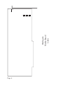
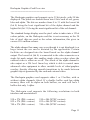
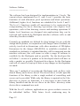
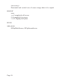
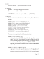
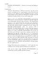
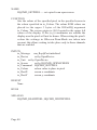
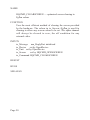
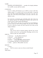
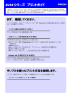
HARLEQUIN
The 32 bit Frame Buffer
User Manual
1991
COPYRIGHT
This manual is the Copyright (c) 1990 of
Keybonus Ltd. All Rights Reserved. This
document may not, in whole or in part, be
copied, photocopied, reproduced, translated,
or reduced to any electronic medium or
machine readable form, without prior written
consent, in writing, of Keybonus Ltd.
Marketed internationally by
Amiga Centre Scotland.
Harlequin House
Walkerburn
Peeblesshire
Scotland EH43 6AZ
Tel: 089 687 583
Fax: 089 687 456
TABLE OF CONTENTS
Introduction .........................................................
Registration, support and upgrades .......................
Installing The Harlequin Board ...........................
What it does ........................................................
Software Interface & Programmers guide ...........
General outline ...........................................
Overview ............................................
Software Outline ................................
Cardless software ...............................
Bug reporting .....................................
Interface Library ..................................................
Interface Device ..................................................
Product specification ...........................................
1
1
2
7
11 - 54
11 - 14
11
12
13
14
15 - 35
37 - 54
56 - 59
LIST OF FIGURES
Mother board (Links) ........................................
External connections .........................................
6
57
ACKNOWLEDGEMENTS
The Harlequin manual was produced using Professional Page V 2.0
on an Amiga 3000.
Keybonus would like to take this opportunity to thank the following:Jan Jones, Andrew Moss and Alan Tucker for their confidence
in bringing the original Harlequin Frame Buffer (a jumble of
wires connected to the parallel port of an Amiga 500) to Amiga
Centre Scotland. They worked enthusiastically at all times of
day and night to improve the specification and to implement it
on an Amiga 2000 internal card.
V.A. Elliott M.C. for his continuous interest in the project, for
his belief in it, and his help in creating the organisation to
successfully develop it.
BBDP for the quality and professionalism that they incorporated
in the design and manufacture, and for magnificent efforts to
enable the pre-production boards to be successfully
demonstrated at shows in London and Cologne.
David Grieve of Ekka Electronics for not only providing a
superb handsome design, but also for his willingness to discuss
at midnight the implementation of the latest ideas for revisions
to the specification.
Ian Ballantyne of Scope Picture Production, Glasgow, for his
help and advice in ensuring that the Harlequin fully meets the
requirements of IEEE 470-1 broadcast specification.
Various staff at CBM, for their help at various stages especially
on the software interface.
Mike Tinker who produced software to load images to the
Harlequin before he even had a board. He designed and
implemented the software interface for the Harlequin, which
software developers from all over the world have commented on
enthusiastically.
All staff at the Amiga Centre Scotland for their time and
patience.
This is by no means an exhaustive list of those we should thank,
as this would take several pages of the manual, please regard
this as a personal thanks to any one involved.
Lastly our sincere thanks to you for your purchase of the
Harlequin.
INTRODUCTION
Congratulations on the purchase of your new Harlequin Frame
Buffer. The Harlequin is a 32 bit Frame Buffer for the Amiga
computer, this allows in excess of 16.7 million colours to be
displayed on screen. So you can now see the advantage offered by
24 bit graphics software packages. You will notice this leaves an
extra 8 bits, which we call the Alpha channel. This can be used for
more sophisticated equipment to allow linear keying and is
discussed in greater detail in the ‘What it does’ chapter.
The Harlequin board has been designed to provide compatibility
with a range of additional accessories, including Genlocks, single
frame controllers, and other video equipment. The board is designed
for the Zorro II bus used in the Amiga range of computers, and has
been satisfactorily tested in most A2000 and A3000 versions.
The output from the Harlequin is totally independent from the
Amiga video, offering a range of resolutions in both interlace and
non interlace modes. This allows one or more boards to be
incorporated in an Amiga each driving a separate device. The
Amiga’s multi tasking allows different images to be output from
each Harlequin while retaining the original Amiga monitor output.
REGISTRATION
Keybonus treats the support for the Harlequin and other products it
produces very seriously. We are continually improving our existing
products and producing new products, and normally make these
improvements available in the form of product upgrades. It is
therefore imperative that you fill out and return the registration card
you received with this product. Failure to do so will mean we may
be unable to contact you regarding upgrades to the Harlequin.
Furthermore technical support will not be given to anyone who is
not in our registered user database. So please send in your
registration card.
Page 1
INSTALLING THE HARLEQUIN BOARD
WARNING
Some of the components on your Harlequin board and inside the
Amiga are sensitive to static electricity. When installing the
Harlequin board, it is imperative that you work in a static free
environment, always being careful to ground yourself against the
Amiga’s chassis before handling the Harlequin board. If you are
uncertain about working inside the Amiga, then ask your dealer to
install the board for you. A failure to take these precautions will
invalidate your warranty.
The installation of the Harlequin is a relatively simple operation. All
you need is a small phillips head screwdriver and a pair of steady
hands to install the board. The following steps outline the procedure
involved :
Software Installation
To install the Harlequin software onto a system disk from the floppy
disk provided :1. Boot the machine in the normal way
2. Insert the Harlequin disk and double click on the Harlequin disk
icon.
3. Double click on the install icon.
This will copy the library & device driver to your hard disk Libs:
and Devs: directories respectively.
NOTE: The above must be performed before huser can be run. To
run huser double click on it’s icon.
Page 2
Hardware installation
1. Ensure the Amiga is turned off, and disconnected from the
power supply, along with any peripherals attached to it.
2. Remove the Amiga’s case. This is secured by a number of
phillips head screws, and requires the use of the aforementioned
screwdriver. In the case of the Amiga 2000 and 1500 there are five
screws, two located on each side of the case near the bottom, and the
fifth is located in the center of the rear panel, near the top. (Be
careful to place the screws where they can not fall into the the open
computer.) Once loose the case should be slid forward, then lifted
off, being careful not to snag any wires in the process.
3. Having exposed the Amiga’s guts, be sure to ground yourself by
touching the exposed metal on the chassis. Locate a vacant Zorro II
slot. In the case of the Amiga 2000 and 1500 these are the five
parallel slots towards the front of the motherboard. Unscrew the
metal cover plate from behind the selected slot, and remove it,
saving the screws for use later.
4. Remove the Harlequin board from its packaging. If sync on
green is required the jumper at S6 should join the middle and sync
pins, if not required then the jumper should be moved to join the
middle pin and the pin towards the centre of the board. (see the
diagram at the end of this section).
Page 3
5. Align the board with the selected slot. There is a plastic card
guide at one end, and this should be used to correctly align the card
with the slot. Push the card gently but firmly home into the slot,
ensuring that the board does not contact any other boards in the
process (in some cases this may mean leaving a vacant slot adjacent
to the Harlequin board). Attach the mounting bracket using the
screws saved at the last step.
6. The Harlequin board is now installed in the Amiga, and you can
replace the case and resecure it with the original screws.
7.
Ensure the Amiga is turned off then reconnect the power supply.
8. Re boot your Amiga as normal. If the board is installed correctly
the computer will boot exactly as it did before installation.
9. Using the floppy disk provided, or a copy of it. Run the test
program ‘huser’. The program is mouse driven with large blue
selection buttons. Select :- screen format, Buffer 0, any resolution,
interlaced then System info. The program should report the details
of the Harlequin board installed, with the memory found displayed
in Megabytes.
10. This completes the installation of the Harlequin board in the
Amiga, however the board now needs to be connected to the outside
world. In most cases this will be a display monitor or piece of video
equipment.
Page 4
11. Power off the Amiga, prior to connecting any leads to the
Harlequin board.
12. Connect one end of the lead to the Video output from the
Harlequin board, and the other end to your display or video
equipment.
13. Power on the equipment, and re-boot the Amiga.
14. Using the floppy disk provided, or a copy of it. Run the test
program ‘huser’. The program is mouse driven with large blue
selection buttons. Select :- screen format, Buffer 0, any resolution,
interlaced, clear screen then Rectangles or lines. A simple test
pattern of rectangles or lines should be visable on the display.
The Harlequin board is now fully installed. For further information
on what it can achieve, read the chapter on ‘WHAT IT DOES’.
Page 5
S6
S5
IN
B
OUT
IN
G
OUT
IN
R
OUT
Page 6
S4
S3
Harlequin
Motherboard
Links
SYNC
WHAT IT DOES
Harlequin gives you a great image! If you care about your image,
whether its your image with customers or friends, or the image you
create in your Amiga, Harlequin will enhance it.
By giving you a choice of nearly 17 million colours for every pixel,
Harlequin faithfully delivers your image whether it comes from the
real world or from the limits of your own creative genius. By
whatever means you intend to let the world see the fruits of your
efforts, Harlequin’s output lets you choose stills or animation,
broadcast quality video, or photorealistic, high resolution monitor
display.
Loading images to Harlequin
If you are using an application package which has a standard
Harlequin driver then simply follow the instructions of your
application package and enjoy the Harlequin output.
If your image file is in one of the many formats supported by the
Rasterlink software delivered with your Harlequin then use Rasterlink
to load your image to Harlequin. Rasterlink may be used
independently from Harlequin to convert image files from one format
to another.
Taking images from Harlequin
Depending on how you wish to view your image, you will make use
of some or all of Harlequin’s outputs:RGB + Composite sync (1v pk-pk 75Ohms)
Digital key output
Alpha channel (1v pk-pk 75Ohms)
Genlock control lines
and Harlequin’s configuration modes:-
Page 7
Double buffering (3000 & 4000 only)
3 Resolutions
Interlaced/Non-interlaced
RGB + Composite Sync
The main outputs from Harlequin are the red, green and blue signals
which may be obtained individually with sync on green (switchable).
Inside Harlequin, 8 bits are used to define each of the red, green and
blue values for each pixel. In high res there are 910x576 pixels per
image (910x486 NTSC). For each of those pixels the colour
definitions use 24 bits leaving 8 bits for other effects.
Digital key output
One bit is connected to the video output as a simple bit mask to enable
overlays of external video on an on/off basis. The Harlequin output
is effectively stencilled on the external video.
Alpha channel - Linear keying
If simple on/off overlays are not enough for you then the Harlequin
gives you access to a full 8 bit Alpha channel which is output as a 256
level linear key, which can be used to control more advanced video
equipment. With this capability it is possible to produce stunning
superimpositions of text and graphics over live video.
Consider values 0 to 255 on the Alpha channel as representing how
transparent the Harlequin image will be when overlaid on the external
video. With value 0 only the Harlequin image is seen, while 255
gives wholly external video. Intermediate values give the appropriate
mixture. Used selectively, this allows smooth transitions at the edges
of computer text and graphics when overlaid on video.
Page 8
When used globally on all pixels it allows you to fade external video
to or from a specific colour, or cross fade between Harlequin graphics
and external video. The end result depends on your own creativity.
Genlockability
The Harlequin’s output has the synchronising signals required by
genlocking devices. To mix video signals it is necessary to
synchronise them. Harlequin’s broadcast quality output is ideal. If
your video equipment is prone to drift and you would like the ability
to trim the Harlequin’s output to match, then providing you have
purchased a model /T, you can. Please refer to appendix NN for
details.
Double buffering
On Harlequin 3000 and 4000 there are double buffers. This means
that one frame may be loading while the other is on display.
Switching between frames is accomplished by a software switch and
is a very effective means of producing a slide show or limited real
time animation. Animators can flick between two adjacent frames as
necessary.
Interlace/Non-Interlace
On a suitable monitor, Harlequin’s output is superb and rock steady in
non-interlace mode. When working with video it is necessary,
because of the video standards for T.V., to use Harlequin’s interlace
mode.
Page 9
Page 10
Harlequin Graphics Card Overview
================================
The Harlequin graphics card supports up to 32 bit pixels, with 24 bits
displayed. The pixels are broken down into 8 bits each of red, green,
blue and alpha. The bits are number from 0 to 31 with the lowest bit
(bit 0) being the least significant bit of the alpha channel and the
highest bit (bit 31) being the most significant bit of the red channel.
The standard Amiga display uses the pixel value to index into a 12 bit
colour palette, on the Harlequin card this is not necessary as the 24
bits of pixel data are used as the colour information, this gives in
excess of 16 million colours.
The alpha channel has many uses even though it is not displayed, to a
large extent the use can be dictated by the application. Certain
facilities are designed into the board based on the alpha channel
output. The lowest bit (bit 0) is connected to the video connector as a
single bit mask output, this enables simple video overlays where the
external video is either on or off. The whole of the alpha channel is
also output as a 256 level linear key which is able to control more
advanced video equipment to allow variable levels of video/graphics
overlay, thereby allowing smooth transitions to be made between
graphic objects generated by the card and external video.
The Harlequin graphics card supports either 1 or 2 buffers, with or
without alpha channels fitted. If a double buffer card has alpha
memory there will be alpha on both buffers, no card will have 2
buffers but only 1 alpha.
The Harlequin card supports the following resolutions in both
interlace and non-interlace:
910 x 576 (PAL version)
832 x 576 (PAL version)
740 x 576 (PAL version)
910 x 486 (NTSC version)
832 x 486 (NTSC version)
740 x 486 (NTSC version)
Page 11
Software Outline
===============
The software has been designed for implementation in 3 levels. The
current release implements level 1 only. Level 1 provides the basic
functions of card allocation, pixel operations and block operations.
Additional, higher level, functions are scheduled for levels 2 and 3.
The level 1 functions enable all operations to be constructed by
compounding the basic drawing operations into higher level
operations, such as line drawing, cursors and masking operations. If
higher level functions are designed into applications they can be
removed and replaced by Harlequin interface software calls as and
when they become available.
Currently no standards are defined for deep bitmaps for use with the
Amiga but Keybonus, in conjunction with Amiga Centre Scotland, are
actively involved in discussions with other members of GRAphics
Extensions for the Amiga (GRAFEXA) to establish a standard. As
standards are defined it is intended that they will be integrated into the
interface software, this will ensure as wide a range of software is
available for the Harlequin card as possible. For the developer this
will allow 1 version of a product to be developed which will have as
wide a market as possible. Registered developers for the Harlequin
card will of course be kept up to date as any changes or developments
are made.
There are 2 methods of accessing the Harlequin card, an Exec style
shared library and a device driver. The device driver is built upon the
functions of the library so that a single method of controlling card
access can be provided. While only the library is required in the Libs:
directory to access its functions, it is necessary to have both the
library installed and the device driver in the Devs: directory when
device driver commands are used.
With the Level 1 software, applications are given exclusive access to
the individual buffers. With future levels windowing may be
Page 12
implemented, this will have the effect of allowing different screen
sizes to be opened than are supported in hardware, ensure that the the
screen allocated by a call to HOpenScreen is adequate for the purpose
you have in mind. If it is essential that a full buffer is always allocated
(for example double buffered animation) set the EXCLUSIVE bit in
the HNewScreen. Type field before opening the screen. Remember
that the full palette is always available with the Harlequin card, even
when multiple windows are open, so that in the many occasions when
a custom screen was required with the normal Amiga display it is not
always necessary with the Harlequin.
When requesting screens by screen number please note that the lowest
screen number, zero, is the first buffer on the first card (looking from
the front of the Amiga this is the Harlequin card in the right most
slot). The next screen will be 1 which is the second buffer of the first
card, if fitted. Any second card fitted will always have the first buffer
numbered 2, even when the first card didn’t have a second buffer. The
interface software will support a virtually unlimited number of cards.
No calls should be made to any Harlequin function while Forbid or
Disable are active, except where indicated in the documentation, as a
deadlock could result. Deadlocks would be caused when task A has
use of the card but a Forbid by task B never allows task A to
complete, and therefore relinquish control of the card, leaving task B
waiting for control.
Cardless Software
=================
A version of the library is supplied that will work without a Harlequin
card fitted and simulate the actual operations available with the card.
The library is located in the libs directory on the developers disk and
called harlequin_cardless.library, it will be necessary to copy this file
to your assigned libs: directory and rename it to harlequin.library. The
Page 13
software simulates a double buffered PAL card with alpha channels
fitted.
When used with a standard A2000 and 68000 the library will operate
at approximately the same speed as an A2000 and Harlequin card
configuration. When used with an A2000 and accelerator card or an
A3000 the library will run faster than normal, this is because the
simulated writes will be to 32 bit memory at full processor speed. It is
unfortunately not possible to give timings for how much of a speed
increase this will provide as it very much depends on the operation.
The only way to obtain accurate timings is to test with the Harlequin
card fitted!
Bug Reports
===========
This software is pre-release and we therefore request detailed bug
reports. While this level of the software has a fairly limited set of
functions there are many variations possible with many of the
functions, some may have slipped through early testing (the
HClipBlockScreen has 256 possible combinations of source/dest
DrawModes!).
The interface software is designed to enable application programmers
to write simpler drawing functions and to simplify porting existing
applications to the Harlequin card, many options were left open so
that developers could make requests for functions that could be
included, either before public release or in higher levels of the
interface. If there is something that you would find indispensable then
please pass your comments onto Amiga Centre Scotland.
Page 14
NAME
HOpenScreen — allocate and set format of a screen
SYNOPSIS
HScreen = HOpenScreen(HNewScreen)
D0
A0
struct HScreen *HOpenScreen(struct HNewScreen *)
FUNCTION
Allocates and initialises a HScreen structure, sets the screen
format according to the requirements in the HNewScreen
structure. If the HNewScreen.Type HDISPLAY flag is set the
screen display will be turned on, although the display may still
be hidden if another buffer is in use on the same card.
Before a call to the HOpenScreen function the HNewScreen
structure must be initialised with the required screen dimensions
and any Flags necessary. The HNewScreen structure is not
required after the call and, unless screen conversions are to take
place, can be discarded.
With the Level 1 library, if the screen requested is already open
then the HOpenScreen function will fail. Ensure all
HOpenScreen calls are paired with a HCloseScreen call to
ensure that the screen is freed for use by other applications.
To open a double buffered display use 2 calls to HOpenScreen,
the screens on the same card will have consecutive numbers
with the first numbered even and the second odd, eg. 0/1, 2/3.
Setting the HDOUBLEBUFFER flag in HNewScreen.Type will
ensure that a screen is only allocated if there is a second buffer
available on the same card, the HDOUBLEBUFFER flag must
be cleared before attempting to open the second buffer. To open
the second, matching, buffer use the HScreen.ScreenNumber
from the HScreen returned by the first HOpenScreen call with
Page 15
the lower bit changed. Provided that the HDISPLAY bit is not
set in either of the HNewScreen structures the HOpenScreen call
can be surrounded with a Forbid/Permit pair.
Setting HNewScreen.ScreenNumber to -1 will cause the first
available screen with the required attributes to be allocated.
Calls can be made to HGetScreenInfo to establish the screens
available and their formats.
The screen is not cleared when opened, to open a screen with the
display on and cleared use the following sequence of function
calls:
HOpenScreen - with HNewScreen.Type HDISPLAY bit
clear
HClearScreen
HScreenFunction - with mask = SCREEN_ON
Unless the requested type was HBORDERLESS, future Levels
of the library may draw a border around the screen (to
implement windows), the borders will be drawn outside the
allocated screen area so that the pixel at location (0,0) will be
the first pixel in the drawing area upper left corner, not in the
border.
INPUTS
HNewscreen
Pointer to HnewScreen structure.
RESULT
HScreen
Pointer to HScreen structure on success, else zero
BUGS
SEE ALSO
HcloseScreen, HGetScreenInfo
Page 16
NAME
HCloseScreen — close a Harlequin screen previously opened by
a call to HOpenScreen
SYNOPSIS
HCloseScreen(screen)
A0
void HCloseScreen(struct HScreen *)
FUNCTION
This function closes a screen previously opened with a call to
HOpenScreen. The HScreen structure allocated by the call to
HOpenScreen will be freed by the call.
If another screen is open on the card it will be brought to the
front.
INPUTS
screen
Pointer to HScreen structure allocated by HOpenScreen
RESULT
None
BUGS
SEE ALSO
HOpenScreen
Page 17
NAME
HSetPixel — set a pixel in an open screen
SYNOPSIS
HSetPixel(screen, colour, x, y)
A0
D0 D1 D2
void HSetPixel (struct HScreen *,ULONG,SHORT,SHORT)
FUNCTION
Sets the colour of a pixel on screen. The colour RGB values are
placed in the upper 3 bytes of the function argument colour and
the alpha in the lower byte (when alpha is being used). The
screen origin is (0,0) located in the upper left corner of the
display.
If the (x,y) coordinates are outside the display area the pixel will
not be drawn.
When setting the pixel colour the settings in
HScreen.DrawMode are taken into account, this allows writing
to take place only to those channels that are enabled.
INPUTS
screen
Pointer to an open HScreen struct
colour
Colour value to place in pixel
(x.y)
Point within the screen that the pixel is to be written
RESULT
None
BUGS
SEE ALSO
HReadPixel, HWritePixel
Page 18
NAME
HReadPixel — read a pixel colour from an open screen
SYNOPSIS
colour = HReadPixel (screen, x , y)
D0
A0 D0 D1
ULONG HReadPixel(struct HScreen *,SHORT,SHORT)
FUNCTION
Reads the colour of the specified pixel in the specified screen.
The RGBA value for the pixel is placed in the return value
colour. No account is taken of HScreen.DrawMode so that the
full 32 bit pixel value is returned. The screen origin is 0,0
located in the upper left corner of the display.
No check is made for out of bounds (x,y) values, an out of
bounds read will return an unspecified colour.
INPUTS
screen
Pointer to open HScreen structure
(x,y)
Point within the screen that the colour is to be read from
RESULT
colour
RGBA value from screen x,y location with RGB values in
upper 3 bytes and alpha in lower byte
BUGS
SEE ALSO
HSetPixel, HWritePixel
Page 19
NAME
HWritePixel — writes the colour from HScreen.FgPen into the
screen
SYNOPSIS
HWritePixel (screen, x, y)
A0
D0 D1
void HWritePixel(struct HScreen *,SHORT,SHORT)
FUNCTION
Writes the colour from HScreen.FgPen to the pixel located at
(x,y) in the specified screen. The screen origin is (0,0) located in
the upper left corner of the display.
If the (x,y) coordinates are outside the display area the pixel will
not be drawn.
When setting the pixel colour the settings in
HScreen.DrawMode are taken into account, this allows writing
to take place only to those channels that are enabled.
INPUTS
screen
Pointer to open HScreen structure
(x,y)
Point within the screen that the FgPen is to be written
RESULT
None
BUGS
SEE ALSO
HSetPixel, HReadPixel
Page 20
NAME
HClipBlockScreen — copies image data from an ImageBlock
structure to the screen with clipping
SYNOPSIS
error = HClipBlockScreen(block, sourcex, sourcey, screen,
D0
A0 D0
D1 A1
destx, desty, sizex, sizey)
D2 D3
D4
D5
LONG HClipBlockScreen(struct ImageBlock *, SHORT,
SHORT, struct HScreen *, SHORT, SHORT,SHORT,SHORT)
FUNCTION
Copies a rectangle of image data from a source ImageBlock
located in Amiga main memory to the previously opened screen.
Clipping will take place should the source image data not fit
totally within the screen area.
The ImageBlock.Flags will be considered when the copy is
performed, thus allowing packed data or seperate RGB channels
to be used. When copying the pixel, the settings in
HScreen.DrawMode are taken into account, this allows writing
to take place only to those channels that are enabled.
No account is taken of the source ImageBlock size when
clipping, if the image data is smaller than the size of the
rectangle specified in the function parameters, random Amiga
main memory may be written to the display.
INPUTS
block
Pointer to ImageBlock structure containing image data to copy
to screen
(sourcex,sourcey)
Upper left corner location from which to start copy
Page 21
screen
Pointer to open HScreen structure for destination
(destx,desty)
Upper left corner location to which the image data will start to
be copied
(sizex,sizey)
Horizontal and vertical size of source image data to be copied
RESULT
error
-ve if completely off screen
0 if completely on screen
+ve if clipping took place
BUGS
SEE ALSO
HClipScreenBlock, HClipScreenScreen
Page 22
NAME
HClipScreenBlock — copies image data from a screen to a
previously allocated ImageBlock with clipping
SYNOPSIS
error = HClipScreenBlock(screen, sourcex, sourcey, block,
D0
A0 D0
D1 A1
destx, desty, sizex, sizey)
D2 D3
D4
D5
LONG HClipScreenBlock(struct HScreen *, SHORT, SHORT
struct ImageBlock *, SHORT,SHORT,SHORT,SHORT)
FUNCTION
Copies a rectangle of image data from a source screen located in
display memory to a previously allocated ImageBlock structure
with the image data memory allocated. Clipping will take place
should the source image data not fit totally within the
ImageBlock area.
The ImageBlock.Flags will be considered when the copy is
performed, thus allowing simple packing of the image data or
separation of the RGB values to take place in Amiga main
memory.
INPUTS
screen
Pointer to open HScreen structure for source
(sourcex,sourcey)
Upper left corner location from which to start copy
block
Pointer to ImageData structure to which screen data will be
copied
(destx,desty)
Upper left corner location to which the image data will start to
be copied
Page 23
(sizex,sizey)
Horizontal and vertical size of source image data to be copied
RESULT
error
-ve if completely off screen
0 if completely on screen
+ve if clipping took place
BUGS
SEE ALSO
HClipBlockScreen, HClipScreenScreen
Page 24
NAME
HClipScreenScreen — copies screen image data to another
screen or on the same screen with clipping
SYNOPSIS
error - HClipScreenScreen(sourcescreen, sourcex, sourcey,
D0
A0
D0
D1
destscreen, destx, desty, sizex, sizey)
A1
D2
D3
D4
D5
LONG HClipScreenScreen(struct HScreen *, SHORT, SHORT,
struct HScreen *, SHORT, SHORT, SHORT, SHORT)
FUNCTION
Copies a rectangle of image data from a source screen to a
destination screen, the source and destination screen pointers
may point to the same screen to allow image data to be copied
around screen. Clipping of both the source and destination
screen image data will take place should the source image data
not be totally within the screen areas.
Conversion will take place between the source screen image
data and the destination screen image data if the formats are
different.
When image data is being copied within the same screen, the
start point for the copy will be selected so as to prevent
overwritting of the source data by the destination write.
When setting the destination pixel the settings in
HScreen.Draw Mode are taken into account, this allows writing
to take place only to those channels that are enabled.
INPUTS
sourcescreen
Pointer to HScreen structure from which image data is to be
Page 25
copied
(sourcex,sourcey)
Upper left corner location of rectangle to copy
destscreen
Pointer to HScreen structure to which image data is to be
copied, may be same as sourcescreen
(destx,desty)
Upper left corner location of rectangle to copy too
(sizex,sizey)
Horizontal and vertical size of source image data to be copied
RESULT
error
-ve if completely off screen
0 if completely on screen
+ve if clipping took place
BUGS
SEE ALSO
HClipBlockScreen, HClipScreenBlock
Page 26
NAME
HScreenFunction — perform function on screen
SYNOPSIS
newmask = HScreenFunction(screen,mask)
D0
A0
D0
USHORT HScreenFunction(struct HScreen *,USHORT)
FUNCTION
Carries out various functions on the screen, these functions
include:
SCREEN_ON - turn screen RGB display on
SCREEN_OFF - turn screen RGB display off
SCREEN_FRONT - move screen to front
SCREEN_BACK - move screen to back
GENLOCK_ON - if present, turn genlock on
GENLOCK_OFF - turn genlock off
ALPHA_ON - turn screen alpha output on
ALPHA_OFF - turn screen alpha output off
The mask values perform the following functions:
SCREEN_ON, SCREEN_OFF
Attempt to turn the RGB output for the specified screen
either on or off. The function will fail if HEXCLUSIVE
access was not granted when the screen was opened (Level
1 software will always be granted HEXCLUSIVE access
but this may change in future levels), check the newmask
returned.
SCREEN_FRONT, SCREEN_BACK
Attempt to move the specified screen to either the front of
all others or behind all others. The function will fail if the
no other screen is open or if HEXCLUSIVE access has not
Page 27
been granted, check the newmask returned.
If the screen switch will be successful the function will not
return until the screens have been switched. When used for
animation, this will ensure that any future writes to the
back screen are not displayed.
GENLOCK_ON, GENLOCK_OFF
If fitted this mask will turn the genlock either on or off.
The function will fail if an attempt is made to turn on a
genlock when one is not fitted. If the genlock is already in
the requested state the operation will succeed.
ALPHA_ON, ALPHA_OFF
Attempt to turn the alpha output for the specified screen
either on or off. The function will fail if (in later levels of
the library only) any other screen is open in the same
buffer and has requested an alpha channel.
Set bits in the mask are processed from least significant to
most significant. If it is neccesary for a group of operations
to be carried out in a different order then multiply calls to
the function will be required.
INPUTS
screen
Pointer to HScreen structure for an open screen
mask
Mask value of functions requested
RESULT
newmask
Returns a mask value with bits set for the currently true
conditions. To find the current settings for the screen call
the function with mask = 0, this will not cause any changes
to be made to the current mask settings but will return the
Page 28
current mask.
BUGS
SEE ALSO
Page 29
NAME
HClearScreen — optimised screen clearing to FgPen colour
SYNOPSIS
HClearScreen(screen)
A0
void HClearScreen(struct HScreen *)
FUNCTION
Uses the most efficient method of clearing the screen provided
by the hardware. The colour in HScreen.FgPen is used for
clearing to allow any screen colour to be set. The alpha channel
will always be cleared to zero, the off condition for any external
video.
INPUTS
screen
Pointer to previously opened HScreen structure
RESULT
None
BUGS
SEE ALSO
Page 30
NAME
HConvertScreen — changes mode/resolution of open screen
SYNOPSIS
error = HConvertScreen(screen,newscreen, flags)
D0
A0 A1
D0
LONG HConvertScreen(struct HScreen *,struct HNewScreen *,
UBYTE)
FUNCTION
Attempts to convert the screen format to that specified in
newscreen.
When the screen conversion will reduce the screen width, it is
necessary to set the HNewScreen.ConvertX value to the x
location on the current screen that will become the left edge of
the converted screen.
When the screen conversion will increase the screen width, it is
necessary to set the HNewScreen.ConvertX value to the x
location on the converted screen that will become the left edge
of the current screen image.
The parameter, flags, is used to control the display during
conversion, the screen can be either turned off or left on view. It
must be remembered that screen conversion will corrupt the
display during the conversion. A flag can also be set which
causes no conversion of the image, this is primarily used when
the screen is known to be clear and will therefore not be
corrupted.
Generally conversion will only succeed if HEXCLUSIVE
access has been granted to the screen, this is the only means of
access to the Level 1 library but this may change with future
levels of the library.
Page 31
Upto 0.5Mb of memory is currently required during screen
conversion, if the memory is not available the function will fail.
INPUTS
screen
Pointer to currently open screen
newscreen
pointer to HNewScreen structure initialised to the required
parameters.
flags
Options while conversion takes place
RESULT
error
Non zero for success, the screen structure will contain the
new screen parameters, else zero
BUGS
SEE ALSO
Page 32
NAME
HGetScreenInfo — searches display database for available
screens and their modes
SYNOPSIS
error = HGetScreenInfo(screeninfo)
D0
A0
LONG HGetScreenInfo(struct HScreenInfo *)
FUNCTION
Used to obtain information on available screens and their
display modes. If a search for all screens and modes is required
clear the HScreenInfo.MatchMode field before the first call.
Each call will fill the HScreenInfo structure with the next
database entry.
To search for a particular type of display place the values for the
required type in the HScreenInfo structure and specify the
search criteria in HScreenInfo.MatchMode.
If the HScreenInfo structure has already been used during a
previous series of calls to HScreenInfo clear the Info_ID fields
to zero so that the search will start from the first entry in the
display database.
NOTE:
The screens will be returned starting with the first screen
buffer on the first card installed, finishing with the last
buffer on the last card installed.
INPUTS
screeninfo
Pointer to HScreenInfo structure
Page 33
RESULT
error
Returns -1 when no match found, else zero
BUGS
SEE ALSO
Page 34
NAME
HRectFill — fills a rectangle with FgPen colour
SYNOPSIS
error = HRectFill(screen, xmin, ymin, xmax, ymax)
D0
A0
D0
D1 D2
D3
LONG HRectFill(struct HScreen *, SHORT, SHORT, SHORT,
SHORT)
FUNCTION
Fills a rectangle on the specified screen with the colour in
screen->FgPen.
Clipping will take place should the rectangle not fit totally
within the destination screen area.
When setting the destination pixel the settings in
HScreen.DrawMode are taken into account, this allows writing
to take place only to those channels that are enabled.
INPUTS
screen
Pointer to HScreen structure
(xmin,ymin)
Upper left corner of rectangle to be filled
(xmax,ymax)
Lower right corner of rectangle to be filled
RESULT
error
-ve if completely off screen
0 if completely on screen
+ve if clipping took place
BUGS
SEE ALSO
Page 35
Page 36
NAME
HQCMD_OPENSCREEN — allocate, set format and display a
screen
FUNCTION
Allocates and initialises a HScreen structure, sets the screen
format according to the requirements in the HNewScreen
structure. If the HNewScreen.Type HDISPLAY flag is set the
screen display will be turned on, although the display may still
be hidden if another buffer is in use on the same card.
Before a call to the HQCMD_OPENSCREEN command the
HNewScreen structure must be initialised with the required
screen dimensions and any Flags necessary. The HNewScreen
structure is not required after the call and can be discarded.
With the Level 1 device, if the screen requested is already open
the HQCMD_OPENSCREEN command will fail. Ensure all
HQCMD_OPENSCREEN calls are paired with a
HQCMD_CLOSESCREEN calls to ensure that the screen is
freed for use by other applications. To open a double buffered
display use 2 calls to HQCMD_OPENSCREEN, the screens on
the same card will have consecutive numbers with the first
numbered even and the second odd, eg. 0/1, 2/3. Setting the
HDOUBLEBUFFER flag in HNewScreen.Type will ensure that
a screen is only allocated if there is a second buffer available on
the same card, the HDOUBLEBUFFER flag must be cleared
before attempting to open the second buffer. To open the
second, matching, buffer use the HScreen.ScreenNumber
returned by the first HQCMD_OPENSCREEN call and change
the least significant bit.
Setting HNewScreen.ScreenNumber to -1 will cause the first
available screen with the required attributes to be allocated.
Calls can be made using HQCMD_GETSCREENINFO to
establish the screens available and their formats.
Page 37
To open a screen with the display on and cleared use the
following sequence of command calls
HQCMD_OPENSCREEN - with Type HDISPLAY bit
clear
HQCMD.CLEARSCREEN
HQCMD_SCREENFUNCTION - with mask =
SCREEN_ON
Unless the requested type was HBORDERLESS, future levels
of the library may draw a border around the screen (to
implement windows), the borders will be drawn outside the
allocated screen area so that the pixel at location (0,0) will be
the first pixel in the drawing area upper left corner, not in the
border.
IO REQUEST
io_Message mn_ReplyPort initialised
io_Device
set by OpenDevice
io_Unit
set by OpenDevice
io_Command HQCMD_OPENSCREEN
io_Data
pointer to HNewScreen structure
RESULT
io_error
If the command succeeded io_Error will be null. If the
command
failed io_Error will be non-zero.
io_Screen
Pointer to HScreen structure on success
BUGS
SEE ALSO
HQCMD_CLOSESCREEN, HQCMD_GETSCREENINFO
Page 38
NAME
HQCMD_CLOSESCREEN — close a Harlequin screen
previously opened by the HQCMD_OPENSCREEN command
FUNCTION
This command closes a screen previously opened by the
HQCMD_OPENSCREEN command. The HScreen structure
allocated by the HQCMD_OPENSCREEN command will be
freed by the call and the display will be turned off.
If another screen is open on the card it will be brought to the
front.
INPUTS
io_Message mn_ReplyPort initialised
io_Device
set by OpenDevice
io_Unit set by OpenDevice
io_Command HQCMD_CLOSESCREEN
RESULT
None
BUGS
SEE ALSO
HQCMD_OPENSCREEN
Page 39
NAME
HQCMD_SETPIXEL — set a pixel in an open screen
FUNCTION
Sets the colour of the specified pixel in the specified screen to
the colour specified in io_Colour. The colour RGB values are
placed in the upper 3 bytes of the IOExtHQ argument
io_Colour. The screen origin is (0,0) located in the upper left
corner of the display. If the (x,y) coordinates are outside the
display area the pixel will not be drawn. When setting the pixel t
colour the settings in HScreen.DrawMode are taken into
account, this allows writing to take place only to those channels
that are enabled.
INPUTS
io_Message
mn_ReplyPort initialised
io_Device
set by OpenDevice
io_Unit set by OpenDevice
io_Screen
set by HQCMD_OPENSCREEN
io_Comrnand HQCMD_SETPIXEL
io_Colour
colour value to place in pixel
io_DestX
screen x coordinate
io_DestY
screen y coordinate
RESULT
None
BUGS
SEE ALSO
HQCMD_READPIXEL, HQCMD_WRITEPIXEL
Page 40
NAME
HQCMD_READPIXEL — read a pixel colour from an open
screen
FUNCTION
Reads the colour of the specified pixel from the screen. The
colour RGBA value is placed in io_Colour. The screen origin
is (0,0) located in the upper left corner of the display. No
account is taken of HScreen.DrawMode so that the full 32 bit
pixel value is returned. No check is made for out of bounds
(x,y) values, an out of bounds read will return an unspecified
colour.
INPUTS
io_Message
mn_ReplyPort initialised
io_Device
set by OpenDevice
io_Unit set by OpenScreen
io_Screen
set by HQCMD_OPENSCREEN
io_Command HQCMD_SETPIXEL
io_DestX
screen x coordinate
io_DestY
screen y coordinate
RESULT
io_Colour
Colour value from screen x,y location with RGB values in
upper 3 bytes and alpha in lower byte
BUGS
SEE ALSO
HQCMD_SETPIXEL, HQCMD_WRITEPIXEL
Page 41
NAME
HQCMD_WRITEPIXEL — writes the colour from
io_Screen->FgPen into the screen
FUNCTION
Writes the colour from io_Screen->FgPen to the pixel located at
(io_destX, io_DestY) in the specified screen. The screen origin
is (0,0) located in the upper left corner of the display. If the
(x,y) coordinates are outside the display area the pixel will not
be drawn. When setting the pixel colour the settings in
HScreen.DrawMode are taken into account, this allows writing
to take place only to those channels that are enabled.
INPUTS
io_Message
mn_ReplyPort initialised
io_Device
set by OpenDevice
io_Unit set by OpenDevice
io_Screen
set by HOpenScreen
io_Command HQCMD_WRITEPIXEL
io_DestX
screen x coordinate
io_DestY
screen y coordinate
RESULT
None
BUGS
SEE ALSO
HQCMD_SETPIXEL, HQCMD_READPIXEL
Page 42
NAME
HQCMD_CLIPBLOCKSCREEN — copies image data from an
ImageBlock structure to the screen with clipping
FUNCTION
Copies a rectangle of image data from a source ImageBlock
located in Amiga main memory to the previously opened screen.
Clipping will take place should the source image data not fit
totally within the screen area. The ImageBlock.Flags will be
considered when the copy is performed, thus allowing simple
packing of the image data or seperate RGB values to be placed
on the screen. When copying the pixel the settings in
HScreen.DrawMode are taken into account, this allows writing
to take place only to those channels that are enabled. No
account is taken of the source ImageBlock size when clipping,
if the image data is smaller than the size of the rectangle
specified in the function parameters, random Amiga main
memory may be written to the display.
INPUTS
io_Message
mn_ReplyPort initialised
io_Device
set by OpenDevice
io_Unit set by OpenDevice
io_Screen
set by HQCMD_OPENSCREEN
io.Command HQCMD_CLIPBLOCKSCREEN
io_Data source ImageBlock pointer
io_DestX
destination screen start x
io_DestY
destination screen start y
io_SourceX
source ImageBlock start x
io_SourceY
source ImageBlock start y
io_SizeX
block width
io_SizeY
block height
RESULT
io_Error
-ve if completely off screen
Page 43
0 if completely on screen
+ve if clipping took place
BUGS
SEE ALSO
HQCMD_CLIPSCREENBLOCK,
HQCMD_CLIPSCREENSCREEN
Page 44
NAME
HQCMD_CLIPSCREENBLOCK — copies image data from a
screen to a previously allocated ImageBlock with clipping
FUNCTION
Copies a rectangle of image data from a source screen located in
display memory to a previously allocated ImageBlock structure
with the image data memory allocated. Clipping will take place
should the source image data not fit totally within the
ImageBlock area. The ImageBlock.Flags will be considered
when the copy is performed, thus allowing simple packing of
the image data or seperation of the RGB values to take place in
Amiga main memory.
INPUTS
io_Message
mn_ReplyPort initialised
io_Device
set by OpenDevice
io_Unit set by OpenDevice
io_Screen
set by HQCMD_OPENSCREEN
io_Command HQCMD_CLIPSCREENBLOCK
io_Data destination ImageBlock pointer
io_DestX
destination ImageBlock start x
io_DestY
destination ImageBlock start y
io_SourceX
source screen start x
io_SourceY
source screen start y
io_SizeX
block width
io_SizeY
block height
RESULT
io_Error
-ve if completely off screen
0 if completely on screen
+ve if clipping look place
BUGS
SEE ALSO
HQCMD_CLIPBLOCKSCREEN,
HQCMD_CLIPSCREENSCREEN
Page 45
NAME
HQCMD_CLIPSCREENSCREEN — copies screen image data
to another screen or on same screen with clipping
FUNCTION
Copies a rectangle of image data from a source screen to the
IOExtHQ screen, the source and destination screen may be the
same screen to allow image data to be copied around screen.
Clipping of both the source and destination screen image data
will take place should the source image data not be totally
within the screen areas.
Conversion will take place between the source image data and
the destination image data if the formats are different.
When image data is being copied within the same screen, the
start point for the copy will be selected so as to prevent
overwritting of the source data by the destination write.
When setting the destination pixel the settings in
HScreen.DrawMode are taken into account, this allows writing
to take place only to those channels that are enabled.
INPUTS
io_Message mn_ReplyPort initialised
io_Device
set by OpenDevice
io_Unit set by OpenDevice
io_Screen
set by HQCMD_OPENSCREEN
io_Command HQCMD_CLIPSCREENSCREEN
io_Data source HScreen pointer
io_DestX
destination screen start x
io_DestY
destination screen start y
io_SourceX source screen start x
io_SourceY
source screen start y
io_SizeX
block width
io_SizeY
block height
RESULT
io_Error
Page 46
-ve if completely off screen
0 if completely on screen
+ve if clipping took place
BUGS
SEE ALSO
HQCMD_CLIPBLOCKSCREEN,
HQCMD_CLIPSCREENBLOCK
Page 47
NAME
HQCMD_SCREENFUNCTION — perform function on screen
FUNCTION
Carries out various functions on the screen, these functions
include:
SCREEN_ON - turn screen RGB display on
SCREEN_OFF - turn screen RGB display off
SCREEN_FRONT - move screen to front
SCREEN_BACK - move screen to back
GENLOCK_ON - if present, turn genlock on
GENLOCK_OFF - turn genlock off
ALPHA_ON - turn screen alpha output on
ALPHA_OFF - turn screen alpha output off
The mask values perform the following functions:
SCREEN_ON, SCREEN_OFF
Attempt to turn the RGB output for the specified screen
either on or off. The command will fail if HEXCLUSIVE
access was not granted when the screen was opened (Level
1 software will always be granted HEXCLUSIVE access
but this may change in future levels), check the io_Mask
return.
SCREEN_FRONT, SCREEN_BACK
Attempt to move the specified screen to either the front of
all others or behind all others. The command will fail if
the display is not double buffered or if HEXCLUSIVE
access has not been granted, check the io_Mask return.
If the screen switch will be successful the function will not
return until the screens have been switched. When used
for animation, this will ensure that any future writes to the
back screen are not displayed.
Page 48
GENLOCK_ON, GENLOCK_OFF
If fitted this mask will turn the genlock either on or off.
The command will fail if an attempt is made to turn on a
genlock when one is not fitted. If the genlock is already
in the requested state the operation will succeed
ALPHA_ON, ALPHA_OFF
Attempt to turn the alpha output for the specified screen
either on or off. The ALPHA_ON command will fail if
no alpha channel is fitted.
Set bits in the mask are processed from least significant to most
significant. If it is necessary for a group of operations to be
carried out in a different order then multiply calls to the function
will be required.
INPUTS
io_Message
mn_ReplyPort initialised
io_Device
set by OpenDevice
io_Unit set by OpenDevice
io_Screen
set by HQCMD_OPENSCREEN
io_Command HQCMD_SCREENFUNCTION
io_Mask mask value for functions requested
RESULT
io_Mask
Returns an io_Mask value with bits set for the currently
true
conditions. To find the current settings for the screen call
the
function with mask = 0, this will not cause any changes to
be
made to the current mask settings but will return the
current mask.
BUGS
SEE ALSO
Page 49
NAME
HQCMD_CLEARSCREEN — optimised screen clearing to
FgPen colour
FUNCTION
Uses the most efficient method of clearing the screen provided
by the hardware. The colour in io_Screen->FgPen is used for
clearing to allow any screen colour to be set. The alpha channel
will always be cleared to zero, the off condition for any
external video.
INPUTS
io_Message mn_ReplyPort initialised
io_Device
set by OpenDevice
io_Unit set by OpenDevice
io_Screen
set by HQCMD_OPENSCREEN
io_Command HQCMD_CLEARSCREEN
RESULT
BUGS
SEE ALSO
Page 50
NAME
HQCMD_CONVERTSCREEN — changes mode/resolution of
open screen
FUNCTION
Attempts to convert the screen format to that specified in
io_Data->HNewScreen.
When the screen conversion will reduce the screen width, it is
necessary to set the HNewScreen.ConvertX value to the x
location on the current screen that will become the left edge of
the converted screen.
When the screen conversion will increase the screen width, it is
necessary to set the HNewScreen.ConvertX value to the x
location on the converted screen that will become the left edge
of the current screen image.
The io_Mask is used to control the display during conversion,
the screen can be either turned off or left on view. It must be
remembered that screen conversion will corrupt the display
while the conversion takes place. An io_Mask bit can also be
set which causes no conversion of the image, this is primarily
used when the screen is known to be clear and will therefore not
be corrupted. Generally conversion will only succeed if
HEXCLUSIVE access has been granted to the screen, this is the
only means of access to the Level 1 device but this may change
with future levels of the device. Up to 0.5Mb of memory is
currently required during screen conversion, if the memory is
not available the command will fail.
INPUTS
io_Message
mn_ReplyPort initialised
io_Device
set by OpenDevice
io_Unit set by OpenDevice
io_Screen
set by HQCMD_OPENSCREEN
io_Command HQCMD_CONVERTSCREEN
Page 51
io_Data pointer to HNewScreen structure
io_Mask conversion mask/flags
RESULT
io_Error
Null for success, the screen structure will contain the new
screen parameters, else non zero
BUGS
SEE ALSO
Page 52
NAME
HQCMD_GETSCREENINFO — searches the display database
for available screens and their modes
FUNCTION
Used to obtain information on available screens and their
display modes. If a search for all screens and modes is required
clear the HScreenInfo.MatchMode field before the first call.
Each call will fill the HScreenInfo structure with the next
database entry.
To search for a particular type of display place the values for
the required type in the HScreenInfo structure and specify the
search criteria in HScreenInfo.MatchMode.
If the HScreenInfo structure has already been used during a
previous series of calls to HScreenInfo clear the Info_ID fields
to zero so that the search will start from the first entry in the
display database.
NOTE:
The screens will be returned starting with the first screen
buffer on the first card installed, finishing with the last
buffer on the last card installed.
INPUTS
io_Message
mn_ReplyPort initialised
io_Device
set by OpenDevice
io_Unit set by OpenDevice
io_Screen
set by HQCMD_OPENSCREEN
io_Command HQCMD_GETSCREENINFO
io_Data pointer to HScreenInfo structure
RESULT
io_Error
Null for success, non zero when no match found
BUGS
SEE ALSO
Page 53
NAME
HQCMD_RECTFILL — fills a rectangle with FgPen colour
FUNCTION
Fills a rectangle on the screen with the colour in
io_Screen->FgPen. Clipping will take place should the rectangle
not fit totally within the destination screen area.
When setting the destination pixel the settings in
HScreen.DrawMode are taken into account, this allows writing
to take place only to those channels that are enabled.
INPUTS
io_Message
mn_ReplyPort initialised
io_Device
set by OpenDevice
io_Unit set by OpenDevice
io_Screen
set by HQCMD_OPENSCREEN
io_Command HQCMD_RECTFILL
io_DestX
left edge of area to fill
io_DestY
top edge of area to fill
io_SizeX
right edge of area to fill
io_SizeY
bottom edge of area to fill
RESULT
io_Error
-ve if completely off screen
0 if completely on screen
+ve if clipping took place
BUGS
SEE ALSO
Page 54
Page 55
PRODUCT SPECIFICATION
Harlequin Memory
Description
Board
1500 1.5Mb
Basic single buffered board
2000
2Mb
Single buffer board with Alpha Channel
3000
3Mb
Double buffered board without Alpha Channel
4000
4Mb
Double buffered board with Alpha Channel
There are two versions of the board reflecting the two TV standards,
namely PAL and NTSC
PAL
740 x 576
832 x 576
910 x 576
NTSC
740 x 486
832 x 486
910 x 486
Vertical Frequency
50 Hz
60 Hz
Horizontal Frequency
Interlaced
15.625 KHz
Non-interlaced
31.25 KHz
Page 56
15.734 KHz
31.5 KHz
EXTERNAL CONNECTIONS
There are two 15 pin sockets on the board one for the video output
and the other for the genlock interface.
The video output comprises a 15 pin D type female connector with
the following pin assignments :
PIN
DESCRIPTION
1
Mixed Blanking TTL levels
2
Mixed Syncs TTL levels
3
Field (Vertical) Syncs TTL levels
4
Line (Horizontal) Syncs TTL levels
5
Video Red
1v pk-pk into 75 ohms
6
Video Green
1v pk-pk into 75 ohms
7
Video Blue
8
15
Genlock
1
9
1
9
1v pk-pk into 75 ohms
Video
8
Video Alpha 1v pk-pk into 75 ohms
9
Digital Key
10
+5 Volts
11
Digital Ground
12
Analogue Ground
13
Analogue Ground
14
Analogue Ground
15
Analogue Ground
8
15
Page 57
The Genlock interface comprises a 15 pin D type male connector
with the following pin assignments :
PIN
1
2
3
4
5
6
7
8
9
10
11
12
13
14
15
DESCRIPTION
VMODE0
GROUND
VMODE1
Ground
/GPRES
Ground
/LSYNC
Ground
/FSYNC
Ground
/FRST
Ground
Ground
Ground
GLCLK
VMODE0, VMODE1 -Video mode select output
These binary coded bits enable the genlock to select its VCO
centre frequency for each video mode. The nominal value is
different for each horizontal resolution and between PAL and
NTSC. The table below summarises the required values. The
column marked ratio indicates the multiplying factor required
to generate the nominal master frequency from the nominal
line rate (PAL = 15,625Hz, NTSC = 15,734.264Hz).
Page 58
/GPRES Genlock present input
This pin is pulled to 5V through a 10k resistor on the
Harlequin card. The genlock should ground this pin so that the
Harlequin knows when the genlock is connected.
/LSYNC Line Synchronisation output
This pin carries ‘pure’ line sync pulses, that is, a 4.7us pulse
every 64us (PAL) or 63.5555us (NTSC), the pulse train has no
equalising pulses or other artifacts of field synchronisation.
The signal is at TTL levels and is low during the pulse.
/FSYNC Field Synchronisation output
This pin carries a single broad pulse of 160us at 50Hz field
rate (PAL) or 191us at 60Hz field rate (NTSC). The signal is at
TTL levels and is low during pulse.
/FRST Field Reset input
A falling edge on this pin will cause the Harlequin
synchronisation generator to restart at the beginning of field 1.
The input should therefore be a single pulse of greater than
80ns triggered by the start of field 1 synchronisation in the
reference signal (i.e. at 25Hz/30Hz rate). The input should be
at TTL levels and low during the pulse.
Page 59
GLCLK Genlock Master Clock input
This pin carries the genlocked master clock from which the
on-board synchronisation timings are derived. The nominal
frequencies of this input for PAL/NTSC and the various
horizontal resolutions are given in the table above. The input
should be at TTL levels and have a niminally 50% mark space ratio (60% / 40% worst case).
Page 60
Amiga Hardware World
Everything about Amiga hardware...
~
http://amiga.resource.cx