1
User Manual
Genie Joystick
Nov 07
User Manual
revision e
ucm 2
Wheelchair Joystick for the DX BUS System
with
built-in Wireless Computer mouse
and
optional built-in Wireless Mobile Phone interface
and
Environmental Control-Communication Aid interface.
1
2
Important Notes:
1.
2.
3.
4.
Read this manual carefully before installing or operating your Genie Joystick.
Due to continuos product improvement Unique Perspectives reserves the right to update this Manual.
This Manual supersedes all previous issues which must not continue to be used.
Any attempt to gain access to or in any way abuse the electronic components of the Genie Joystick
renders the manufacturer’s warranty void and the Manufacturer free from liability.
Parts of this document have been reproduced with kind permission of Controls Dynamics Ltd. from
their ‘DX Dolphin Remote Installation Manual’ dated Jan 1999.
©Unique Perspectives Ltd.
www.click2go.ie
Page 1
User Manual
Genie Joystick
Nov 07
Contents
This manual is divided into two sections. Section 1 is aimed for Users, Carers,
Occupational Therapists and Technicians to quickly and easily understand the
basic requirements for operating the Genie Joystick control safely. Section 2
contains further information for the Technician and Occupational Therapist to
understand the installation, adjustment and fault finding procedures.
In both sections the Maintenance and Safety and Misuse chapters are
presented. This information in particular must be read and understood before
operating the Genie Joystick.
Section 1 – User Operation
1
Introduction
6
2
Features
8
3
Operation
Turning on the Genie Joystick
Driving the chair
Selecting another operation mode
Computer Access mode
External Access mode
Mobile Phone mode
Seat Function mode
Lights mode
Change Drive Profile mode
Power Off mode
Making an Alarm
12
12
12
12
14
15
16
17
17
18
18
18
4
TypeMatic On-Screen Keyboard software
Installing the software
Running the program
Editing the layout
20
20
20
22
5
Batteries & Charging
Battery type
Battery charging
Battery gauge
Battery saver
28
28
28
28
28
6
Maintenance
28
©Unique Perspectives Ltd.
www.click2go.ie
Page 2
User Manual
7
Genie Joystick
Safety and Misuse Warnings
Know the Risks and Limitations
Nov 07
30
31
Section 2 – Installation, Adjustment & Fault Finding
1
Related Documentation
33
2
Specifications
Genie Joystick
Mouse Emulator
34
34
36
3
Installation and Testing
Mounting
Connections
Switch inputs
Switch outputs & interfacing to other devices
Interfacing to a USB port
DX programming socket
DX BUS cabling
USB Cable
Testing
Power Up Response
Genie Joystick Check sequence
Seat Function Check sequence
Lights check sequence
Drive Profile check sequence
Power Off check sequence
External Access check sequence
Computer Access check sequence
Setting the Mouse Speed
37
37
37
38
39
41
43
43
44
45
45
45
46
46
46
46
47
47
48
4
Programming the Genie Joystick
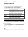
Programmable Parameters
Selecting program mode
LED meaning in program mode
Parameter Adjustment Table – Page One
Parameter Adjustment Table – Page Two
Parameter Adjustment Table – Page Three
Creating Your own Set of Operation Modes
Resetting Parameters to Factory Values
50
50
57
57
59
60
61
62
62
5
Programming the DX System
Downloading the correct DX wizard file
64
64
©Unique Perspectives Ltd.
www.click2go.ie
Page 3
User Manual
Genie Joystick
Nov 07
Programming Methods & Tools
Dynamic Wizard
Hand Held Programmer (HHP)
Auto download
DX System Parameters
Drive program parameters
Keypad & Speed Pot Parameters
Joystick Parameters
Actuator Parameters
Lighting Parameters
67
67
67
68
69
70
71
72
73
75
6
Battery Warnings, Diagnostics and Fault Finding
Battery warning conditions
Battery high warning condition
Battery Low warning condition
Low capacity warning condition
Diagnostics and Fault Finding
Flash Code
Limp Mode
69
69
69
69
69
70
70
73
7
Maintenance
74
8
Safety and Misuse Warnings
Know the Risks and Limitations
75
76
9
EC Declaration Of Conformity
77
10
Warranty
79
11
Sales and Service Information
80
12
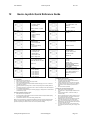
Genie Joystick Parameter Quick Reference
81
History of improvements and changes
82
©Unique Perspectives Ltd.
www.click2go.ie
Page 4
User Manual
Genie Joystick
Nov 07
SECTION ONE
USER OPERATION
©Unique Perspectives Ltd.
www.click2go.ie
Page 5
User Manual
1
Genie Joystick
Nov 07
Introduction
With the Genie joystick you can control your wheelchair, access a computer,
operate environmental and communication aid devices all from the same
joystick.
Just one switch or a flick of the joystick is all that is required to switch modes
from, for example, driving the wheelchair to moving the computer mouse and
back again. It is simple to use with no complex menus or displays.
The Genie joystick can be fitted to any wheelchair that is fitted with a DX power
module. It is a master remote and therefore replaces the existing joystick. No
other equipment is required.
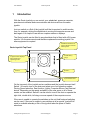
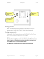
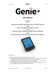
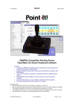
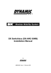
InfraRed transmitter for
mouse emulator located
behind panel.
Genie Joystick Top Panel
6 LED battery
gauge
7-segment LED displays
Drive Profile and
Operating mode.
Switch 1
1
2
Switch 2
System Status LED
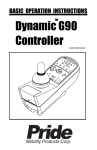
On the top panel of the joystick are two switches and the joystick element itself.
Switch 1 is used to turn on the chair and select one of six operating modes;
Driving, Speed selection, Seat function, Lights, Computer Mouse, and External
device. Depending on the needs and ability of the user some or all of these
modes can be enabled. Switch 2 can be used to turn off the chair or operate the
right click, double click, left drag or mouse speed of the computer mouse.
If the user is unable to operate the switches on the unit itself external switches
can be used. If the user is unable to use switches at all a special “joystick flick”
mode is available whereby a flick of the joystick takes the place of switch
selections.
©Unique Perspectives Ltd.
www.click2go.ie
Page 6
User Manual
Genie Joystick
Nov 07
At the left hand side of the joystick element a 7 segment display indicates the
operating mode. At the right hand side of the joystick element is the battery
gauge. The DX system status LED is located in the centre of the unit between
Switch 1 and 2.
The Genie joystick has a standard DXBUS connector so that it may be
connected to the DX power module. The Genie joystick can be used to control
any powered wheelchair which is fitted with a DX Power Module.
The Genie joystick and the associated DX Power Module are fully
programmable to cater for a wide range of chair types and user needs. Correct
installation and programming are essential to ensure optimum performance and
safety.
The operation mode of the Genie joystick can be programmed without the need
of a DX Hand Held Programmer or a Dynamic Wizard. Programming of the
Genie joystick is performed on the device itself.
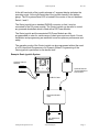
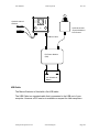
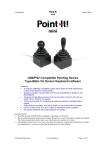
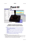
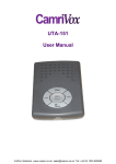
Example Genie joystick System
Optional external
switches
1
2
Optional Remote
Joystick Module or
Dual Control.
DXBUS Cable
DX Power Module
(PM).
24V Wheelchair
Battery
©Unique Perspectives Ltd.
www.click2go.ie
Page 7
User Manual
2
Genie Joystick
Nov 07
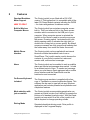
Features
Gearless/Brushless
Motor Support
NEW TO REV E
The Genie joystick is now fitted with a DX UCM
version 2. This implies that it is compatible with all the
latest DX Power Module variants including the DXGB
– for chairs with gearless / brushless motors.
Built-In Wireless
Computer Mouse.
The Genie joystick has a wireless computer mouse
built-in. This is an infra-red link to the Genie mouse
emulator which connects into the USB port of your
computer. When computer access is selected the
joystick on the Genie is used to move the mouse on
the screen. Pressing switch 1 activates the left click,
whilst pressing switch 2 activates the right click (or
double click or drag lock or mouse speed). By default
mouse movements are fully proportional meaning that
the further away from centre the faster the mouse.
Mobile Phone
Interface
The Genie joystick can be supplied with an internal
bluetooth module that enables control over a
SmartPhone. The joystick can be used to browse the
contents of your phone’s contact list, make and
receive calls, and send text messages.
Alarm
The Genie joystick can be enabled to emit an audible
alarm and send a text message when switch 1 is held
for a defined period of time. To send a text message
alarm you must have a Genie equipped with a mobile
phone interface and the SmartPhone must be
switched on and connected.
On-Screen Keyboard
included.
The Genie mouse emulator is supplied with a free
copy of TypeMatic on-screen keyboard software. This
software can be used to type text into any Windows
application and includes powerful word prediction and
completion features.
Mode selection with
just one switch
The Genie joystick accommodates people who can
operate a joystick but who find it difficult to operate the
buttons on a standard joystick control. With the Genie
joystick just one switch or a flick of the joystick is all
that is required to change operating modes.
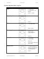
Driving Mode
Standard wheelchair driving mode. Drive profile is
displayed in the 7 segment display.
©Unique Perspectives Ltd.
www.click2go.ie
Page 8
User Manual
Genie Joystick
Nov 07
Seat function Mode
A seat symbol is displayed in the 7 segment display.
Left/Right movements of the joystick selects which
seat actuator to operate. Forward/Back movements of
the joystick operate the chosen actuator. The 7
segment display provides feedback to the user as to
which actuator is selected.
Lights Mode
A forward movement of the joystick turns on or off the
side lights. A backwards movement of the joystick
turns on or off the hazard lights. Left/Right movements
of the joystick turn on or off the indicators (unless the
hazards are on).
Computer Access
A “C” is displayed in the 7 segment display. By moving
the joystick the mouse on the computer is moved
about the screen. Switch 1 operates the left click.
Switch 2 operates the right click, double click or drag
lock or mouse speed.
To exit Computer Access mode switch 1 is held for a
predefined length of time.
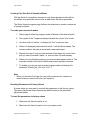
External Access
The Genie joystick can be connected to an
environmental control or communication aid device.
The joystick can then be used to make selections on
the external device. For example the joystick can be
used to highlight a cell on a grid of communication
symbols using left/right and up/down movements. The
cell can be selected by clicking switch 1.
To exit External Access mode switch 1 is held for a
predefined length of time.
Direct connection to
GEWA PROG III
environmental control
transmitter.
The Genie joystick can be interfaced to any
environmental control transmitter but is designed to be
specifically connected to a GEWA PROG III. In this
instance the button on the PROG is highlighted using
left/right and up/down movements of the joystick and
selected by pressing switch 1.
USB Interface
A USB interface cable allows the Genie to be
connected to the USB port of an “on-chair” computer
or communication device. When external access is
selected the joystick on the Genie is used to move the
mouse pointer on the external device. Switch 1
operates the Left Click or Select.
©Unique Perspectives Ltd.
www.click2go.ie
Page 9
User Manual
Genie Joystick
Nov 07
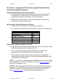
Drive Profile Select
Forward/Back movements of the joystick select the
desired drive profile. Alternatively the drive profile can
be chosen on start up by holding down switch 1 until
the drive profile number starts changing and releasing
switch 1 when the desired number is displayed.
Power Off
This is a special mode that simply turns off the chair. It
is for users who cannot operate a second switch.
Mode Selection
methods
Several different methods of selecting the above
modes are possible. Choosing the correct selection
method is an important part of setting up the Genie
joystick to meet the needs and abilities of the user.
“Switch Only”
By pressing and holding switch 1 the display toggles through
symbols representing each mode. Release switch 1 when the
desired mode is displayed.
“Switch + Joystick”
Press switch 1 to enter mode selection. The display shows a
symbol representing the first mode. Pressing switch 1 again goes
on to the symbol for the next mode. Deflecting the joystick
forward selects the mode that is displayed.
“Joystick + Switch”
Press switch 1 to enter mode selection. The display shows a
symbol representing the first mode. Deflecting the joystick
forward goes onto the symbol for the next mode. Deflecting the
joystick backwards goes back to the symbol for the previous
mode. Pressing switch 1 selects the mode that is displayed.
“Joystick only”
A backwards flick of the joystick selects mode selection. The
display shows a symbol representing the first mode. Deflecting
the joystick forward goes onto the symbol for the next mode. A
backwards flick of the joystick selects the mode that is displayed.
Programming button
The selection method of the Genie joystick, the
number and type of operating modes and other
options can be programmed without the use of a
computer or other external device. The program button
is located through a hole at the front of the device and
pressing this sets the Genie joystick in program mode.
All the options can be set by using switch 1, switch 2,
the 7 segment display and the battery gauge.
RJM compatible
The Genie joystick is compatible with all DX remote
joystick modules and these can be used instead of the
joystick on the Genie if so required. The only
restriction in this method of operation is that mouse
movements are always non-proportional, i.e. a fixed
speed.
©Unique Perspectives Ltd.
www.click2go.ie
Page 10
User Manual
Genie Joystick
Nov 07
Battery gauge
Battery charge level is indicated by a set of 6 LEDs.
These are arranged from bottom to top as 2 red, 2
yellow, and 2 green.
System status
Faults within the DX system are indicated by flashing
the system status LED located between switch 1 and 2
Programming socket
HHP / Wizard socket
The standard HHP / Wizard socket for programming
the DX system. Located underneath the device.
Standard DXBUS
connection
For connecting the Genie joystick, with a DXBUS
cable to the DX power module.
Battery charger
Due to space restrictions the battery charger socket is
not located on the Genie joystick itself but on a
separate DX BUS lead (DX part no: DX-ACC3).
3.5mm Switch Inputs
For people who cannot use Switch 1 and Switch 2 you
can connect external switches such as TASH buddy
buttons etc.
Knob Options
A number of different knob options are available
including Ball, Carrot, Chin, T bar, Sponge etc.
©Unique Perspectives Ltd.
www.click2go.ie
Page 11
User Manual
3
Genie Joystick
Nov 07
Operation
Turning on the Genie joystick.
To turn on the Genie joystick press Switch 1. The 7 segment display will show a
“-“ symbol and after a short moment will display the current drive profile.
If you have the “Accidental_Hits” option enabled you must hold Switch1 for at
least 1 second before the Genie joystick will power up properly. This avoids
involuntary movements on an external switch.
For more information on Genie joystick option see Section 2 Chapter 4.
Driving the Chair.
Driving is the default operation mode. It is automatically selected when the
wheelchair is turned on or when another operation mode is finished.
To drive the chair forward deflect the joystick forward. To drive the chair
backwards deflect the joystick backwards. To drive the chair to the right deflect
the joystick to the right. To drive the chair to the left deflect the joystick to the
left.
Warning: If the driving performance is poor or erratic consult your service agent
immediately.
Selecting another operation mode.
There are 7 other operation modes apart from driving. These are:Mode
1.
Computer Mouse
2.
External Access
3.
Mobile Phone
©Unique Perspectives Ltd.
Symbol
www.click2go.ie
Page 12
User Manual
Genie Joystick
4.
Seat Function
5.
Lights
6.
Change Drive Profile
7.
Power Off
Nov 07
The number of available modes and the order in which they are presented to the
user can be defined. The default number of modes and order is as above.
There are 4 different methods of mode selection. Choosing the right selection
method is an important part of the assessment process and will determine how
successful a user will be in using the Genie joystick.
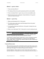
Method 1 – Switch Only
1. Press and hold Switch 1
2. The display will show the symbol representing the first mode available.
3. As long as Switch 1 is held the display will toggle through the other symbols.
4. Release Switch 1 when the desired symbol is displayed.
5. The Genie joystick enters that mode.
Method 2 – Switch + Joystick (Default method)
1. Press and release Switch 1
2. The display will show the symbol representing the first mode available.
3. Use forward and backwards deflections of the joystick to display the mode
you want to enter.
4. Select and enter the mode by pressing Switch 1.
©Unique Perspectives Ltd.
www.click2go.ie
Page 13
User Manual
Genie Joystick
Nov 07
Method 3 – Joystick + Switch
1. Press and release Switch 1
2. The display will show the symbol representing the first mode available.
3. Press and release Switch 1 again to step on to the next available mode.
4. When the desired mode is displayed a forward deflection of the joystick
selects and enters the mode.
Method 4 – Joystick Only
1. Make a quick backwards “flick” of the joystick.
2. The Genie enters mode selection and the display will show the symbol
representing the first mode.
3. Use forward and backwards deflections of the joystick to display the mode
you want to enter.
4. Make a second backwards “flick” of the joystick to enter the displayed mode.
WARNING: Once a mode is being selected or when a mode has been entered it
is no longer possible to drive the wheelchair. It is extremely important, therefore,
to be in a safe location before selecting or entering another operation mode.
Driving is only possible again after the mode has been finished.
For all selection methods except “Joystick Only” a mode is finished by pressing
Switch 1 (pressing and holding Switch 1 in computer mouse and external
access modes). With a “Joystick Only” selection method a mode is finished by a
backwards “flick” of the joystick.
Computer Mouse mode.
When computer mouse mode is selected the joystick controls the mouse on the
computer (provided that the mouse emulator is connected and the wheelchair is
within range. See page 35 for details on fitting the mouse emulator).
A forward deflection of the joystick moves the mouse pointer up the screen. A
backward deflection of the joystick moves the mouse pointer down the screen. A
©Unique Perspectives Ltd.
www.click2go.ie
Page 14
User Manual
Genie Joystick
Nov 07
left deflection of the joystick moves the mouse pointer to the left and a right
deflection of the joystick moves the mouse pointer to the right.
Pressing Switch 1 performs a Left Click, whilst pressing Switch 2 performs a
right Click. Switch 2 can also be programmed to be either “Double Click”, “Left
Drag Lock”, “Mouse Speed” or as a direct way to exit mouse mode. See page
51.
In Windows XP it is possible to change the speed of the mouse pointer. See
page 47.
To exit computer mouse mode press and hold Switch 1 until the Genie joystick
emits a beep. The length of time that the switch must be held can be adjusted
by the “Exit_Time” parameter.
For people who are unable to use the computer keyboard an on-screen
keyboard software entitled “TypeMatic” is provided. This allows a user to select
keys and words from a grid on the screen and type into any Windows program.
The software is discussed in the next chapter.
Joystick only mode
If the selection method is set to “Joystick Only” the computer mouse mode
operates in a different way.
A left “flick” of the joystick performs a left click. A right “flick” of the joystick
performs a right click. A forward “flick” of the joystick performs a “double left
click” and a backwards “flick” of the joystick exits computer mouse mode.
Note that in this mode the mouse will not begin to move until after the “flick”
time, which is set by the “Time_Base” parameter.
External Access mode.
When external access mode is selected the joystick controls the external device
(provided that the external device has been connected to the Genie joystick with
the correct cable. See page 38 for details on interfacing to external devices.
Devices with a 5 switch input
These devices can be controlled in exactly the same way as if a nonproportional joystick, such as a TASH mini joystick or Star switch, were directly
connected to it. The Genie joystick takes the place of such a switch.
The genie joystick expects that the device presents a grid of options to the user
and that forward/back and left/right deflections will highlight an individual cell in
the grid whilst pressing Switch 1 will select and activate the highlighted cell. The
grid might be a set of communication symbols on a communication aid (for
©Unique Perspectives Ltd.
www.click2go.ie
Page 15
User Manual
Genie Joystick
Nov 07
example a Cameleon CV) or the buttons on an environmental control transmitter
(for example the GEWA prog).
Devices with 2x3.5mm switch inputs
These devices would normally be controlled by 2 switches and would implement
some sort of scanning mechanism. One switch is used to scan the cells of a grid
whilst the other is used to activate the highlighted cell.
With the Genie joystick the switches are replaced by deflections of the joystick.
A forward deflection is used to scan the cells of the grid whilst a backwards
deflection is used to activate the highlighted cell. Again the grid could be a set of
communication symbols on a communication aid (a Words+ MessageMate for
example) or the buttons of an environmental control transmitter (a TASH Relax
for example).
Controlling 2 external devices
If 2 external devices are connected they must both be controlled as described
above except that Left/Right deflections of the joystick are used for the second
device.
To exit external access mode press and hold Switch 1 until the Genie joystick
emits a beep. The length of time that the switch must be held can be adjusted
by the “Exit_Time” parameter.
Joystick Only selection mode
When the selection method is set to “Joystick Only”…
? a forward “flick” of the joystick is the equivalent of pressing Switch 1.
? exit external access mode with a backward “flick” of the joystick.
Mobile Phone mode (optional)
When mobile phone mode is selected the joystick controls a Smart Phone. The
phone must be Bluetooth equipped and running Windows Mobile 2003 operating
system. Joystick deflections are used to navigate the menus on the phone and
make and receive telephone calls. On screen keyboard software running on the
phone allows you to compose and send text messages. For further details on
using your Genie joystick to control a Smart Phone and how to install the
software see the “ClickToPhone” user manual.
To exit mobile phone mode press and hold Switch 1 until the Genie joystick
emits a beep. The length of time that the switch must be held can be adjusted
by the “Exit_Time” parameter.
Joystick Only selection mode
©Unique Perspectives Ltd.
www.click2go.ie
Page 16
User Manual
Genie Joystick
Nov 07
When the selection method is set to “Joystick Only”…
? a forward “flick” of the joystick is the equivalent of pressing Switch 1.
? exit mobile phone mode with a backward “flick” of the joystick.
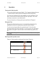
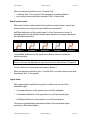
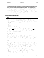
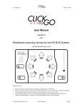
Seat Function mode.
When seat function mode is selected the joystick is used to select, extend and
retract actuators (so long as they are fitted to the wheelchair).
Left/Right deflections of the joystick select 1 of the 5 actuators to control. A
flashing segment in the display indicates which actuator is currently selected as
the table below illustrates.
Back Rest
Back Tilt
Seat Height
Foot Rest L
Foot Rest R
Actuator 1
Actuator 2
Actuator 5
Actuator 3
Actuator 4
Forward/Back deflections of the joystick are used to extend or retract the
selected actuator.
NOTE: It is possible to edit the actuator list so that only those actuators that are
fitted on the chair are displayed in seat function mode. See Section 2 Chapter 4.
To exit seat function mode press and release Switch 1.
When the selection method is set to “Joystick Only” exit seat function mode with
a backward “flick” of the joystick.
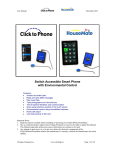
Lights mode.
When lights mode is selected the joystick is used to turn on and off the
wheelchair lights.
?
A forward deflection of the joystick turns on/off the sidelights.
?
A backwards deflection of the joystick turns on/off the hazard lights.
?
Left/Right deflections of the joystick turn on/off the indicators.
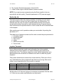
The seven segment display indicates the status of the wheelchair lights
according to the following table:-
©Unique Perspectives Ltd.
www.click2go.ie
Page 17
User Manual
Side Lights
Genie Joystick
Left Indicator
Right Indicator
Nov 07
Hazards
To exit lights mode press and release Switch 1.
When the selection method is set to “Joystick Only” exit lights mode with a
backward “flick” of the joystick.
Change Drive Profile mode.
When Change Drive Profile mode is selected the joystick is used to select the
drive profile (sometimes referred to as the speed). The seven segment display is
used to indicate the selected drive profile number.
Use forward/back deflections of the joystick to select the desired drive profile
number. A forward deflection increases the drive profile number while a
backwards deflection decreases the drive profile number.
To exit change drive profile mode press and release Switch 1.
When the selection method is set to “Joystick Only” exit change drive profile
mode with a backward “flick” of the joystick.
Note that the number of Drive profiles that can be selected is limited by the
Max_Profile_Number. For details on changing this and other options see
Section 2 Chapter 4.
Power Off mode.
When power off mode is selected the Genie joystick turns off.
You can also turn off the wheelchair from any mode with the exception of
computer access mode by pressing and releasing Switch 2.
Making an Alarm.
In any mode the user can generate an alarm by pressing and holding Switch 1
until an ‘A’ is displayed in the 7 segment display and the Genie starts beeping
rapidly. There are 2 types of alarm.
1- Audible alarm
2- Audible alarm + Text Message Alarm
©Unique Perspectives Ltd.
www.click2go.ie
Page 18
User Manual
Genie Joystick
Nov 07
The type of alarm is set by the “Alarm” parameter.
When the second type of alarm is chosen and the Genie is equipped with a
BlueTooth interface and the SmartPhone is switched on and connected the
Genie instructs the SmartPhone to send a pre-written text message is sent to a
specific number. For more information see the “ClickToPhone” user manual.
The length of time that the switch must be held to generate an alarm can be
adjusted by the “Exit_Time” parameter.
For details on changing this and other options see Section 2 Chapter 4.
©Unique Perspectives Ltd.
www.click2go.ie
Page 19
User Manual
4
Genie Joystick
Nov 07
Type-Matic Software
Installing the Software
1. Insert the CDROM into your CD-ROM drive
2. If the installation program does not “autorun” then choose ‘Run’ from the
Windows Start menu and continue with step 3, otherwise jump to step 5.
3. Type d:\setup.exe. (if your CD-ROM drive is not drive D, type the appropriate
letter instead.)
4. Choose OK.
5. Follow the instructions on the screen.
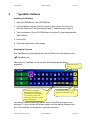
Running the Program
Run TypeMatic by choosing Programs from the Start menu and clicking on the
TypeMatic icon.
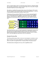
When you run TypeMatic for the first time the following default Grid is
presented:Standard keyboard
keys.
5 Special keys. Spacebar,
Backspace, Enter, Shift and
SentenceBar. To view help text
on a character position the
mouse over the cell and pop-up
help text will appear.
Links to other grids for numbers,
punctuation and function keys.
Now launch a word processing program such as WordPad and open a new
document. To type, position the mouse pointer over the desired character and
click. The character should appear in your new document.
©Unique Perspectives Ltd.
www.click2go.ie
Page 20
User Manual
Genie Joystick
Nov 07
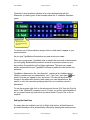
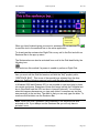
Typematic’s word prediction displays a list of words beginning with the
characters you have typed. In the example below the ‘h’ character has been
typed.
Word predictions
for word beginning
with ‘h’.
To choose one of the predictions simply click on it and watch it appear in your
word document.
As you type TypeMatic will remember any new words you create.
When you type a space, TypeMatic tries to predict the next word in the sentence
you are typing. Because this prediction is based on previous sentences you
have written this prediction will not begin right away. The more you repeat
certain sentences the more TypeMatic will learn to predict the next word in the
sentence.
TypeMatic’s abbreviation file, ‘shorthand.txt’, contains a list of abbreviations.
Initially it contains only one abbreviation, ‘hau’. Type ‘hau’, then enter
and
watch ‘How are you’ appear in your document. You can edit shorthand.txt
located in the application directory and create your own abbreviations. Be
careful to only use character groupings which do not constitute a word in
themselves.
To quit the program right click on the window and choose ‘Exit’ from the Pop-Up
menu. If the ‘UpdateFile’ property is set to ‘Prompt’ you will be asked whether or
not you want to save any new words you have written. Choose Yes or No as
required.
Setting the Dwell time
For users who are unable to use Left or Right click buttons a Dwell feature is
provided whereby a cell is automatically selected by keeping the mouse pointer
©Unique Perspectives Ltd.
www.click2go.ie
Page 21
User Manual
Genie Joystick
Nov 07
still for a certain length of time over the desired cell. This time is called the dwell
time and can be set between 1 and 5 seconds. Right click on any cell in the grid
and select Dwell time from the PopUp menu.
Now when you position the mouse pointer over a cell and keep it still for dwell
time the contents of the cell will be typed into the active application, i.e. the cell
is automatically selected without having to make a click.
Furthermore when you select a Dwell time a set of buttons representing Left
click, Left Drag and Right click appear in the left hand side of the TypeMatic
window. These allow you to generate mouse clicks in other applications by
keeping the mouse pointer still for the dwell time over the control you want to
click.
Left Click
Left Dbl Click
Left Drag
Right Click
First select the mouse click you want to generate by keeping the mouse pointer
still over the button representing the desired mouse click. After the button is
selected (down position) move the mouse pointer over the control you want to
click in the other application and keep it still for the dwell time.
Using the Sentence Bar
The Sentence Bar feature allows a user you to pre-prepare a sentence or word
before sending it to the active application. To activate the sentence bar Right
Click on any cell in the grid and click on Sentence Bar in the pop-up menu.
The Sentence bar will appear at the top of the TypeMatic window.
©Unique Perspectives Ltd.
www.click2go.ie
Page 22
User Manual
Genie Joystick
Nov 07
Special key also
activates the
sentence bar.
When you have finished typing your word or sentence click on the Enter cell
to send the text in the sentence bar to the active application.
To de-activate the sentence bar Right Click on any cell in the Grid and click on
Sentence Bar in the pop-up menu.
The Sentence bar can also be activated from a cell in the Grid identified by the
following icon:
You would use this method if a person is unable to perform a Right Click.
Note: If this cell does not appear in the Grid you are using, but you require it,
then you must edit the Grid and create a cell with the “Key” property set to
“SENTENCE_BAR”. This is one of the special keys selected from the drop
down list. See the following page on how to edit the cells in the Grid.
In Windows 2000 and Windows XP it is not possible to input text letter by letter
into certain text boxes. Examples of these text boxes include the FileName text
box in WordPad® and the URL text box in Internet Explorer®. You will know
when this happens because as you type each letter it overwrites any text that
was previously in the text box. The result is that you can only type one letter. To
overcome this limitation use the Sentence Bar.
Note: When you close TypeMatic it will remember if the Sentence Bar was
activated or not. If you always use the Sentence Bar you will only have to
activate it once.
©Unique Perspectives Ltd.
www.click2go.ie
Page 23
User Manual
Genie Joystick
Nov 07
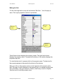
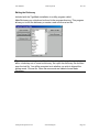
Editing the Grid
To edit a Grid right click on any cell and choose ‘Edit Grid…’ from the pop-up
menu. The Layout properties window is presented.
Property
values
Property
names
Property
help text
The left hand column displays the property names. The right hand column
displays the property values. The panel at the bottom of the window displays the
properties help text.
To view the help text of a property click on the property name. The help text for
the property appears in the panel at the bottom of the window.
When you click on the property name a control appears in the property value
field. The type of control depends on the property type, for example a drop down
list for Grid Size, a file open button for Picture, a text entry control for Caption.
Use the control to edit the property value.
©Unique Perspectives Ltd.
www.click2go.ie
Page 24
User Manual
Genie Joystick
Nov 07
Properties
Layout
You can have any number of grids with TypeMatic. Click the FileSave
button to save the current Grid or click the FileOpen button to open
another.
BackColor
The color of the background.
BevelStyle
The bevel style of cells in the grid. Can be set to none, Inset or Raised.
BevelWidth
The width of a cell bevel. Can be set between 1 and 8.
CellGap
The gap between cells. Can be set between 0 and 8.
CellSize
The size of the cells in the grid. Can be set to 16x16, 32x32 or 64x64.
Font
The font used throughout the grid.
GridPosition
The start-up position of the grid on the screen.
GridSize
The size of the grid. The smallest size is 4x4 cells, the largest is 8x10
cells.
HighlightColor
The color used to highlight cells.
Abbreviations
Specifies whether or not the abbreviation feature is enabled. The
abbreviation list is stored in the file ‘shorthand.txt’ in the application
directory. You can edit it to add more abbreviations using notepad.
WordPrediction
The type of word prediction used. Can be set to none, current word or
current plus next word. When set to none the word prediction column is
hidden.
UpdateFile
Specifies how the word prediction file ‘typematic.dic’ is updated with the
words written and chosen by a user. Can be set to Always, Never or
Prompt. If set to prompt the user is asked whether or not they wish to
save any new words when they quit the program.
*CellColor
The color of a cell. If the cell is transparent this property has no effect.
*FontColor
The color of the font in the cell.
*Key
The key(s) to be pressed (simulated) when the cell is selected. Use ‘+’ for
SHIFT, ‘%’ for ALT and ‘^’ for CTRL. These special keys have a toggle
function. To specify an actual plus sign use ‘{+}’. For ‘^’ use ‘{^}’, for ‘%’
use ‘{%}’. You can select other special keys from the listbox.
Note than when you select a key the text is automatically assigned to the
caption. You can have the caption text different from the key text but
always set the key text first, then the caption text.
*Caption
The text that appears in the cell.
*HelpText
The help text for the cell which will be displayed when the mouse is
paused over the cell.
©Unique Perspectives Ltd.
www.click2go.ie
Page 25
User Manual
Genie Joystick
Nov 07
*Transparent
Specifies whether or not a cell is transparent. A transparent cell takes on
the color of the background when not selected and the color of the
highlight when selected.
*Picture
Each cell can contain a picture (bitmap or icon only).
*NextGrid
You can link a cell to another grid by specifying the file here. In this way
you can have links to grids of numbers and punctuation. Always
remember to have a link back to the main grid!
Editing the properties of a cell
Properties beginning with an ‘*’ are specific to an individual cell and only effect
the selected cell. To edit the property of a cell, for example it’s key, click on the
cell in the main window, then click the property name called ‘key’ and edit it’s
content.
A special case is the column of word predictions. These cells have the same
properties. In other-words if you set the cell color for a word prediction cell it
effects all word prediction cells.
Editing the ‘general’ properties of the Grid
Properties which do not begin with a ‘*’ effect the general look and functionality
of the Grid. For example the GridSize is a general property.
Saving and Opening layout files
When you have finished editing properties you can save the Grid as a file on
your hard disk. The files are called ‘tlf’ files: ‘Typematic Layout File’. To save a
Grid click on the first property called ‘layout’. A File Open and File Save button
appear in the property value field. Click the File Save button to save your newly
edited Grid.
Typematic comes with a selection of files to illustrate different Grids. These files
are called small.tlf, standard.tlf and colorful.tlf and are located in the application
directory. To load a Grid click on the first property called ‘layout’ then click on
the File Open button, locate the desired file and choose OK.
Note: When you close the Layout properties window TypeMatic will remember
which Grid is in use and will load this Grid the next time it is run.
You can also open grids directly from the main TypeMatic window by right
clicking on any cell and choosing Open Grid from the popup menu.
©Unique Perspectives Ltd.
www.click2go.ie
Page 26
User Manual
Genie Joystick
Nov 07
Editing the Dictionary
Included with the TypeMatic installation is a utility program called
MakeDictionary.exe which can be found in the program directory. This program
allows you to edit the dictionary or create a new one from a text file.
Tip: If you wish to merge a text file with the existing dictionary, for example to
add a vocabulary set to a user’s dictionary, first open the dictionary file and then
open the text file. You will be prompted as to whether you wish to discard the
exiting words. Choose No. Once the new words are loaded choose Make
Dictionary.
©Unique Perspectives Ltd.
www.click2go.ie
Page 27
User Manual
5
Genie Joystick
Nov 07
Batteries and Charging
Battery Type
The DX System is designed to perform optimally with either Lead-Acid or Gel
Cell 24 V deep cycle batteries, rated at 20 – 120 Amp hours. The maximum
average discharge rate must not exceed half the rated capacity, in Amp hours.
Battery Charging
Due to space restrictions the battery charger socket is not located on the Genie
joystick itself but on a separate DX BUS lead (DX part no: DX-ACC3)..
Progress of the charge can be monitored by turning on the Genie Joystick and
watching the battery gauge.
Battery Gauge
The battery gauge provides true, useable battery capacity information. A full
battery with at least 85% of rated capacity, is represented by all 6 LEDs lit.
Some new batteries can start with as little as 80% capacity, developing higher
capacity in their early life (sometimes up to 110%), before slowly deteriorating
over their rated life.
As the battery voltage drops, the number of LEDs lit reduces from top to bottom.
When only the red LEDs are lit, the available battery capacity is typically less
than 10%. At this level and below, the Battery Gauge flashes to alert the user
that the wheelchair is running on reserve capacity. The battery capacity will
reduce more rapidly in the reverse capacity range.
Battery Saver
The Battery Saver is a feature programmed into the DX Remote. When the
battery capacity is in the reserve range (below 21V), the wheelchair
performance is reduced. This is to preserve the life of the battery by
encouraging the user to recharge the battery before it becomes harmfully flat.
Operating the wheelchair with more than two LEDs of the battery gauge lit will
generally give normal wheelchair performance. This is provided that the battery
size and the PM program settings are matched to the wheelchair.
©Unique Perspectives Ltd.
www.click2go.ie
Page 28
User Manual
6
Genie Joystick
Nov 07
Maintenance
1. The Genie Joystick system should be regularly checked for integrity. Loose,
damaged or corroded connectors or terminals, or damaged cabling should
be reported to your Service Centre and be replaced immediately.
2. The cabling of Genie Joystick System including Switch cables, DXBUS
cable, Charger cable and Battery cables, should be regularly checked for
integrity. They should never be loose. Cables should be neatly attached to
the wheelchair frame and mounts so that no possibility exists for a cable to
become snagged on the moving parts of the wheelchair itself, the person
sitting in the wheelchair, and/or items external to the wheelchair such as
door handles etc.
3. All switches connected to the Genie Joystick should be regularly tested to
ensure that they function correctly.
4. During storage and transport of your wheelchair ensure that there is no
possibility that switch 1 can inadvertently by pressed thereby causing the
chair to turn on and possible enter a drive state. Always disengage the motor
gears and disconnect any external switches.
5. Under no condition should a latching switch be connected to the Genie
Joystick. Only connect non-latching switches.
6. The Genie Joystick components and other wheelchair parts should be kept
free of dust, dirt and liquids. If necessary wipe with a cloth dampened with
warm water or alcohol. Do not use solvents or abrasive cleaners.
7. Where any doubt exists, consult your nearest Service Centre or Agent.
8. There are no user-serviceable parts within the Genie Joystick. Do not
attempt to open the case.
9. In accordance with the requirements of CE marking of this device and the
Company’s policy, it is requested that re-occurring faults or defects are
reported back to Unique Perspectives Ltd.
Warning !! If the Genie Joystick is damaged in any way, or if internal damage
may have occurred (for example by being dropped), have it checked by qualified
personnel before operating.
©Unique Perspectives Ltd.
www.click2go.ie
Page 29
User Manual
7
Genie Joystick
Nov 07
Safety and Misuse Warnings
Do not install, maintain or operate this equipment without reading,
understanding and following the proper instructions and manuals, otherwise
injury or damage may result.
The completed installation must be thoroughly checked, and all programmable
options must be correctly adjusted for safe operation prior to use.
A warning must be conveyed to the wheelchair operator that the controller could
cause the chair to come to a sudden stop. In situations where this may affect the
safety of the user, this will require the fitting and wearing of a seat belt.
Performance adjustments should only be made by professionals of the health
care field or persons fully conversant with this process and the driver’s
capabilities. Incorrect settings could cause injury to the driver, bystanders,
damage to the chair and surrounding property.
After the wheelchair has been set up, check to make sure that the wheelchair
performs to the specifications entered in the programming procedures. If the
wheelchair does not perform to specifications, turn the wheelchair off
immediately and re-program. Repeat procedure until the wheelchair performs to
the specifications.
Do not operate the DX system if it behaves erratically, or shows abnormal
response, heating, smoke or arcing. Turn the system off, disconnect the battery
or open the battery overload switch, and consult your service agent.
Do not operate your DX system if the battery is nearly flat as a dangerous
situation may result due to a loss of power in an inopportune place.
Ensure the controller is turned off when not in use.
No connector pins should be touched, as contamination or damage due to
electrostatic discharge may result. Dummy sockets in unused DXBUS
connectors should be left in place unless a new module is added to the system.
Whilst designed to resist water penetration, under certain conditions moisture
might enter the Genie Joystick. Any spillage’s over the Genie Joystick should be
wiped dry without delay. The Genie Joystick may be used outdoors in light
drizzle conditions but should be protected from rain.
Most electronic equipment is influenced by Radio Frequency Interference (RFI).
Caution should be exercised with regard to the use of portable communications
equipment in the area around such equipment. While the manufacturer has
©Unique Perspectives Ltd.
www.click2go.ie
Page 30
User Manual
Genie Joystick
Nov 07
made every effort to ensure that RFI does not cause problems, very strong
signals could still cause a problem. If RFI causes erratic behavior, shut the
wheelchair off immediately. Leave off while transmission is in progress.
In the event of a fault indicator flashing while driving (battery gauge and/or
status LED), the user must ensure that the system is behaving normally. If not,
the system must be turned off and a Service Agent called immediately.
Report any malfunctions immediately to your Service Agent.
Know the risks and limitations
Like any mechanical propelled vehicle there are certain risks involved.
The driver is responsible for any damage or injury that may occur to a party as a
result of using a powered wheelchair. If the driver cannot assume responsibility
due to age or disability then a carer must be present and be able to take over
control either using a stop switch or a dual control in case of an emergency. You
may wish to consider taking out insurance to cover any claims arising from such
an incident.
The most sensitive part of a Genie Joystick system is the joystick element itself.
The owner or carer must assume responsibility for regularly checking the
integrity of the joystick element and report any problems to the service agent
immediately.
©Unique Perspectives Ltd.
www.click2go.ie
Page 31
User Manual
Genie Joystick
Nov 07
SECTION TWO
INSTALLATION, ADJUSTMENT & FAULT
FINDING
©Unique Perspectives Ltd.
www.click2go.ie
Page 32
User Manual
1
Genie Joystick
Nov 07
Related Documentation
A DX based wheelchair control system may comprise between two and sixteen
DX compatible modules depending on the application. Each DX compatible
module has its own User Manual which describes the installation requirements
of that particular module.
This manual describes the Genie Joystick remote only and must therefore be
read in conjunction with the:
?
DX Power Module (PMB) Installation Manual
?
DX Hand Held Programmer (HHP) Manual
?
Dynamic Wizard Installation Sheet
?
Installation Manuals for all other DX Modules to be used in your application.
©Unique Perspectives Ltd.
www.click2go.ie
Page 33
User Manual
2
Genie Joystick
Nov 07
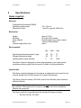
Specifications
Genie Joystick
Electrical
Compatible with standard DXBUS
Operating voltage range
Quiescent Current
18v – 32v d.c.
<1mA Off, typically 250mA On
Mechanical
Weight
Mounting
Case material
Size
Joystick Height above box
Approx 0.5 Kg
As required by installer
Extruded aluminum, plastic coated.
115mmx105mmx35mm
60mm
Environmental
Operating ambient temperature range
Storage temperature range
Operating and storage humidity
Min
Max
Units
-25
-25
0
50
70
90
ºC
ºC
%RH
The Genie Joystick is designed to resist water penetration, but under certain
conditions moisture might enter the control. Suitable for light precipitation.
Intended Use
The Genie Joystick is designed to be used as an alternative input control for the
Controls Dynamic DX Control System for Powered Wheelchairs.
The Genie Joystick contains a DX UCM (User Control Module) and is therefore
a Master Remote.
Warning ! In any DX System there can be only one master remote connected at
any one time. The system will not function correctly if more than one Master
Remote are connected.
The Genie Joystick is compatible with the following DX power modules:
? DX-PM, DX-PM1, DX-PM2
©Unique Perspectives Ltd.
www.click2go.ie
Page 34
User Manual
Genie Joystick
Nov 07
The Genie Joystick is compatible with the following Actuator modules:
? DX-CLAM, DX-TAM, DX-ARC5
The Genie Joystick can be used in conjunction with any DX Secondary remote.
The intended use of a secondary remote for this application would be if the
Genie joystick element itself is unsuitable for the user’s needs.
For compatibility with any other DX Module introduced by Controls Dynamic
please contact Unique Perspectives.
The Genie Joystick can be operated with external switches rather than the
buttons on the unit itself if required. The external switches should be of high
quality, professionally connected and regularly maintained. For details of wiring
and connections see Chapter 3 of this section.
The Genie Joystick is intended for use on Class A and B powered wheelchairs
only.
The Genie Joystick is not designed for use with any other control system.
Knob Options
A selection of different knob options are available and are illustrated below:-
©Unique Perspectives Ltd.
www.click2go.ie
Page 35
User Manual
Genie Joystick
Nov 07
Mouse Emulator
Electrical
Power Supply
Quiescent Current
5V 100ma DC from USB interface
100mA
Mechanical
Weight
Case material
Size
Approx. 250grams
Extruded aluminum, painted black.
115mmx55mmx35mm
Environmental
Operating ambient temperature range
Storage temperature range
Operating and storage humidity
Min
Max
Units
-25
-25
0
50
70
90
ºC
ºC
%RH
The Mouse Emulator is not designed for outdoor use.
Intended Use
The Mouse Emulator is a USB IBM compatible pointing device designed to
enable those individuals who cannot use a standard computer mouse the ability
to manipulate the windows mouse pointer using the Genie Joystick in computer
access mode.
The Mouse Emulator receives proprietary IrDA InfraRed signals from the Genie
Joystick and converts them into USB signals.
The Mouse Emulator is for indoor use only.
The Mouse Emulator can only be connected to a PC with a USB port. A PS/2
version is available for older computers on request.
The Mouse Emulator can only be used with a Genie Joystick.
©Unique Perspectives Ltd.
www.click2go.ie
Page 36
User Manual
3
Genie Joystick
Nov 07
Installation & Testing
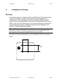
Mounting
A mounting system for the Genie joystick is available from Unique Perspectives.
Contact your supplier for details. This consists of a mounting plate and
extending arm. The mounting plate is fitted to the Genie joystick with 4xM4
screws. The mounting plate has a circular stud on its base which fits into a ringholder on the end of the extending arm. The square extending arm slides into a
corresponding tube located underneath the arm rest of the wheelchair. 5/8”
tubing or ¼” tubing options are available.
Warning !! The installation of the mount should be carried out by a qualified
technician or other professional. For safe fitting of the mounting plate to the
Genie joystick, select a screw length between 6mm and 10mm.
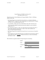
Dimensions of the mounting positions on the underside of the unit are shown
below:
36.5mm
36.5mm
©Unique Perspectives Ltd.
www.click2go.ie
Page 37
User Manual
Genie Joystick
Nov 07
Connections
The connection panel is located at the bottom of the device and is illustrated
below.
Switch 1 input
Switch 1 input
Switch Outputs to
external device
DX BUS
Connector
Programming
Switch.
Switch Inputs
On early units there is no program
switch. Press and hold switch 2 until
the unit beeps to enter program
mode (about 12 seconds).
For users who cannot operate the buttons on the Genie joystick itself 2x3.5mm
jack sockets are provided on the connection panel. You can connect any nonlatching switch to these sockets provided they are fitted with 3.5mm jack plugs.
Connector
Standard 3.5mm jack
plug
Pin
Tip
Sleeve
Signal
Switch
Switch common
Warning!!
A user’s switches must be connected professionally to the Genie Joystick by a
qualified technician. Unique Perspectives accept no responsibility or liability for
poorly made connections which may result in incorrect operation and possibly
dangerous operation of the Genie Joystick.
Under no condition should a latching switch be connected to the Genie Joystick.
Only use non-latching switches.
Unused sockets should be fitted with the plugs provided.
©Unique Perspectives Ltd.
www.click2go.ie
Page 38
User Manual
Genie Joystick
Nov 07
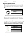
Switch Outputs & Interfacing to other devices.
To connect the Genie Joystick to an external device such as a communication
aid or environmental control device five solid state relay contacts are provided
on a 6 pin Mini DIN connector. These contacts reflect the state of the joystick
position and Switch 1 when external access mode has been selected by the
user.
6 pin Mini DIN.
Connector
1
2
3
4
5
?
?
6
Pin
1
2
3
4
5
6
Signal
Switch common
Joystick Left
Joystick Right
Joystick Down
Joystick Up
Switch 1
relays are current rated to 250ma
contacts are isolated from wheelchair electronics
The interface to the external device will depend upon the number of switch
inputs and connector type available on the external device. Several different
interface options are described below:Devices with a 9 pin D switch input
If the external device is capable of being controlled by a five switch device such
as a TASH mini joystick, wafer pad or star switch then device will have a 9 pin D
switch input. With a 6 pin Mini DIN to 9 pin D cable the Genie joystick can be
connected to such devices and operated in exactly the same way as if the five
switch device were connected to it. The pinout of the 9pin D is shown below:
Connector
9 Pin Male D
©Unique Perspectives Ltd.
Pin
1
2
3
4
5
6
7
8
9
Signal
Forward (Switch 2)
Backwards (Switch 3)
Left (Switch 4)
Right (Switch 5)
Select (Switch 1)
Switch common
www.click2go.ie
Page 39
User Manual
Genie Joystick
Nov 07
A 6 pin Mini DIN to 9 pin D cable is available for connection to devices with this
type of switch input.
Devices with 3.5mm jack switch inputs
Unfortunately most communication aid devices have only 2x3.5mm switch
inputs. In this case the Genie joystick can be wired to the device so that a
forward deflection of the joystick activates the switch 1 input of the external
device (normally the “select”) and a backwards deflection of the joystick
activates the switch 2 input of the external device (normally the “advance” or
“step”).
A 6 pin Mini DIN to 2x3.5mm jack plug cable is available for connection to such
devices.
The GEWA PROG environmental control interface
The switch input of the GEWA PROG III is also a 6 pin Mini DIN connector
whose pin-out matches that of the Genie joystick. To operate the PROG from
the joystick it is necessary to put the PROG in joystick input mode. You can do
this by pressing “P+5”, followed by “3” on the PROG. Consult the PROG
manual for further details.
A pin-to-pin Mini DIN cable is available for connection to this device
Interfacing to GEWA Progress ECU.
A special interface cable is required whose pin-out is described below and the
Genie joystick parameter “External Device” must be set to “3”. See Section 2
Chapter 4 for details on adjusting Genie joystick parameters. The Progress
should be set for 2 switch manual row/column scanning. When external access
is selected, downward deflections of the joystick select the row. Right hand
deflections select the cell within that row. And a final downward deflection
activates the chosen cell. It is important to carry out the sequence of deflections
as described otherwise the Progress may get out of step with the Genie. If this
happens simply exit external access mode and re-enter it.
Genie Joystick
Pin
Signal
1
Switch common
2
3
4
5
6
Joystick Left
Joystick Right
Joystick Down
Joystick Up
Switch 1
©Unique Perspectives Ltd.
Progress
Pin
Jack 1&2,
Sleeve
Signal
Switch common
Jack 2, Tip
Jack 1, Tip
Switch 2 signal
Switch 1 signal
www.click2go.ie
Page 40
User Manual
Genie Joystick
Nov 07
A Mini DIN cable to 2 3.5mm jacks is available for connection to this device
Interfacing to an environmental control unit and a communication aid.
To interface to more than 2 external devices it is necessary to operate both of
them in a 1 or 2 switch mode as per “Devices with 3.5mm jack switch inputs”
described above. Use forward/back deflections of the joystick for one device and
left/right deflections for the other. An interface cable for this kind of setup is
available on request. It is important to note however that as most modern
communication aids have a built in environmental control unit, or the option of it,
this type of setup is rarely required.
Interfacing to DynaVox communication aid with switch inputs.
The switch inputs of a DynaVox are peculiar in that they can not share a
common signal. A special interface cable is required whose pin-out is described
below and the Genie joystick parameter “External Device” must be set to “2”.
See Section 2 Chapter 4 for details on adjusting Genie joystick parameters.
Genie Joystick
Pin
Signal
1
Switch common
2
Joystick Left
3
Joystick Right
4
Joystick Down
5
Joystick Up
6
Switch 1
DynaVox
Pin
Signal
Jack 1, Sleeve
Jack 2, Sleeve
Jack 2, Tip
Jack 1, Tip
Switch 1 common
Switch 2 common
Switch 2 signal
Switch 1 signal
A Mini DIN cable to 2 3.5mm jacks is available for connection to this device.
Note that for modern devices with a USB port the USB interface is a better
solution, see below.
Interfacing to the USB port on an “on-chair” computer or communication
device
A USB interface cable is now available. This allows the Genie to be connected
to the USB port of an “on-chair” computer or communication device. The cable
connects from the Genie switch output port to the USB port of the external
device. The cable has electronics built in which “fool” the computer or
communication device into thinking that a standard USB mouse is connected.
When external access is selected the joystick on the Genie is used to move the
mouse pointer and button 1 makes left click selections. Mouse movements are
non-proportional.
©Unique Perspectives Ltd.
www.click2go.ie
Page 41
User Manual
Genie Joystick
Nov 07
When interfacing to a communication device such as a DynaVox Mk4, MiniMo
or MightMo all that is required is to set the Input Method to Mouse. When
interfacing to a computer no set up is required. The computer sees the Genie as
an ordinary USB mouse.
Note that this interface is in addition to the wireless mouse already built into the
Genie. This means that the user can have wireless control over a desktop
computer, and also control (through the cable) of an “on-chair” computer.
Warning!! Unique Perspectives has tested the external access function with a
number of external devices including products from Cambridge Adaptive
Communication, GEWA AB, Toby-Churchill and the DynaVox range. Unique
Perspectives cannot guarantee correct operation of other external devices. The
relay contacts are solid state and current rated to 250ma. Although the relay
connections are isolated extreme care must be taken when wiring to new
products. Unique Perspectives accept no responsibility or liability for poorly made
or incorrect connections which may result in incorrect operation and possibly
dangerous operation of the Genie Joystick and/or external device.
©Unique Perspectives Ltd.
www.click2go.ie
Page 42
User Manual
Genie Joystick
Nov 07
DX Programming Socket
The DX hand held programmer or DX Wizard cable plugs into this socket which
is located underneath the unit. This gives the programmer access to editing the
parameters of the DX System to optimize wheelchair performance and drive
characteristics.
DX BUS Cabling
The Genie Joystick has one DXBUS connector which enables the Genie
Joystick to be connected to the DX system.
The Genie Joystick will normally be connected directly to one of the two Power
Module DXBUS sockets with a DXBUS cable.
The Charger cable plugs into the second DXBUS socket.
If you are connecting more DX modules such as a CLAM or RJM you will need
to fit a DX BUS 4 Way Socket to expand the number of available sockets. The
part no. for this socket is DX-SKT-X4.
The DXBUS cables are available in the following standard lengths
DXBUS Cable, Straight, 0.12M
DXBUS Cable, Straight, 0.3M
DXBUS Cable, Straight, 0.5M
DXBUS Cable, Straight, 1.0M
DXBUS Cable, Straight, 1.5M
The DXBUS cable length should be selected so that the cable is neatly attached
to the wheelchair frame. The cable should never be loose and no possibility
should exist for the cable to snag on the moving parts of the wheelchair, the
person sitting in the wheelchair, and/or on items external to the wheelchair such
as door handles etc.
A typical DXBUS connection system is illustrated on the following page:
©Unique Perspectives Ltd.
www.click2go.ie
Page 43
User Manual
Genie Joystick
Nov 07
Optional external
switches
1
2
Optional Remote
Joystick Module or
Dual Control.
DXBUS Cable
DX Power Module
(PM).
24V Wheelchair
Battery
USB Cable
The Mouse Emulator is fitted with a 2m USB cable.
The USB Cable is a standard cable that is connected to the USB port of your
computer. However a PS2 version is available on request for older computers.
©Unique Perspectives Ltd.
www.click2go.ie
Page 44
User Manual
Genie Joystick
Nov 07
Testing
Ensure that all DX Modules used in the system and the Genie Joystick have
been installed as specified in their installation procedures. The Genie Joystick
needs to be correctly programmed for the appropriate wheelchair prior to
testing. This is normally done by the supplier, see chapters 4 & 5 of this section.
A Genie Joystick Remote contains the complete wheelchair system set up, from
which all attached modules download their relevant information when the DX
system is first turned on.
Powering Up
Power up the Genie Joystick by pressing and releasing switch.
Power Up Response
The power up response for the Genie Joystick is:
?
The 7 segment display will display the current Drive Profile.
?
The System Status LED will come on steady.
Note: The first time the Genie Joystick is turned on after it has been fitted, the
System Status LED will flash a fault. This is because the Genie Joystick must
download its information to the DX Power Module. Turn the Genie Joystick off,
then on, to clear this fault.
?
At least one of the LEDs on the Battery gauge will be on.
Genie Joystick Check Sequence
Perform the following Genie Joystick check sequence:
Note: The following check sequence assumes that the parameters of the Genie
joystick have been reset to default (as shipped). For more information on
resetting parameters to default see page 61.
1. Turn on the joystick by pressing Switch 1.
2. If the system status LED does not come on steady, but flashes, then there is
a fault with one of the DX modules in the system or there has been an autodownload.
3. Confirm that the Genie joystick is driving the chair by moving the joystick.
©Unique Perspectives Ltd.
www.click2go.ie
Page 45
User Manual
Genie Joystick
Nov 07
Seat Function Check Sequence (if actuators are fitted)
1. Press Switch 1 and choose Seat function mode by deflecting the joystick
forward until the seat symbol is displayed. Then press Switch 1 again.
2. Use Left/Right deflections of the joystick to select an Actuator.
3. Use Forward/Back deflections of the joystick to extend or retract the
actuator.
4. Press Switch 1 to return to driving.
Lights Check Sequence (if lights are fitted)
1. Press Switch 1 and choose Lights mode by deflecting the joystick forward
until a ‘L’ symbol is displayed. Then press Switch 1 again.
2. Confirm that the side lights are operating by deflecting the joystick forward.
3. Confirm that the hazard lights are operating by deflecting the joystick
backwards. Turn them of by deflecting the joystick a second time.
4. Confirm that the indicators are operating by deflecting the joystick Left/Right.
5. Press Switch 1 to return to driving.
Drive Profile Check Sequence
1. Press Switch 1 and choose Drive Profile mode by deflecting the joystick
forward until a ‘P’ symbol is displayed. Then press Switch 1 again.
2. Use Forward/Back deflections of the joystick to select a new drive profile.
3. Press Switch 1 to return to driving and confirm that the correct drive profile
number is displayed.
Power Off Check Sequence
1. Press Switch 1 and choose Power down mode by deflecting the joystick
forward until the power down symbol is displayed. Then press Switch 1
again.
©Unique Perspectives Ltd.
www.click2go.ie
Page 46
User Manual
Genie Joystick
Nov 07
2. Confirm that the Genie joystick turns off.
Alternatively
1. Press Switch 2 and confirm that the Genie joystick turns off.
External Access Check Sequence (if fitted)
1. Connect the Genie joystick to the external device using the correct interface
cable. See page 38 for details.
2. Press Switch 1 and choose External Access mode by deflecting the joystick
forward until a ‘E’ symbol is displayed. Then press Switch 1 again.
3. Confirm that the joystick is operating the external device as expected.
4. Press and hold Switch 1 until the Genie emits a beep to return to driving
(about 2 seconds).
Computer Access Check Sequence
1. Connect the Genie mouse emulator to the USB port of your computer and
then turn on the computer.
2. After Windows starts confirm that the green LED behind the front panel of
the emulator is blinking. This indicates that the USB connection is
established but that the signals from the Genie joystick on the wheelchair are
not being received.
3. Position the emulator at the edge of the table in line with the computer
monitor.
4. Turn on the wheelchair by pressing Switch 1 on the Genie joystick and
position it facing the computer monitor.
5. Confirm that the green LED behind the front panel of the emulator goes
steady. This indicates that the infrared link between the Genie joystick and
the mouse emulator is working correctly.
If the green LED does not come on steady then the joystick is out of range,
not positioned properly or there is an obstruction in the way. The emulator
should be able to pick up the signals from a distance of 2 metres with a ±30°
spread in all directions. This ability can deteriorate with the effect of ambient
lighting. It is important to position the emulator overlapping the edge of the
©Unique Perspectives Ltd.
www.click2go.ie
Page 47
User Manual
Genie Joystick
Nov 07
table (or ideally mounted to the underneath of the table) so that the table
itself does not obstruct the infrared signals between the two devices.
6. Press Switch 1 and choose Computer Access mode by deflecting the
joystick forward until a ‘C’ symbol is displayed. Then press Switch 1 again.
7. Confirm that the Genie joystick is moving the mouse pointer on the screen.
8. Confirm that Switch 1 is operating the Left Click and that Switch 2 is
operating the right click.
9. Press and hold Switch 1 until the Genie emits a beep to return to driving
(about 2 seconds).
Setting the mouse speed
In Windows XP it is possible to adjust the Genie Joystick mouse speed. Setting
the optimum mouse speed for a particular user is an important part of the
installation procedure. Too slow and the user will find moving from one side of
the screen to the other time consuming. However too fast and the user will be
unable to make the small movements required to select certain controls, for
example when browsing a menu. Choosing the best speed is a compromise
between speed and controllability.
It is also possible to program Button 2 to change the mouse speed. See page
51.
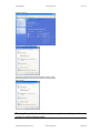
To edit the mouse pointer speed
1. From the “Start” menu choose “Control Panel” and then click on
“Printers and Other Hardware”.
©Unique Perspectives Ltd.
www.click2go.ie
Page 48
User Manual
Genie Joystick
Nov 07
2. Click on “Mouse”.
3. Click on the “Pointer Options” tab.
4. Select the required pointer speed by adjusting the “Motion” slider.
Note that changing the “Enhance pointer precision” option also effects
mouse speed.
Warning: If any of the checks fail contact your supplier immediately and do not
continue to use the Genie joystick.
©Unique Perspectives Ltd.
www.click2go.ie
Page 49
User Manual
4
Genie Joystick
Nov 07
Programming the Genie Joystick
Warning !!
Incorrect or inappropriate programming of the Genie Joystick can put the
wheelchair into a dangerous state. Unique Perspectives accept no responsibility
or liability for accidents caused by incorrect programming. This section must be
read and understood before attempting to program the Genie Joystick
Ensure that the programmed Genie Joystick complies with all prevailing
regulatory requirements for your country and application
Introduction
The performance of the Genie Joystick, its operating mode and parameter
settings may not be decided or known until the chair is supplied to the end user
by their assessment center or other supplier. Typically the fine tuning of the
Genie Joystick will be carried out by a technician in collaboration with an
occupational therapist during assessment of a users operation capability, very
often in the user’s home or place of work. It is for this reason that the
programming of the Genie Joystick’s performance is carried out on the device
itself without the need for a DX hand held programmer or a DX Wizard program.
The Genie Joystick has a set of programmable parameters which allow a
technician in collaboration with an occupational therapist or other professional to
adjust the Genie Joystick so that it best suits a user’s needs and switch/joystick
operation capability. The programmable parameters are described below.
Programmable Parameters Page 1
Selection_Method
This parameter selects the required selection method, i.e. how the user changes
modes.
Selection Method = 1, Switch Only.
Selection Method = 2, Switch + Joystick. (Default)
Selection Method = 3, Joystick + Switch
Selection Method = 4, Joystick Only.
“Switch Only”
By pressing and holding switch 1 the display toggles through symbols representing each mode.
Release switch 1 when the desired mode is displayed.
“Switch + Joystick”
Press switch 1 to enter mode selection. The display shows a symbol representing the first mode.
Deflecting the joystick forward goes onto the symbol for the next mode. Deflecting the joystick
©Unique Perspectives Ltd.
www.click2go.ie
Page 50
User Manual
Genie Joystick
Nov 07
backwards goes onto the symbol or the previous mode. Pressing switch 1 selects the mode that
is displayed.
“Joystick + Switch”
Press switch 1 to enter mode selection. The display shows a symbol representing the first mode.
Pressing switch 1 again goes on to the symbol for the next mode. Deflecting the joystick forward
selects the mode that is displayed.
“Joystick only”
A backwards flick of the joystick selects mode selection. The display shows a symbol
representing the first mode. Deflecting the joystick forward goes onto the symbol for the next
mode. A backwards flick of the joystick selects the mode that is displayed.
Time_Base
This parameter sets the time base for the various selection methods.
In “Switch Only” it is the length of time that the switch must be held in order to move on to the
next mode.
In “Joystick + Switch” it is the repeat rate when the joystick is held forward or backwards.
In “Joystick only” it is the joystick repeat rate but more importantly the length of time that defines
a joystick “flick” is half this time base parameter.
When the accidental hit parameter is set to 2 or 4 the time base defines the
switch acceptance time.
The parameter can be set to one of eight values:1 = time base of 250ms (¼ second)
2 = time base of 300ms
3 = time base of 350ms
4 = time base of 450ms (Default)
5 = time base of 600ms
6 = time base of 800ms
7 = time base of 1.2seconds
8 = time base of 2seconds
Avoid_Accidental_Hits
1 = none
2 = Mode selection
3 = On power up only
4 = Both
Power Up
When set to 3 or 4 this parameter requires a user to hold switch 1 for 2 seconds
before the Genie Joystick will fully power up.
Mode Selection
When set to 2 or 4 switch 1 must be pressed for a certain amount of time before
a switch press is recognised. By setting this option involuntary presses of the
switch can be avoided.
©Unique Perspectives Ltd.
www.click2go.ie
Page 51
User Manual
Genie Joystick
Nov 07
The length of time is half the time base. In other-words if the time base is 1.2
seconds the switch ‘acceptance time’ is 0.6 seconds.
Switch 2
The function for Switch 2 in mouse mode is set according to the following table:
1 – Right Click function (default)
2 – Left Double Click function
3 – Left Drag Lock function
4 – Mouse Speed
5 – Direct exit back to drive mode
When set to 4, the right button can be used to toggle between 3 mouse speeds:
Speed 1
Speed 2
- slow speed
- a combination of slow and fast speeds whereby the mouse starts
off slow and after 1 ½ seconds changes to fast speed.
Speed 3 - fast speed
The new speed is displayed as the right button is pressed. The last speed
setting chosen by the user is stored when the Genie is turned off. When the
Genie is turned on again it will use the stored mouse speed. The default speed
is fast (after a reset). The base mouse speed for an RJM joystick can be
selected with the RJM_Mouse_Speed parameter on program page 3.
Tip!! If the user wishes to use Speed 2 but wants Button 2 to be the right click
then enter program mode and set Button 2 to be the Mouse Speed, exit program
mode and select Speed 2, then re-enter program mode and set Button 2 back to
be the Right Click.
NOTE: In Joystick Only mode it is only possible to use Button 2 for Mouse
Speed or Direct Exit (i.e. option 4 or 5).
Power_Down_Timer
When set to “Y” the Genie will automatically power down after 20 minutes if no
activity is detected.
Exit_Time
The length of time that Switch 1 must be held on order to return to driving mode
from Computer Access mode or External Access mode. In all other modes
pressing switch 1 immediately returns to driving.
1 = 500 ms, 2 = 1 sec,
5 = 4 sec,
6 = 5 sec,
©Unique Perspectives Ltd.
3 = 2 sec,
7 = 6 sec
4 = 3 sec,
8 = 7 sec
www.click2go.ie
Page 52
User Manual
Genie Joystick
Nov 07
It is important to consider whether you are controlling an environmental control
device in external access when setting this parameter. If so remember that
some functions may require switch 1 to be held for a reasonable length of time,
such as a TV volume UP command. It is for this reason that this parameter
exists. Set the Exit_Time long in this type of setup. If you are not connecting an
environmental control then it is better to keep the Exit_Time as short as possible
in order to return to driving as quickly as possible.
Programmable Parameters Page 2
Alarm
This parameter defines what kind of alarm will be made. To activate the alarm
the user must press and hold Switch 1 until an ‘A’ is displayed in the 7 segment
display and the Genie starts beeping rapidly. This length of time is equal to twice
the Exit_Time.
1 – No alarm
2 – Audible alarm
3 – Audible alarm + Text Message
When set to 3 and the Genie is equipped with a BlueTooth interface and the
SmartPhone is switched on and connected the Genie instructs the SmartPhone
to send a pre-written text message is sent to a specific number. For more
information see the “ClickToPhone” user manual.
Max_Profile_Number
This parameter defines the range of Drive profile numbers that the user can
select on the Genie joystick. Note that the Max Profile Number parameter in the
DX wizard file should always be set to 5. See page 63 for programming DX
parameters.
RJM
When set allows a DX remote joystick module to be used as well as the Genie
joystick. Since you can only drive from one joystick at a time you must also set
the “Joystick Source” parameter in the DX wizard to “Remote” for each Drive
Profile in which you wish to drive using the RJM. For menu selection to work
correctly from the RJM one of these profiles must be Drive Profile 1.
There are 3 restrictions when using an RJM Joystick:
1. Mouse movements are non-proportional and only operate in 8 directions.
(The base mouse speed for an RJM joystick can be selected with the
RJM_Mouse_Speed parameter on program page 3)
©Unique Perspectives Ltd.
www.click2go.ie
Page 53
User Manual
Genie Joystick
Nov 07
2. The Joystick Threshold parameter is fixed at 50%.
3. It takes a little longer to switch between operation modes.
NOTE: If you want mouse movements using the Genie joystick to be nonproportional set the Joystick_Threshold parameter to 50% (see next page).
Enable_My_Set
The Genie joystick offers the unique possibility of creating your own set of
operation modes to choose from and in what order you choose them. For
example one user may only want to switch between driving and computer
access whist another may wish to switch between driving, computer access,
seat function and drive profile selection. How to create this set is described later
in this chapter.
After creating your set of operation modes you must enable it by setting this
parameter to ‘Y’.
The default set of operation modes and the order in which they are presented is:
1. Computer Access
2. External Access
3. Seat control
4. Lights,
5. Select drive profile,
6. Power down.
Joystick_Threshold
In non-driving modes the joystick can be thought of as a 4 way switch.
Deflecting the joystick forward is one switch, deflecting the joystick left is
another and so on. The distance away from center that the joystick has to be
deflected before the movement is detected as a switch is called the joystick
threshold.
The joystick threshold also controls the mouse sensitivity. When set to fine a
very small deflection of the joystick will start the mouse moving. When set to
coarse a very large deflection of the joystick is required.
Value
1
2
3
Switch Detect %
12.5%
25% (default)
50%
Mouse sensitivity
Fine
Standard
Coarse (almost non-proportional)
Set this value to 3 if the user is prone to involuntary movements. Set this value
to 1 if the user can make small deflections on the joystick.
©Unique Perspectives Ltd.
www.click2go.ie
Page 54
User Manual
Genie Joystick
Nov 07
Note !! This parameter does not apply to an RJM joystick. The Threshold for
RJM joysticks is fixed at 50%.
External Device
This parameter selects what type of external device you are connected to. It is
specifically to designed to overcome the peculiarities of interfacing to a DynaVox
communication device and to provide a more user friendly interface to a GEWA
Progress ECU.
1 = standard device, such as GEWA Prog3, CAM3, TASH Relax, Tellus, and
any device that can already be controlled using switches.
2 = 2 cable connection to a DynaVox communication device
3 = 2 cable connection to a GEWA Progress
DynaVox communication aids
These devices have 2 switch inputs with isolated common signals. Because the
Genie joystick uses a shared common on the switch outputs it is necessary to
use a special interface cable and to enable this parameter. See page 38 for
wiring details on the interface cable.
Programmable Parameters Page 3
This is a new page of parameters added in Revision C to allow the seat function
list to be edited so that only those actuators which are present on the wheelchair
will be displayed. It allows you to associate a symbol with a particular actuator or
to not display it. The last parameter in this page determines the mouse speed
for RJM joysticks.
The standard seat function list is illustrated below:
Parameter
1
Parameter /
Symbol Name
Back Rest
2
Back Tilt
2
3
Seat Height
5
©Unique Perspectives Ltd.
Symbol
www.click2go.ie
Actuator
(default)
1
Page 55
User Manual
Genie Joystick
Nov 07
4
Foot Rest Left
3
5
Foot Rest Right
4
Back_Rest
This parameter selects which Actuator is associated with the
symbol. Setting
the parameter to 6 means that it will not be displayed in the scan. Default is
Actuator 1.
Back_Tilt
This parameter selects which Actuator is associated with the symbol. Setting
the parameter to 6 means that it will not be displayed in the scan. Default is
Actuator 2.
Seat_Height
This parameter selects which Actuator is associated with the symbol. Setting
the parameter to 6 means that it will not be displayed in the scan. Default is
Actuator 5.
Foot_Rest_Left
This parameter selects which Actuator is associated with the
symbol. Setting
the parameter to 6 means that it will not be displayed in the scan. Default is
Actuator 3.
Foot_Rest_Right
This parameter selects which Actuator is associated with the symbol. Setting
the parameter to 6 means that it will not be displayed in the scan. Default is
Actuator 4.
RJM_Mouse_Speed
This parameter selects the base mouse speed when using an RJM joystick.
1 = slow (default)
2 = medium
3 = fast
©Unique Perspectives Ltd.
www.click2go.ie
Page 56
User Manual
Genie Joystick
Nov 07
Programming Mode
All programmable parameters can be adjusted on the Genie Joystick itself
without the need for a DX hand held programmer or a DX Wizard program.
To select the Programming Mode
1.
Located at the front of the Genie Joystick is a small hole through which
you have access to the programming switch.
2.
Connect the Genie Joystick to a DX system.
3.
Turn on the Genie Joystick by pressing Switch 1.
4.
Press and release the programming switch using a pencil or other suitable
non-metallic object.
LED meaning in program mode.
The parameters are divided into 4 separate groups or ‘pages’.
Page 1 is identified by 1 flash of the decimal point in the 7 segment display. To
move on to the next page press Switch 2.
Page 2 is identified by 2 flashes of the decimal point. To move on to the next
page press Switch 2.
Page 3 is identified by 3 flashes of the decimal point. To move on to the next
page press Switch 2.
Page 4 is identified by 4 flashes of the decimal point.
To exit program mode press Switch 2 one more time. The decimal point flashes
rapidly to indicate the end of program mode and the saving of all parameters
after which normal operation continues.
The battery LEDs of the Genie Joystick are used to indicate which parameter
within a particular page is being adjusted. There are six parameters in each
page and the current parameter is identified by the number of illuminated battery
LEDs. The exception is page 4 which does not use the battery gauge and is for
creating your own set of operation modes. This is discussed further on.
The 7-segment display indicates the value of a particular parameter. The
parameter can be a number or a ‘Y’ or ‘N’ symbol.
©Unique Perspectives Ltd.
www.click2go.ie
Page 57
User Manual
Genie Joystick
7-segment display
indicates value of
parameter.
Nov 07
Number of battery
LEDs indicates
parameter.
Number of flashes of
the decimal point
indicates the current
page.
Selecting a parameter
Switch 1 is used to step from one parameter to the next and to change a
parameter value. A short click of Switch 1 selects the next parameter.
Changing a parameter value
To change the value of a parameter press and hold Switch 1 until the Genie
joystick emits a beep and the parameter value changes.
Tip: Before you enter program mode, look at the table of parameters and know
beforehand what changes you want to make. Photocopy the ‘Quick Reference
Guide’ at the end of this manual and by circling the options you have chosen
you will have a record of your personalised settings.
The tables on the following pages list the Genie Joystick parameters.
©Unique Perspectives Ltd.
www.click2go.ie
Page 58
User Manual
Genie Joystick
Nov 07
Parameter Adjustment Table – Page One
Parameter (page 1)
Selection_Method
Genie
Value and meaning
1
2
3
4
=
=
=
=
Switch Only
Switch + Joystick
Joystick + Switch
Joystick Only
Default: Switch + Joystick
Time_Base
1
2
3
4
5
6
7
8
= 250ms,
= 300ms,
= 350ms,
= 450ms, (Default)
= 600ms,
= 800ms,
= 1.2sec,
= 2 sec
Avoid_Accidental_Hits
1 = No accidental hits are not
avoided (default)
2 = Yes, during mode
selection.
3 = Yes, during startup
4 = Yes, both
Default: No
1
2
3
4
5
Switch 2
= Right Click
= Left Double Click
= Left Drag Lock
= Mouse Speed
= Exit mouse mode
Default: 1 Right Click
4&5 only in Joystick Only mode
N = not required
Y = yes, power down the
Genie after 20mins of no use.
Power_Down_Timer
Default: Yes
1
2
3
4
5
6
7
8
Exit_Time
©Unique Perspectives Ltd.
www.click2go.ie
= 500ms
= 1 sec exit time
= 2 sec (default)
= 3 sec exit time
= 4 sec exit time
= 5 sec exit time
= 6 sec exit time
= 7 sec exit time
Page 59
User Manual
Genie Joystick
Nov 07
Parameter Adjustment Table – Page Two
Parameter (page 2)
Alarm
Genie
Value and meaning
1 = No Alarm
2 = Audible Alarm
3 = Audible Alarm + Text
Message
Default: 1, no alarm
Can be set from 1-5.
Max_Profile_Number
Default: 5
N = not fitted
Y = yes, RJM is fitted
RJM
Default: not fitted.
N = No, do not use my set of
operation modes
Y = yes, use my set of
operation modes.
Enable_My_Set
Default: No
1 = 12.5%, Fine
2 = 25%, Default
3 = 50%, Coarse
Joystick_Threshold
Default: 25%
Does not apply to RJM joystick
(fixed at 50%).
1 = Standard connection.
2 = 2 cable connection to a
DynaVox communication aid.
3 = 2 cable connection to a
GEWA Progress ECU
External_Device
Default: 1
©Unique Perspectives Ltd.
www.click2go.ie
Page 60
User Manual
Genie Joystick
Nov 07
Parameter Adjustment Table – Page Three
Parameter (page 2)
Back_Rest
Genie
Value and meaning
Can be set from 1-6. A setting
between 1 and 5 selects the
physical actuator associated
with this symbol. Setting to 6
disables this symbol from the
seat function display.
Default: 1
Can be set from 1-6. A setting
between 1 and 5 selects the
physical actuator associated
with this symbol. Setting to 6
disables this symbol from the
seat function display.
Back_Tilt
Default: 2
Can be set from 1-6. A setting
between 1 and 5 selects the
physical actuator associated
with this symbol. Setting to 6
disables this symbol from the
seat function display.
Seat Height
Default: 5
Can be set from 1-6. A setting
between 1 and 5 selects the
physical actuator associated
with this symbol. Setting to 6
disables this symbol from the
seat function display.
Foot_Rest_Left
Default: 3
Can be set from 1-6. A setting
between 1 and 5 selects the
physical actuator associated
with this symbol. Setting to 6
disables this symbol from the
seat function display.
Foot_Rest_Right
Default: 4
Sets the base mouse speed
when using an RJM joystick.
1 = Slow
2 = Medium
3 = Fast
RJM_Mouse_Speed
Default: 1
©Unique Perspectives Ltd.
www.click2go.ie
Page 61
User Manual
Genie Joystick
Nov 07
Creating Your Own Set of Operation Modes
With the Genie it is possible to choose not only what operation modes will be
accessible for a particular user but also in what order the will be presented.
The Genie Joystick program page 4 allows the technician to create a unique set
of operation modes.
To create your own set of modes
1. Select page 4 within the program mode (4 flashes of the decimal point)
2. The symbol in the 7 segment display indicates the current “first” mode.
3. Use short clicks of switch 1 to display the “first” mode you want.
4. When it is displayed press and hold switch 1 until the Genie beeps. The
chosen mode for this step is stored and a new step begins.
5. Repeat from step 3 until you have entered all the steps of your set. Note
that you can not exceed 6 steps, i.e. no more than 6 modes anyway.
6. When you have finished entering your set press and release switch 2. The
steps are stored in the Genie Joystick and normal operation resumes.
7. To enable your set you must re-enter program mode and change the
parameter ‘Enable_My_Set’ from ‘N’ to ‘Y’.
Note:
? When you store the first step of a new set the previous set is erased. In
other-words you cannot edit a set, just replace it.
Resetting Parameters to Factory Values
At some stage you may want to reset all the parameters to the factory values.
The factory values are those listed as the default values in the parameter
adjustment tables.
To reset the parameters to factory values
1. Make sure the Genie Joystick is on.
2. Make sure the Genie Joystick is not in program mode.
©Unique Perspectives Ltd.
www.click2go.ie
Page 62
User Manual
Genie Joystick
Nov 07
3. Press and hold the program switch until the decimal point in the 7
segment display begins to flash rapidly, about 4 seconds, then release the
program switch.
4. All parameters have been reset to their factory (default) values.
Note: Be absolutely sure about resetting a user’s parameter settings. If you have
not written them down somewhere there is ‘no way back’.
©Unique Perspectives Ltd.
www.click2go.ie
Page 63
User Manual
5
Genie Joystick
Nov 07
Programming the DX System
Note !!
The Genie Joystick is a third party product manufactured by Unique
Perspectives Ltd. The Genie Joystick contains a DX User Control Module (UCM)
whose programming is loosely based on the DX Dolphin remote. The following
documentation applies to the Genie Joystick and has been referenced from the
DX Dolphin Remote manual.
This section only deals with programming the DX system for optimum
wheelchair performance. For programming of the Genie Joystick operation refer
to chapter 4 in this section.
Warning !!
Incorrect or inappropriate programming of the DX System can put the wheelchair
into a dangerous state. Unique Perspectives accept no responsibility or liability
for accidents caused by incorrect programming. This section must be read and
understood before attempting to program the DX System
Ensure that the programmed DX System complies with all prevailing regulatory
requirements for your country and application
Downloading the correct DX wizard file
Note: Normally it is not necessary to carry out this task as it will already have
been done by your supplier.
Every master remote contains a DX wizard file that specifies all the data
required to safely operate the wheelchair in question. It is not possible to use a
handset (or Genie) from one type of wheelchair on another without first
downloading the correct wizard file. For example a handset fitted to a Cruiser
Plus will not drive a Storm and visa versa.
When you order a Genie specify the type of wheelchair that you are connecting
it to and the Genie will be provided with the correct file already downloaded.
If you have already purchased a Genie or wish to use one on another type of
wheelchair contact [email protected] and we will email you the correct file if
available.
If the correct file is not available there are 2 possible procedures for creating it
and these are explained in the following pages.
©Unique Perspectives Ltd.
www.click2go.ie
Page 64
User Manual
Genie Joystick
Nov 07
Procedure 1: Copying the file from the original handset into the
Genie and editing it (Preferred).
Upload the wizard file from the existing Handset
1. Connect the DX Wizard dongle into the printer port and connect the DX
serial cable from the serial port of your computer and insert it into the
programming socket on the Handset. Turn on the handset.
2. Open the DX wizard program and choose “Read Wheelchair” from the
“Wheelchair” option in the menu bar.
Edit the wizard file with Genie specific options
3. Double click on “UCM Remote” in the program modules list.
4. Ensure that the following 7 parameters are set according to the table below:
Parameter
Max Profile Number
Wrap Profiles
Change Prof Driving
Allow Non Driv Prof
Joystick Actuator
Sleep Enable
Lock Enable
Value
5
Yes
Yes
Yes
Yes
No
No
Download the edited wizard file to the Genie
5. Replace the existing handset with the Genie and connect the DX serial cable
to the programming socket underneath the unit.
6.
Turn on the Genie and download the edited file by choosing “Write
Wheelchair” from the “Wheelchair” option in the menu bar.
7.
After download is complete turn off and on the Genie to complete the
process and confirm that the Genie is driving the wheelchair and that items
can be selected from the menu.
NOTE 1: You must have a Wizard program with OEM options in order to edit the
above parameters. If you do not email your wizard file to [email protected] and
we will do the changes for you.
NOTE 2: If the original handset has a Rev A or older UCM module you will be
prompted to convert the file to a Rev C version when you try to download it to
the Genie. In this instance we recommend you use procedure 2 below or
contact [email protected] and we will do the conversion for you.
©Unique Perspectives Ltd.
www.click2go.ie
Page 65
User Manual
Genie Joystick
Nov 07
Procedure 2: Editing the file in the Genie to match the original
handset
Upload the wizard file from the existing Handset
1. Connect the DX Wizard dongle into the printer port and connect the DX
serial cable from the serial port of your computer and insert it into the
programming socket on the Handset. Turn on the handset.
2. Open the DX wizard program and choose “Read Wheelchair” from the
“Wheelchair” option in the menu bar.
3. Print out the wizard file.
Upload the wizard file from the Genie and edit it
4. Connect the DX serial cable from the serial port of your computer and insert
it into the programming socket on the Genie. Turn on the Genie.
5. Open the DX wizard program and choose “Read Wheelchair” from the
“Wheelchair” option in the menu bar.
6. Double click on “Power Module” in the program modules list. Edit all the
parameters to match those on the print out.
7. Double click on “UCM Remote” in the program modules list. Edit all the
parameters to match those on the print out except those listed in the table
below which should already be set to the values shown.
Parameter
Max Profile Number
Wrap Profiles
Change Prof Driving
Allow Non Driv Prof
Joystick Actuator
Sleep Enable
Lock Enable
Value
5
Yes
Yes
Yes
Yes
No
No
8.
Turn on the Genie and download the edited file by choosing “Write
Wheelchair” from the “Wheelchair” option in the menu bar.
9.
After download is complete turn off and on the Genie to complete the
process and confirm that the Genie is driving the wheelchair and that items
can be selected from the menu.
NOTE 1: You must have a Wizard program with OEM options in order to edit the
above parameters. If you do not email your wizard file to [email protected] and
we will do the changes for you.
©Unique Perspectives Ltd.
www.click2go.ie
Page 66
User Manual
Genie Joystick
Nov 07
Programming Methods & Tools
Dynamic Wizard
The Wizard is a PC based tool suited to programming production runs of
identical wheelchairs or modules, or individual highly customised wheelchairs.
The Wizard is available from Dynamic Controls in several versions:
OEM
Generally used by the wheelchair manufacturer. Able to
program a wide range of parameters
DEALER
Similar in function to above, but with a reduced range of
programmable options. This ensures that options that the
manufacturer wishes to keep control of cannot be
disturbed. Parameters that may cause hazards or require
special expertise to be set are not available to adjust.
ENHANCED
DEALER
As above but with ability to edit parameters that relate
directly to wheelchair accessories (e.g. actuators)
FACTORY
Can only replace Standard or Custom Wheelchair
programs. No editing or diagnostics available.
Warning: The Wizard is a very powerful tool and as such requires well trained
operators and a disciplined approach to usage and distribution
The DX Wizard Manual should be read and understood before attempting to use
it.
Hand Held Programmer (HHP)
The DX Hand Held Programmer (HHP) is the normal programming tool used by
dealers, allowing easy adjustment of all commonly adjusted Drive Program
parameters.
Warning: The DX HHP is for use only by wheelchair manufacturers, their
authorised dealers and support personnel. It is not for use by the wheelchair
user.
The DX HHP manual should be read and understood before attempting to use it.
©Unique Perspectives Ltd.
www.click2go.ie
Page 67
User Manual
Genie Joystick
Nov 07
Auto Download – replacing other modules
The DX System has a feature called Auto Download. It is designed to minimise
the programming requirements associated with Module servicing by down
loading the correct programming to a replacement DX Module.
Auto Download is achieved by DX remotes containing both their own
programming and also a backup copy of the programmed data for all other DX
Modules in the system. When a module is swapped, or a check sum error found
in a module, the DX Remote automatically down loads its backup copy to the
module. The Auto down load occurs immediately on power up after the module
has been replaced. This applies to all DX modules except a DX master remote.
I.e. When you replace a Genie Joystick it will need re-programmimg.
Warning!!
When a Genie Joystick is replaced it will perform an Auto Down load to all DX
modules. This may result in incorrect and dangerous programming for a
particular wheelchair system if the wheelchair program installed in the Genie
Joystick is not suitable for that wheelchair system.
Do not attempt to drive or test the DX system before the correct and suitable
wheelchair program has been installed in the Genie Joystick using the Wizard.
See page 63 “Downloading the correct DX wizard file”.
After replacing any DX Module, turn the DX System off, then on again, to initiate
the Auto down load of the DX Remote backup data. When a Auto Down load
has occurred the status LED of the replaced module will flash. Turn the system
off and them on again to clear this fault and complete the Auto Down load.
©Unique Perspectives Ltd.
www.click2go.ie
Page 68
User Manual
6
Genie Joystick
Nov 07
Battery Warnings, Diagnostics and Fault Finding
Battery Condition Warnings
A battery warning is shown by the battery gauge flashing its LEDs.
Battery high warning condition
This condition occurs when the battery voltage exceeds 28V, as measured by
the PM. The cause can be:
?
?
?
The wheelchair is still on charge and the batteries are full or faulty
The batteries are overcharged
The wheelchair is travelling down a slope and the batteries are full or faulty
The wheelchair will drive during this fault condition which will reset automatically
when the battery voltage drops below 28v.
Battery Low warning condition
This condition occurs when the battery voltage drops below 23.3V, when the
wheelchair is still.
The cause can be:
?
If the battery gauge flashes with orange or green LEDs lit, but the
cause is not due to a battery high fault, the battery or battery wiring
may be faulty.
?
If the battery gauge flashes with just the 1 or 2 red LEDs lit after
stopping the chair, the battery may be too small for the wheelchair
type, or the battery may be old or damaged.
A battery low warning normally coincides with a low capacity warning.
Low capacity warning condition
When the calculated available battery capacity drops below 10% of full capacity
the bottom red LED flashes.
The wheelchair will drive during this fault condition but it shows that the battery
is in the reserve capacity range and battery capacity will begin to reduce very
©Unique Perspectives Ltd.
www.click2go.ie
Page 69
User Manual
Genie Joystick
Nov 07
rapidly. The low capacity warning will not stop until the batteries have been
recharged adequately.
Diagnostics and Fault Finding
DX System diagnostics can be examined from two platforms : from the Flash
Codes signaled with the system status LED on the Genie Joystick (and on the
HHP and from the Wizard which can provide more detailed information about
the fault.
Flash Code
Any fault condition on the DX system will cause the Genie Joystick’s system
status LED to flash. Flashing occurs in burst of flashes separated by a two
second pause. The number of flashes in each burst is referred to as the Flash
Code and indicates the nature of the fault. The title of the Flash Code fault is
also displayed by the HHP if connected to the faulty wheelchair.
Faults that affect the safety of the chair will cause the chair to stop while less
critical ones will be indicated but allow the chair to continue driving. Some faults
will automatically clear when the fault condition is removed, in which case the
System Status LED will extinguish. Other faults are latched and must be cleared
by turning the DX System off, waiting for two seconds, and then turning it back
on again.
DX System
Status LED
Flash Code
Likely cause of condition and possible action
1
DX Module Fault (see limp Mode below)
Cause
An auto download has occurred
Action
? Turn the Genie Joystick off then on again.
Cause
The DX System is not correctly programmed.
Action
? Try reprogramming the DX System
Cause
Connection between DX Modules may be faulty, or
there may be an internal fault in a Module.
Action
? Check DXBUS connections and replace if
necessary
? If the Status LED on another Module is flashing,
replace the Module
? An expected module may not be present (e.g. the
Actuator Module)
2
DX Accessory Fault
©Unique Perspectives Ltd.
www.click2go.ie
Page 70
User Manual
Genie Joystick
Cause
Action
Nov 07
There is a fault in an accessory device attached to a
DX Module (excluding the PM). Examples of faults in
accessory devices may be: the clutch is, or has
been, disengaged; a light bulb is short or open
circuit; an actuator terminal is shorted to Battery +
? Check all accessory devices connected to your
DX System
3
Left (M1) Motor Fault
Cause
The connection from the PM Left (M1) connector to
its associated motor, or the motor itself, is defective.
The connection is either open or short circuit.
Action
? Disconnect the left motor plug and check
continuity between the motor pins on M1
4
Right (M2) Motor Fault
Cause
The connection from the PM Right (M2) connector to
its associated motor, or the motor itself, is defective.
The connection is either open or short circuit.
Action
? Disconnect the right motor plug and check
continuity between the motor pins on M2
5
Left (M1) Park Brake Fault
Cause
The M1 plug connection to its associated park brake
is either open or short circuit
Action
? Disconnect the M1 plug and check continuity
between the two positronic park brake pins
6
Right (M2) Park Brake Fault
Cause
The M2 plug connection to its associated park brake
is either open or short circuit
Action
? Disconnect the M2 plug and check continuity
between the two positronic park brake pins
7
Low Battery Fault
Cause
The battery charge is not sufficient to allow safe
driving. It has fallen below 17V
Action
? Check the battery connection and terminals. The
battery voltage should be similar when the
battery is on charge, and when it isn’t.
? Check that fuses have not blown, or circuit
breakers tripped.
? Replace battery if worn out or if capacity is
insufficient for the user’s needs.
©Unique Perspectives Ltd.
www.click2go.ie
Page 71
User Manual
Genie Joystick
Nov 07
Note: The wheelchair will behave sluggishly and the Battery
Gauge will flash indicating low battery voltage prior to this fault.
8
Overvoltage Fault
Cause
The battery voltage has exceeded 32V
Action
? If this fault occurs during battery charging, the
battery charger is defective or incorrectly
adjusted.
? Check the battery chargers open circuit voltage is
in accordance with the battery manufacturers
limits, and is less than 32V
Cause
The battery connector is making intermittent contact
when the wheelchair is stopped, or travelling down a
slope.
Action
? Check that the battery wiring and terminating is
secure.
9
CANL Fault (see limp mode)
Cause
1. An invalid voltage has been detected on the
DXBUS CANL line.
2. Communication is not possible using the CANL
wire.
Action
? Check the continuity of the DXBUS cable
? Check for shorts between the DXBUS pins. An
open or short circuit on another DX Module can
cause this fault.
10
CANH Fault (see limp mode)
Cause
1. An invalid voltage has been detected on the
DXBUS CANH line.
2. Communication is not possible using the CANH
wire, or the CANJ and CANL wires are shorted
together.
3. Hazard lights were turned on when the DX
system was turned on.
4. The CANH is used to generate a Kill signal by
any DX Module which detects and unsafe
condition, or by an external device such as an
emergency stop switch. The CANH wire is pulled
to either Battery + or Battery – and causes the
DX System to shut down.
©Unique Perspectives Ltd.
www.click2go.ie
Page 72
User Manual
Genie Joystick
Action
11
? Check continuity of the DXBUS cable.
? Check for shorts between the DXBUS pins. An
open or short circuit on another DX Modules can
cause this fault.
? If the hazard lights were already switched on
when the DX system was turned on, Flash code
10 and limp Mode may result. To clear this fault,
turn the Hazard lights off, then turn the DX
System off then on again.
? If generated by a Kill signal, the cause of the fault
is severe.
Stall Timeout Fault
Cause
Action
12
Module Mismatch
Cause
Action
Cause
Action
Nov 07
The motor current has been at, or
close to, current limit for longer than
the Stall Timeout parameter value.
? Turn the DX System off then on
again.
There is a compatibility problem
between DX Modules in the system.
The wheelchair will be disabled.
? Consult your Dynamic service
center.
The data held by the DX UCM for
another DX Module is corrupt or
incompatible with that module
? Reprogramming the wheelchair
system may correct this problem.
Limp Mode
If the DX System detects some faults, it will revert to Limp Mode. This is a
reduced speed mode which recognises problems, but allows the wheelchair
user to limp home, where the problem can be assessed.
©Unique Perspectives Ltd.
www.click2go.ie
Page 73
User Manual
7
Genie Joystick
Nov 07
Maintenance
1. The Genie Joystick system should be regularly checked for integrity. Loose,
damaged or corroded connectors or terminals, or damaged cabling should
be reported to your Service Centre and be replaced immediately.
2. The cabling of Genie Joystick System including Switch cables, DXBUS
cable, Charger cable and Battery cables, should be regularly checked for
integrity. They should never be loose. Cables should be neatly attached to
the wheelchair frame and mounts so that no possibility exists for a cable to
become snagged on the moving parts of the wheelchair itself, the person
sitting in the wheelchair, and/or items external to the wheelchair such as
door handles etc.
3. All switches connected to the Genie Joystick should be regularly tested to
ensure that they function correctly.
4. During storage and transport of your wheelchair ensure that there is no
possibility that Switch 1 can inadvertently by pressed thereby causing the
chair to turn on and possible enter a drive state. Always disengage the motor
gears and disconnect any external switches.
5. Under no condition should a latching switch be connected to the Genie
Joystick. Only connect non-latching switches.
6. The Genie Joystick components and other wheelchair parts should be kept
free of dust, dirt and liquids. If necessary wipe with a cloth dampened with
warm water or alcohol. Do not use solvents or abrasive cleaners.
7. Where any doubt exists, consult your nearest Service Centre or Agent.
8. There are no user-serviceable parts within the Genie Joystick. Do not
attempt to open the case.
9. In accordance with the requirements of CE marking of this device and the
Company’s policy, it is requested that re-occurring faults or defects are
reported back to Unique Perspectives Ltd.
Warning !! If the Genie Joystick is damaged in any way, or if internal damage
may have occurred (for example by being dropped), have it checked by qualified
personnel before operating.
©Unique Perspectives Ltd.
www.click2go.ie
Page 74
User Manual
8
Genie Joystick
Nov 07
Safety and Misuse Warnings
Do not install, maintain or operate this equipment without reading,
understanding and following the proper instructions and manuals, otherwise
injury or damage may result.
The completed installation must be thoroughly checked, and all programmable
options must be correctly adjusted for safe operation prior to use.
A warning must be conveyed to the wheelchair operator that the controller could
cause the chair to come to a sudden stop. In situations where this may affect the
safety of the user, this will require the fitting and wearing of a seat belt.
Performance adjustments should only be made by professionals of the health
care field or persons fully conversant with this process and the driver’s
capabilities. Incorrect settings could cause injury to the driver, bystanders,
damage to the chair and surrounding property.
After the wheelchair has been set up, check to make sure that the wheelchair
performs to the specifications entered in the programming procedures. If the
wheelchair does not perform to specifications, turn the wheelchair off
immediately and re-program. Repeat procedure until the wheelchair performs to
the specifications.
Do not operate the DX system if it behaves erratically, or shows abnormal
response, heating, smoke or arcing. Turn the system off, disconnect the battery
or open the battery overload switch, and consult your service agent.
Do not operate your DX system if the battery is nearly flat as a dangerous
situation may result due to a loss of power in an inopportune place.
Ensure the controller is turned off when not in use.
No connector pins should be touched, as contamination or damage due to
electrostatic discharge may result. Dummy sockets in unused DXBUS
connectors should be left in place unless a new module is added to the system.
Whilst designed to resist water penetration, under certain conditions moisture
might enter the Genie Joystick. Any spillage’s over the Genie Joystick should be
wiped dry without delay. The Genie Joystick may be used outdoors in light
drizzle conditions but should be protected from rain.
Most electronic equipment is influenced by Radio Frequency Interference (RFI).
Caution should be exercised with regard to the use of portable communications
equipment in the area around such equipment. While the manufacturer has
©Unique Perspectives Ltd.
www.click2go.ie
Page 75
User Manual
Genie Joystick
Nov 07
made every effort to ensure that RFI does not cause problems, very strong
signals could still cause a problem. If RFI causes erratic behavior, shut the
wheelchair off immediately. Leave off while transmission is in progress.
In the event of a fault indicator flashing while driving (battery gauge and/or
status LED), the user must ensure that the system is behaving normally. If not,
the system must be turned off and a Service Agent called immediately.
Report any malfunctions immediately to your Service Agent.
Know the risks and limitations
Like any mechanical propelled vehicle there are certain risks involved.
The driver is responsible for any damage or injury that may occur to a party as a
result of using a powered wheelchair. If the driver cannot assume responsibility
due to age or disability then a carer must be present and be able to take over
control either using a stop switch or a dual control in case of an emergency. You
may wish to consider taking out insurance to cover any claims arising from such
an incident.
The most sensitive part of a Genie Joystick system is the joystick element itself.
The owner or carer must assume responsibility for regularly checking the
integrity of the joystick element and report any problems to the service agent
immediately.
©Unique Perspectives Ltd.
www.click2go.ie
Page 76
User Manual
9
Genie Joystick
Nov 07
EC Declaration Of Conformity
Rationale
The Unique Perspectives Ltd. Genie Joystick device is designed for the
intended purpose of providing an alternative method of controlling the function of
a powered wheelchair. A wheelchair is considered a medical device as defined
within Council Directive 93/42/EEC concerning medical devices.
The Genie Joystick is designed for use in combination with a Controls Dynamic
DX control system, incorporates a DX UCM and uses a standard DXBUS
connector.
The Genie Joystick replaces the standard Controls Dynamic’s Joystick.
As the intended purpose is to control a powered wheelchair, and as the Genie
Joystick meets the definition of an “Accessory” of a medical device, as defined
at Article 1 paragraph 2 b) of the Directive, the Genie Joystick has been CE
marked as a medical device in accord with the Directive requirements.
Classification
The Unique Perspectives Ltd. Genie Joystick control system is intended to
provide an alternative operating / control system for those who would find it
difficult, painful, or impossible, due to an injury or handicap, to operate a
standard powered wheelchair control. It is intended to be used in combination
with Class I medical devices only.
The Genie Joystick is classified as a Class I device.
Compliance Certificate
The compliance certificate issued by Unique Perspectives Ltd. does not relieve
a wheelchair manufacturer from compliance testing their particular wheelchairs.
A manufacturers wheelchair must meet the requirements of the directive before
fitting of the Unique Perspectives Ltd. Genie Joystick.
As the Genie Joystick is an ‘Accessory’ to a medical device re-testing of a
manufacturer’s wheelchair with the Genie Joystick fitted is not a requirement.
©Unique Perspectives Ltd.
www.click2go.ie
Page 77
User Manual
Genie Joystick
Nov 07
Council Directive 93/42/EEC of 14 June 1993
concerning medical devices.
Unique Perspectives Limited, Ballyclovan Cottage, Ballyline, Callan, Co. Kilkenny,
Ireland, declare that:
? the Unique Perspectives Limited Genie Joystick device, as described within the
technical file TF.1, conforms to Class I requirements of Council Directive 93/42/EEC
of 14 June 1993 concerning medical devices;
? is in conformity with the provisions of that Directive and, where such is the case,
with the national standards transposing harmonized standards as noted within the
technical file TF 1;
? the requirements of Annex I, Annex VII, Annex IX have been followed for Class I
devices and registration requirements of Article 14 have been notified to the
Rep. of Ireland Competent Authority;
? the Unique Perspectives Limited Genie Joystick device is an Accessory of a medical
device;
? the Declaration covers all Unique Perspectives Limited Genie Joystick devices placed
on the market on or after May 2003 and until such time as a renewed conformity
declaration is raised.
This declaration is signed on behalf of Unique Perspectives Limited by:
Signed
Name
Company Position
Date
©Unique Perspectives Ltd.
www.click2go.ie
May 2003
Page 78
User Manual
10
Genie Joystick
Nov 07
Warranty
All equipment supplied by Unique Perspectives Ltd is warranted by the company
to be free from faulty materials or workmanship. If any defect is found within the
warranty period of 6 months, the company will repair the equipment, or at its
discretion, replace the equipment without charge for materials and labor.
The warranty is subject to the conditions that the equipment:
?
Has been correctly installed
?
Has been used solely in accordance with this manual.
?
Has been properly connected to a DX Power Module in accordance with this
manual.
?
Has not been subjected to misuse or accident, or been modified or repaired
by any person other than someone authorised by Unique Perspectives Ltd.
?
Has been used solely for the driving of electrically powered wheelchairs in
accordance with the wheelchair manufacturer’s recommendations.
©Unique Perspectives Ltd.
www.click2go.ie
Page 79
User Manual
11
Genie Joystick
Nov 07
Sales and Service Information
For Sales and Service advice, or in case of any difficulty, please contact:
Unique Perspectives Ltd.
Ballyclovan
Callan
Kilkenny
Ireland
Telephone:
Fax:
+353 56 7725913
+353 56 7725936
www.click2go.ie
[email protected]
Note: The controller should be clearly labeled with the manufacturer’s service
agent’s telephone number.
©Unique Perspectives Ltd.
www.click2go.ie
Page 80
User Manual
12
Genie Joystick
Nov 07
Genie Joystick Quick Reference Guide
Page 1 Parameters
Selection_Method
Value and meaning
1
2
3
4
=
=
=
=
Switch Only
Switch + Joystick
Joystick + Switch
Joystick Only
Page 2 Parameters
Alarm
Value and meaning
1 = No Alarm
2 = Audible Alarm
3 = Audible Alarm + Text
Message
Default: 1, no alarm
Default: 2 Switch + Joystick
Time_Base
Avoid_Accidental_Hits
Switch 2
1 = 250ms,
2 = 300ms,
3 = 350ms,
4 = 450ms, (Default)
5 = 600ms,
6 = 800ms,
7 = 1.2sec,
8 = 2 sec
1 = No accidental hits are not
avoided (default)
2 = Yes, during mode
selection.
3 = Yes, during startup
4 = Yes, both
Max_Profile_Number
1
2
3
4
5
Enable_My_Set
= Right Click
= Left Double Click
= Left Drag Lock
= Mouse Speed
= Exit mouse mode
Can be set from 1-5.
Default: 5
RJM
N = not fitted
Y = yes, RJM is fitted
Default: not fitted.
N = No, do not use my set of
operation modes
Y = yes, use my set of
operation modes.
Default: No
Default: 1 Right Click
Power_Down_Timer
N = not required
Y = yes, power down the
Genie after 20mins of no use.
Joystick_Threshold
Default: Yes
Exit_Time
1
2
3
4
5
6
7
8
=
=
=
=
=
=
=
=
500ms
1 sec exit time
2 sec (default)
3 sec exit time
4 sec exit time
5 sec exit time
6 sec exit time
7 sec exit time
Also effects mouse movement
sensitivity (see text)
Does not apply to RJM joystick
(fixed at 50%)
External_Device
1 = Standard connection.
2 = 2 cable connection to a
DynaVox communication aid.
3 = 2 cable connection to a
GEWA Progress ECU
Default: 1
To set a parameter
1.
Make sure the Genie Joystick is on.
2.
Select program mode by pressing the program switch.
3.
Page 1 is automatically selected.
4.
The number of times the decimal point flashes indicates what page you are on. To select the
next page press switch 2.
5.
Select the parameter by clicking switch 1 until the corresponding number of battery LEDs are
lit.
6.
Change the parameter by holding down switch 1 until the unit beeps and the value displayed in
the 7 segment display changes.
7.
To exit program mode step through the remaining page(s) by clicking Switch 2 until the decimal
point flashes very rapidly.
To reset the parameters to factory values
1.
Make sure the Genie Joystick is on.
2.
Press and hold the program switch for about 3 seconds until the decimal point flashes rapidly,
then release the program switch.
3.
All parameters have been reset to their factory (default) values.
Before you do any programming, look at the these tables of parameters and know beforehand what
changes you want to make. Be absolutely sure about changing a user’s parameter settings. It is a
good idea to photocopy this sheet and make note of a user’s parameter settings.
©Unique Perspectives Ltd.
1 = 12.5%
2 = 25%
3 = 50%
Default: 25%
www.click2go.ie
To modify the seat function list
1.
Enter program mode and select page 3.
2.
The first five parameters determine what actuator is
controlled by what seat symbol.
3.
Change a parameter in the normal way (see opposite
text). Each parameter can be set from 1 to 6. Setting a
parameter to 6 means that seat symbol will not be
used.
4.
See text for further explanation.
To create your own set of operation modes
5.
Enter program mode and select page 4.
6.
The symbol in the 7 segment display indicates the first
mode.
7.
Use short clicks of Switch 1 to select the mode you
want for this step.
8.
When it is displayed press the primary switch for a long
time, until the Genie beeps. The chosen mode for this
step is stored and a new step begins.
9.
Repeat from step 3 until you have entered all the steps
of your set. Note that you can not exceed 6 steps.
10.
When you have finished entering your set press and
release switch 2. The steps are stored in the ClickToGo
and normal operation resumes.
11.
To enable your set you must re-enter program mode
and change the parameter ‘Enable_Set’ on page 2 from
‘N’ to ‘Y’.
Page 81
IMPROVEMENTS TO GENIE JOYSTICK
16/12/03
From unit number 31 the following functionality has been added:
1.
It is now possible to program Button 2 to be either
Right Click,
Left Double Click,
Left Drag Lock,
(new)
Mouse Speed
(new)
Go back to Drive mode. (new)
2.
(new)
When set to Mouse Speed Button 2 selects 1 of 3 mouse speeds. Previously the Genie had just one speed (slow
speed).
Speed 1 is a slow speed.
Speed 2 is a combination of slow and fast speed whereby the mouse starts off slow and after 1 ½ seconds increases
to fast speed.
Speed 3 is a fast speed.
It is possible to adjust the speed setting for the fast speed using the Windows control panel.
It is not possible to adjust the speed setting for the slow speed using the Windows control panel (as before).
The mouse speed is stored when the unit is turned off.
3.
In external mode, Button 2 is used to go back to Drive Mode (before it switched the Genie off)
7/6/05
From unit number 51 the following functionality has been added:
REVB
1.
It is now possible to operate the Genie Joystick and RJM at the same time in all modes except driving. It is still
necessary to set the RJM parameter to Yes in the Genie as well as enabling the RJM in the DX Wizard program.
2.
Mouse movements have been improved and it is now possible to select between Fine, Standard and Course
sensitivities. This is achieved when setting the joystick threshold parameter – see text. Requires mouse emulators with
serial numbers greater than 40.
21/11/05
From unit number 59 the following functionality has been added:
1.
2.
3.
4.
5.
6.
REVC
It is now possible edit the seat function list so that a seat function symbol can be associated with a particular actuator.
Furthermore it is possible to disable a seat function symbol from the list. This means that if a chair is fitted with only 2
actuators for example, then only the 2 appropriate seat function symbols will be displayed when seat function mode is
enabled.
To facilitate the above a forth program page has been added to the parameter list. To aid programming the selected
program page is now indicated by the number of times the decimal point flashes.
Seat function mode has also been improved in that left/right deflections will not select the next/previous actuator unless
the joystick is neutral. This prevents inadvertent selections of the next/previous actuator.
Mouse speed has been increased and the default set to fast.
It is now possible to interface to the GEWA Progress ECU so that operation is more intuitive. The Progress must be set
for 2 switch manual row/column scanning. When external access is selected downward deflections select the row. A
right hand deflection selects the cell in that row. Finally another downward deflection activates the chosen cell. External
access can be exited at anytime by pressing switch 1.
A USB interface cable is now available. This allows the Genie to be connected to the USB port of an “on-chair”
computer or communication device. The cable connects from the Genie switch output port to the USB port of the
external device. The cable has electronics built in which “fool” the computer or communication device into thinking that a
standard USB mouse is connected. When external access is selected the joystick on the Genie is used to move the
mouse pointer and button 1 makes left click selections. Note that this interface is in addition to the wireless mouse
already built into the Genie. This means that the user can have wireless control over a desktop computer, and also
control (through the cable) of an “on-chair” computer.
28/2/06
From unit number 61 the following functionality has been added:
1.
2.
REVD
It is now possible to fit a bluetooth module internally within the Genie. This allows the Genie to control a SmartPhone. A
new menu item “t” appears in the menu. When selected the Genie is controlling the SmartPhone. The SmartPhone
must be equipped with BlueTooth and be running Windows Mobile 2003. See the “ClickToPhone” user manual for
further details.
It is now possible to generate an alarm. By holding Switch 1 for twice the Exit Time an audible and Text message alarm
are generated.