1
page 2
Index
1
2
3
4
4
4
5
5
5
5
6
6
7
7
7
7
7
7
7
8
8
8
8
9
10
10
11
11
11
11
12
12
12
13
13
13
14
14
14
15
15
16
17
18
19
19
20
20
21
21
21
21
22
23
23
23
24
24
General instructions
Index
0 - Handbook layout
1 - Studio 24 Scan Control console layout
1.1 - Main features
1.2 - Technical specifications
1.3 - Studio 24 Scan Control’s sections
1.3.1 - Manual Presets
1.3.2 - Registers
1.3.3 - Light Chase Controls
1.3.4 - Masters
1.3.5 - DMX Unit Controls
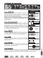
1.4 - Studio 24 connectors
1.4.1 - DMX 512
1.4.2 - Up-Down pedal
1.4.3 - SMPTE
1.4.4 - Midi
1.4.5 - RS-232
1.4.6 - Audio In
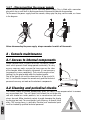
1.4.7 - Disconnecting the power supply
2 - Console maintenance
2.1 - Access to internal components
2.2 - Cleaning and periodical checks
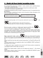
3 - Studio 24 Scan Control operating modes
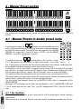
4 - Manual Presets section
4.1 - Manual Presets in double preset mode
4.1.1 - Go function
4.1.2 - Solo function
4.1.3 - Link function
4.2 - Manual Presets in single preset mode
4.1.1 - Go function
4.1.2 - Solo function
4.1.3 - Link function
5 - Registers section
5.1 - Memory pages
5.2 - Register operating modes
5.3 - Storing a scene
5.4 - Modify a stored scene
5.5 - Copying a stored scene to another scene
6 - Light Chase Controls section
6.1 - Chase running
6.2 - Creating and modifying chases
7 - DMX Unit Controls section
7.1 - Direct mode use
7.1.1 - Program elements
7.2 - Groups of units
7.3 - Movement effects
7.4 - Use in Reg mode
7.5 - The Utilities
7.5.1 - Remote lamp ignition
7.5.2 - Remote fixture reset
7.5.3 - Operating areas
7.6 - Creating a program
7.6.1 - Copying a scene
7.6.2 - Copying a program
7.6.3 - Adding a Program to a Memory Register
8 - Setup functions
8.1 - Addressing light channels
24
24
25
25
26
26
26
26
27
28
28
29
30
30
31
31
32
33
35
35
35
36
36
36
36
37
37
37
38
38
38
38
38
38
38
39
39
39
39
40
40
40
41
42
42
45
46
47
50
51
8.1.1 - Equalization curves
8.2 - Addressing the fixtures
8.3 - Changing the language used
8.4 - Available memory
8.5 - Built-in memory
8.5.1 - Creationg a new unit
8.5.1.1 - DMX channel total
8.5.1.2 - LCD effect labels
8.5.1.3 - Internal addressing
8.5.1.4 - Standby values
8.5.1.5 - Type of effect
8.5.1.6 - Mirror/Head
8.5.1.7 - Slope Speed
8.5.1.8 - Unit name
8.5.1.9 - Remote and lamp reset values
8.5.1.10 - Dip-switch configuration
8.5.1.11 - Beam search values
8.5.1.12 - Type of control
8.5.2 - Error messages
8.5.3 - Modifying a unit in the library
8.5.4 - Deleting a unit from the library
9 - Using the connectors
9.1 - Pedal
9.2 - SMPTE socket
9.3 - Midi connectors
9.3.1 - Midi In - Note On
9.3.2 - Midi In - Note Off
9.3.3 - Midi In - Program Change
9.3.4 - Midi In - All Channels Off
9.3.5 - Midi In - Bank Select
9.3.6 - Midi Out - Program Change
9.3.7 - Midi Out - Bank Select
9.4 - RS-232 connections
9.4.1 - RS-232 - Channel On (01h)
9.4.2 - RS-232 - Channel Off (A2h)
9.4.3 - RS-232 - All Off (A3h)
9.4.4 - RS-232 - Register Change (A0h)
9.4.5 - RS-232 - Page Change (A4h)
9.4.6 - RS-232 - Device Select (A6h)
10 - Using ‘Event Recording’
10.1 - ‘Event Recording’ operating modes
10.2 - Creating a track
10.3 - Replaying a track
11 - Advanced use of the Studio 24 Scan Control
11.1 - Multiple units
11.2 - Multiple scanner units
11.3 - Using the colourchangers in pseudo-random mode
12 - Quick Reference
12.1 - Tree structure diagram of Setup functions
13 - Practical users guide