1
www.conairgroup.com
USER GUIDE
UGD039-0313
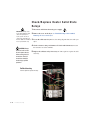
SlimLine
Compressed Air Dryer
Models 2.5, 5, 15, 25 and 50
SL50
SL25
SL5
SL2.5
SL15
Corporate Office: 412.312.6000 l Instant Access 24/7 (Parts and Service): 800.458.1960 l Parts and Service: 814.437.6861
Please record your equipment’s
model and serial number(s) and
the date you received it in the
spaces provided.
It’s a good idea to record the model and serial number(s) of your equipment and
the date you received it in the User Guide. Our service department uses this information, along with the manual number, to provide help for the specific equipment
you installed.
Please keep this User Guide and all manuals, engineering prints and parts lists
together for documentation of your equipment.
Date:
Manual Number: UGD039-0313
Serial Number(s):
Model Number(s):
DISCLAIMER: The Conair Group, Inc., shall not be liable for errors contained in this User Guide or
for incidental, consequential damages in connection with the furnishing, performance or use of
this information. Conair makes no warranty of any kind with regard to this information, including,
but not limited to the implied warranties of merchantability and fitness for a particular purpose.
Copyright 2013 l The Conair Group l All rights reserved
Ta b l e o f C o n t e n t s
1-1 I n t r o d u c t i o n
Purpose of the user guide . . . . . . . . . . . . . . . . . . . . . . . . . . . . . . . . 1-2
How the guide is organized . . . . . . . . . . . . . . . . . . . . . . . . . . . . . . 1-2
Your responsibilities as a user . . . . . . . . . . . . . . . . . . . . . . . . . . . . . 1-3
ATTENTION: Read this so no one gets hurt . . . . . . . . . . . . . . . . . . . 1-4
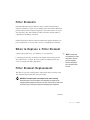
2-1 D e s c r i p t i o n
What is the SlimLine - Compressed Air Dryer?. . . . . . . . . . . . . . . . .2-2
Typical applications . . . . . . . . . . . . . . . . . . . . . . . . . . . . . . . . . . . . .2-2
How it works: The SlimLine . . . . . . . . . . . . . . . . . . . . . . . . . . . . . . .2-3
How it works: Typical Plant Compressed Air System. . . . . . . . . . . . .2-4
Specifications: SlimLine . . . . . . . . . . . . . . . . . . . . . . . . . . . . . . . . . 2-5
Application data: SlimLine . . . . . . . . . . . . . . . . . . . . . . . . . . . . . . . . 2-5
3-1 I n s t a l l a t i o n
Unpacking the boxes . . . . . . . . . . . . . . . . . . . . . . . . . . . . . . . . . . . 3-2
Preparing for installation . . . . . . . . . . . . . . . . . . . . . . . . . . . . . . . . . 3-3
Lifting the dryer (models SL25 and 50) . . . . . . . . . . . . . . . . . . . . . . 3-4
Mounting the hopper/dryer unit. . . . . . . . . . . . . . . . . . . . . . . . . . . . 3-5
Mounting a loader onto the hopper . . . . . . . . . . . . . . . . . . . . . . . . . 3-6
Mounting a hand-fill lid (optional) on models SL15, SL25, SL50 . . . 3-7
Connecting the main power . . . . . . . . . . . . . . . . . . . . . . . . . . . . . . 3-7
Connecting a compressed air supply. . . . . . . . . . . . . . . . . . . . . . . . 3-8
Ta b l e o f C o n t e n t s l i
4-1 O p e r a t i o n
The SlimLine control panel . . . . . . . . . . . . . . . . . . . . . . . . . . . . . . . 4-2
Loading material into the hopper. . . . . . . . . . . . . . . . . . . . . . . . . . . 4-3
Adjusting the pressure regulator . . . . . . . . . . . . . . . . . . . . . . . . . . . 4-3
To start drying. . . . . . . . . . . . . . . . . . . . . . . . . . . . . . . . . . . . . . . . . 4-4
To stop drying . . . . . . . . . . . . . . . . . . . . . . . . . . . . . . . . . . . . . . . . . 4-5
Setting the high alarm setpoint . . . . . . . . . . . . . . . . . . . . . . . . . . . . 4-6
Changing the temperature units (fahrenheit/celsius) . . . . . . . . . . . . 4-6
Installing the optional slide gate . . . . . . . . . . . . . . . . . . . . . . . . . . . 4-7
Installing the optional drain valve . . . . . . . . . . . . . . . . . . . . . . . . . . 4-8
Using the optional slide gate . . . . . . . . . . . . . . . . . . . . . . . . . . . . . . 4-9
Using the optional drain valve . . . . . . . . . . . . . . . . . . . . . . . . . . . . 4-10
5-1 M a i n t e n a n c e
Preventative maintenance checklist . . . . . . . . . . . . . . . . . . . . . . . . 5-2
Cleaning the hopper . . . . . . . . . . . . . . . . . . . . . . . . . . . . . . . . . . . . 5-3
Inspecting hoses . . . . . . . . . . . . . . . . . . . . . . . . . . . . . . . . . . . . . . 5-4
6-1 Tr o u b l e s h o o t i n g
Before beginning. . . . . . . . . . . . . . . . . . . . . . . . . . . . . . . . . . . . . . . 6-2
A few words of caution . . . . . . . . . . . . . . . . . . . . . . . . . . . . . . . . . 6-3
DIAGNOSTICS
How to identify the cause of a problem . . . . . . . . . . . . . . . . . . . . . 6-4
Alarms . . . . . . . . . . . . . . . . . . . . . . . . . . . . . . . . . . . . . . . . . . . . . 6-5
REPAIR
Removing the cover on the dryer . . . . . . . . . . . . . . . . . . . . . . . . . . 6-8
Replacing fuses. . . . . . . . . . . . . . . . . . . . . . . . . . . . . . . . . . . . . . . . 6-9
i i l Ta b l e o f C o n t e n t s
Check/Replace heater solid state relays . . . . . . . . . . . . . . . . . . . . 6-10
Checking the heater . . . . . . . . . . . . . . . . . . . . . . . . . . . . . . . . . . . 6-11
Replacing the heater assembly . . . . . . . . . . . . . . . . . . . . . . . . . . . 6-12
Replacing the differential pressure switch. . . . . . . . . . . . . . . . . . . 6-13
A
Appendix
We’re here to help . . . . . . . . . . . . . . . . . . . . . . . . . . . . . . . . . . . . . A-1
How to contact customer service . . . . . . . . . . . . . . . . . . . . . . . . . . A-1
Before you call... . . . . . . . . . . . . . . . . . . . . . . . . . . . . . . . . . . . . . . A-1
Equipment guarantee . . . . . . . . . . . . . . . . . . . . . . . . . . . . . . . . . . A-2
Performance warranty . . . . . . . . . . . . . . . . . . . . . . . . . . . . . . . . . . A-2
Warranty limitations . . . . . . . . . . . . . . . . . . . . . . . . . . . . . . . . . . . . A-2
B
Appendix
Determining airflow in the SlimLine dryer . . . . . . . . . . . . . . . . . . . . B-1
Relating the heater inlet pressure to the airflow . . . . . . . . . . . . . . . B-1
Calculating the airflow through the hopper to specify the mass
of air . . . . . . . . . . . . . . . . . . . . . . . . . . . . . . . . . . . . . . . . . . B-2
C
Appendix
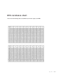
RTD temperature resistance chart. . . . . . . . . . . . . . . . . . . . . . . . . . C-1
D
Appendix
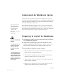
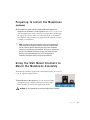
Compressed air membrane option . . . . . . . . . . . . . . . . . . . . . . . . . D-1
Preparing to install the membrane . . . . . . . . . . . . . . . . . . . . . . . . . D-2
Using the wall mount bracket to mount the membrane assembly . . D-2
Mounting the differential pressure gauge to the filterhead . . . . . . . D-3
Ta b l e o f C o n t e n t s l i i i
D
Appendix
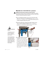
Installing the compressed air piping for membrane
assembly installation . . . . . . . . . . . . . . . . . . . . . . . . . . . . . . D-3
Membrane installation . . . . . . . . . . . . . . . . . . . . . . . . . . . . . . . . . . D-4
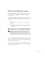
Start-up and operation . . . . . . . . . . . . . . . . . . . . . . . . . . . . . . . . . . D-7
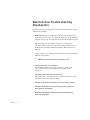
Maintenance and troubleshooting (general). . . . . . . . . . . . . . . . . . . D-8
Maintenance and troubleshooting checkpoints . . . . . . . . . . . . . . . . D-9
Filter elements . . . . . . . . . . . . . . . . . . . . . . . . . . . . . . . . . . . . . . . D-10
When to replace a filter element . . . . . . . . . . . . . . . . . . . . . . . . . . D-10
Filter element replacement . . . . . . . . . . . . . . . . . . . . . . . . . . . . . . D-10
Automatic draining mechanism. . . . . . . . . . . . . . . . . . . . . . . . . . . D-13
Drain provisions . . . . . . . . . . . . . . . . . . . . . . . . . . . . . . . . . . . . . . D-14
i v l Ta b l e o f C o n t e n t s
SECTION
1
Purpose of the user guide . . . . . . . . . . . . . . 1-2
How the guide is organized . . . . . . . . . . . . . 1-2
Yo u r r e s p o n s i b i l i t i e s a s a u s e r . . . . . . . . . . . 1 - 3
AT T E N T I O N :
Read this so no one gets hurt . . . . . . . . 1-4
Introduction l 1-1
1
Introduction
Introduction
Purpose of the User Guide
This User Guide describes the Conair SlimLine Compressed Air Dryer
and explains step-by-step how to install, operate, maintain, and repair this
equipment.
Before installing this product, please take a few moments to read the User
Guide and review the diagrams and safety information in the instruction
packet. You also should review manuals covering associated equipment in
your system. This review won’t take long, and it could save you valuable
installation and operating time later.
How the Guide is Organized
Symbols have been used to help organize the User Guide and call your
attention to important information regarding safe installation and operation.
Symbols within triangles warn of conditions that could be hazardous to users or
could damage equipment. Read and take precautions before proceeding.
1
Numbers indicate tasks or steps to be performed by the user.
◆
A diamond indicates the equipment’s response to an action performed by the user.
❒
An open box marks items in a checklist.
•
A circle marks items in a list.
✒
✐
1-2 l Introduction
Indicates a tip. A tip is used to provide you with a suggestion that will help you with
the maintenance and the operation of this equipment.
Indicates a note. A note is used to provide additional information about the steps
you are following throughout the manual.
Yo u r R e s p o n s i b i l i t y a s a U s e r
• Thorough review of this User Guide, paying particular attention
to hazard warnings, appendices and related diagrams.
• Thorough review of the equipment itself, with careful attention
to voltage sources, intended use and warning labels.
• Thorough review of instruction manuals for associated equipment.
• Step-by-step adherence to instructions outlined in this User Guide.
Introduction l 1-3
1
Introduction
You must be familiar with all safety procedures concerning installation, operation and maintenance of this equipment. Responsible safety procedures include:
AT T E N T I O N :
Read this so no one gets hurt
We design equipment with the user’s safety in mind. You can avoid the potential
hazards identified on this machine by following the procedures outlined below and
elsewhere in the User Guide.
WA R N I N G : I m p r o p e r i n s t a l l a t i o n , o p e r a t i o n , o r
servicing may result in equipment damage or
p e r s o n a l i n j u r y.
This equipment should be installed, adjusted, and serviced by qualified
technical personnel who are familiar with the construction, operation,
and potential hazards of this type of machine.
All wiring, disconnects, and fuses should be installed by qualified electrical technicians in accordance with electrical codes in your region.
Always maintain a safe ground. Do not operate the equipment at power
levels other than what is specified on the machine serial tag and data
plate.
WA R N I N G : Vo l t a g e h a z a r d
This equipment is powered by single-phase alternating current,
as specified on the machine serial tag and data plate.
A properly-sized conductive ground wire from the incoming power
supply must be connected to the chassis ground terminal inside the
electrical enclosure. Improper grounding can result in severe personal
injury and erratic machine operation. (120 Volt units come with a
grounded plug. Must be plugged into a grounded out.)
Always disconnect and lock out the incoming main power source before
opening the electrical enclosure or performing non-standard operating
procedures, such as routine maintenance. Only qualified personnel
should perform troubleshooting procedures that require access to the
electrical enclosure while power is on.
1-4 l Introduction
(continued)
(continued)
Always protect yourself from certain exterior surfaces that can reach temperatures in excess of 200°F {93°C}. These surfaces include the hopper
cone and the exterior of the dryer casting. Also exercise caution around
hot surfaces inside the dryer when cleaning or accessing the inside of the
hopper.
Introduction l 1-5
1
Introduction
CA U T I O N : H o t S u r fa c e s
1-6 l Introduction
SECTION
2
What is the SlimLine Compressed air dryer? . . . . . . . . . . . . . 2-2
Ty p i c a l a p p l i c a t i o n s . . . . . . . . . . . . . . . . . . 2 - 2
How it works: SlimLine . . . . . . . . . . . . . . . . 2-3
H o w i t w o r k s : Ty p i c a l p l a n t c o m p r e s s e d a i r
system . . . . . . . . . . . . . . . . . . . . . 2-4
Specifications: SlimLine . . . . . . . . . . . . . . . 2-5
Description l 2-1
2
Description
Description
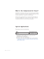
What is the Compressed Air Dryer?
The SlimLine is an integral dryer and hopper used to dry hygroscopic resin pellets.
The dryer uses compressed air in an open loop configuration and heats the air with
an electric resistance heater to dry pellets located in the hopper.
The dryer must be supplied with clean, dry compressed air supplied at 40° F {4°
C} dewpoint and 100 psi with a oil content of less than 3 mg/m3 to produce hot,
low dewpoint air that removes moisture from hygroscopic plastic.
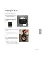
Ty p i c a l A p p l i c a t i o n s
1 Dryer/hopper mounted on the machine throat.
Model
Drying Temperature Range
Standard
100° - 350°F {38° - 177°C}
• Throughput rates of 0.25 to 50 lbs {0.12 to 23 kg} per hour (some
materials can be run at a higher rate).
• Dewpoints of 0°F {-18°C} (standard dryer)
• Dewpoints of -40°F {-40°C} (dryer equipped with an optional membrane)
See Appendix D for instructions for installing, operating and troubleshooting the
optional membrane assembly.
2-2 l Description
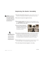
H o w I t Wo r k s : T h e S l i m L i n e
The SlimLine Compressed Air Dryer achieves continuous, single pass drying by
expanding compressed air and then passing the air through a heater(s) and injecting it into the hopper.
Material In
1
Isolation Valve
From Plant Distribution System
2
1
✐
Clean, dry air is expanded to low pressure during the process of passing through the air regulator. Expanding the air
reduces the dewpoint.
The regulator is also
used to adjust the air
flow to the green range
on the (air) pressure regulator.
3
Filter
Filter
Membrane
3
the SlimLine standard dryer.
Then, the air is injected
into the hopper where it
passes over the pellets
and reduces the final
moisture content of the
plastic material to
acceptable processing
levels.
See Appendix D for instructions for
installing, operating and troubleshoot ing the optional membrane assembly.
The air exhausts from the
hopper into the atmosphere.
Note: The membrane is sold as an option to
Material Out
* This drawing is used to facilitate the understanding of how the dryer works and is not an actual representation of your
dryer. For example, the compressed air is plumbed on the opposite side on the dryer you purchased.
Description l 2-3
2
Pressure Gauge
{
Optional Membrane
Description
2
Air Out
Next, the air passes
through an electric heater
where its’ temperature is
raised to the process setpoint temperature.
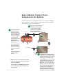
H o w I t Wo r k s : Ty p i c a l P l a n t
Compressed Air System
Pre-dried compressed air at a specification of 40° F {4° C} dewpoint and 100 psi
with a maximum oil content of 3 mg/m3 is obtained with a properly sized typical
plant compressed air system as shown below.
2
1
The typical plant-sized
compressor draws in
ambient air and compresses it to 100 - 150
psi {6.9 - 10.3 bar}. A
compressor compresses air by applying
mechanical force. Heat
is generated as a
byproduct of the compression cycle.
Ambient Air In
Next, the air passes through an
aftercooler that helps to lower
the temperature of air, this
reduces both the moisture in
the air and condensation in the
the compressed air lines.
2
Filter
1
Aftercooler
Receiver
To Drain
Filter
As air passes through
the receiver it cools,
reducing the dewpoint
and the temperature of
the air.
To Drain
To Plant Distribution System
3
Refrigerated Air Conditioner
Filter
Some water will collect
and drain from the
receiver.
Filters: Filters are recommended for protecting
the devices downstream from their location from
moisture, oil and/or dirt.
There should also be low point traps with automatic drains to allow trapped condensation to
leave the system.
2-4 l Description
To Drain
3
A refrigerated air conditioner (RAC) is
installed in the compressed air system
before the air enters the plant’s distribution system. This system evaporates refrigerant at ~ 34° F {1° C} and
serves to cool the compressed air to
about 40° F {4° C}, hence the dewpoint to 40° F {4° C}. The air leaving
the RAC is significantly warmer than
40° F {4° C} because the leaving air is
passed through an economizer to
reduce the energy consumption and
prevent condensation on the air pipes
leaving the refrigerated air conditioner.
Specifications: SlimLine
Compressed Air Dryers
This portion of
the hopper only
on Model
SL50
{
This portion of
the hopper only
on Model
SL50
{
compressed
air inlet
compressed
air inlet
B
C
B
C
Front View
Side View
Front View
Side View
Models SL2.5
and SL5
Models SL2.5
and SL5
Model SL15*, 25 and 50
Model SL15*, 25 and 50
MODEL
SL2.5
SL5
SL15*
SL25
SL50
Performance characteristics (with full hopper)
Drying temperature
All models 100 - 350°F {38 - 176°C}
Dewpoint
0°F {-18°C} with optional membrane - 40°F {- 40°C}
Airflow SCFM {SLM}
2.5 {70.8}
5 {141.6}
7.5 {212.4} 12.5 {354.0}
25.0 {708.0}
Airflow with membrane SCFM {SLM}
3.1 {88.0}
6.8 {193.0}
9.3 {263.0} 15.7 {445.0}
34.9 {988.3}
Hopper volume ft3 {L}
0.125 {3.5}
0.25 {7.1}
0.75 {21.2} 1.25 {35.4}
2.5 {71.0}
Heater size kW
1
1
1
2
2
Dimensions inches {cm}
A - Height
22.5 {57.2} 40.0 {101.6} 26.5 {67.3} 32.0 {81.3}
47.5 {120.7}
B - Overall width
11.0 {27.9}
11.0 {27.9}
12.5 {31.8} 15.5 {39.4}
15.5 {39.4}
C- Depth
19.0 {48.3}
19.0 {48.3}
25.5 {64.8} 24.0 {61.0}
24.0 {61.0}
Drying hopper inlet pipe size
1/2 NPT female
Weight lbs {kg}
Standard dryer installed (empty)
32 {14.5}
37 {17}
56 {25)
87 {39}
107 {49}
Shipping
60 {27.2}
70 {31.8}
160 {72.6} 160 {72.6}
160 {72.6}
Voltage - Total amps
120 V/1phase/60 Hz
8.5
8.5
8.5
16.7
16.7
220 V/1 phase/50 Hz
4.3
4.3
4.3
8.4
8.4
Compressed air requirements†
100 PSI, clean dry compressed air pressure
dewpoint of 40°F {5°C} ; residual oil content of less than 3 mg/m3
SPECIFICATION
NOTES:
SCFM - Standard Cubic
Feet per Minute
SLM - Standard Liters
per Minute
* Model SL15 does not
include a access door on
the hopper.
†
Compressed air supplied
to the dryer must meet
specification requirement
of 100 psi and 40°F
{4°C} dewpoint and a
residual oil content of
less than 3mg/m3 .
Specifications may change
without notice. Consult a
Conair representative for
the most current information.
APPLICATION NOTES:
Conair recommends purchasing the optional membrane when:
● your process requires that you obtain a dewpoint of -40°F {- 40°C}; or the compressed air dewpoint you are suppling is above 40°F {4°C}.
TPDS026-0408
Description l 2-5
2
Description
A
A
Application data: SlimLine
Compressed Air Dryers
1 Identify the resin and throughput rate. Use the chart as a reference for determining your throughput rate.
MODEL THROUGHPUT RATE** / LB/HR
MATERIAL
DRYING
TEMP/°F {°C}†
ABS (0.05%)§ 180-190 {82-88}
Nylon (0.6%)§ 160-180 {71-82}
PET (0.05%)§ 300-350 {144-177}
150 {66}
PETG (0.04%)§
PPS (0.04%)§ 270-300 {132-144}
DRYING
BULK
SL2.5
SL5
SL15
SL25
SL50
2.5
0.4
2.5
0.4
0.4
5
0.8
5
0.8
0.8
15
5
15
5
5
25
8.3
25
8.3
12.5
50
16.6
50
16.6
16.6
TIME/HOUR* DENSITY‡
2
6
2
6
6
40
40
50
40
50
DRYING
BULK
MODEL THROUGHPUT RATE** / LB/HR
MATERIAL
Acetal
Acrylic
PBT
PC
Polysulfone
Polyurethane
PPO
SAN
DRYING
TEMP/°F {°C}†
180-230 {82-110}
170-180 {77-82}
210-260 {99-127}
250 {121}
200-275 {93-135}
180-210 {82-99}
190-230 {88-110}
160-180 {71-82}
SL2.5
SL5
SL15
SL25
SL50
15
15
7.5
15
7.5
NA††
7.5
10
25
25
12.5
25
12.5
16.6
12.5
16.6
50
50
25
50
25
33
16.6
33
TIME/HOUR* DENSITY‡
2
2
4
2
4
3
4
3
40
40
45
40
35
40
50
45
2.5
5
2.5
5
1.3
2.5
2.5
5
1.3
2.5
NA†† NA††
1.3
2.5
1.6
3.3
APPLICATION NOTES:
*
This dryer is not recommended for applications using a high percentage of regrind (]20%).
† The parameters of drying temperature and time may vary depending upon the type, grade and manufacturer of the
material being processed. Consult your material supplier for their precise recommendations.
‡ Unit of measurement for bulk density is lb/ft3. Bulk density listed is the nominal weight for typicalpellets. The bulk
density may vary somewhat depending upon the size and shape of the pellets. The bulk density of regrind may
vary widely depending upon the size and the shape of the flake. Be sure to consider the bulk density of the
material when selecting the capacity of the drying hopper and the drying time desired.
§ Number refers to the residual moisture content by weight of the pellet at the listed throughputs and drying times.
To increase the level of dryness, the throughput of the material would need to be decreased and the drying time
increased.
** Throughputs will vary by type of material. Consult Conair about throughput for materials that are not listed here.
†† Dryer is not recommended for this application due to bridging of material in the smaller hopper opening.
2-6 l Description
SECTION
3
Installation
Unpacking the boxes . . . . . . . . . . . . . . . . . 3-2
Preparing for installation . . . . . . . . . . . . . . 3-3
Mounting the hopper/dryer unit . . . . . . . . . . 3-5
Mounting a loader onto the hopper . . . . . . . . 3-6
Mounting a hand-fill lid (optional) on models
SL15, SL25 and SL50 . . . . . . . . . . . . . . 3-7
Connecting the main power . . . . . . . . . . . . . 3-7
Connecting a compressed air supply . . . . . . . 3-8
Installation l 3-1
3
Installation
Lifting the dryer (models SL 25 and 50) . . . . 3-4
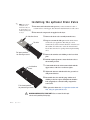
Unpacking the Boxes
The SlimLine dryer comes in one to several boxes, depending on the model and
options ordered. The boxes could include (depends on the options selected):
• Compressed air dryer/hopper
• Hand-fill lid (standard on SL2.5
and SL5; optional on SL15, SL25 and
SL30)
Model SL15
Hopper has a hinged top
plate. Hand-fill lid needed
to cover center hole.
Model SL25
and SL50
• IB06 mounting interface (pre-mounted and standard on SL15, SL25 and SL30)
• Slide gate (option)
• Mounting adapter with drain (option)
• Compressed air membrane (option) See Appendix D for instructions for
installing, operating and troubleshooting the optional membrane assembly.
• User manual and wiring diagrams (not shown)
1 Carefully remove the dryer and components from their shipping containers,
and set upright. Note that the dryer (depending on model ordered) may be
secured to its shipping container with 4 bolts that pass through the bottom of
the mounting flange.
2 Remove all packing material, protective paper, tape, and plastic.
3 Carefully inspect all components to make sure no damage occurred during
shipping, and that you have all the necessary hardware. If damage occurred during shipping notify the shipping agent immediately.
3-2 l Installation
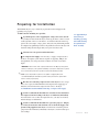
Preparing for Installation
The SlimLine dryer is easy to install if you plan the location and prepare the
mounting area properly.
1 Make sure the mounting area provides:
❒ A grounded power source supplying the voltage and correct current
for your dryer model. Check the dryer’s serial tag (models 2.5 and 5, located
on the right side of the cover; models 15, 25 and 50 on the back of the hopper) for the correct amps, voltage, phase, and cycles. Any field wiring should
be completed by qualified personnel to the planned location for the dryer. All
electrical wiring should comply with your region’s electrical codes.
See Appendix D for
instructions for
installing, operating
and troubleshooting
the optional membrane assembly.
❒ Clearance for safe operation and maintenance.
IMPORTANT: The flow rate of the compressed air must be at 100 psi {6.9 bar} at the
entrance to the dryer (or the optional membrane). If your plant compressed air system,
✐
does not meet this specification you will not achieve desired drying results.
Note: If your compressed air system is not capable of supplying the Conair
recommended dewpoint listed above you will need to purchase the optional membrane to ensure proper drying.
❒ Flex hose for connecting compressed air to the dryer. It is also acceptable to use a rigid, 1/2 inch NPT union and compressed air supply pipe to
make the connection from the compressed air source to the dryer.
See Installation section entitled, Connecting a compressed air supply.
❒ Conair recommends the installation of an isolation valve installed on
the compressed air line leading to the dryer or membrane (if installed).
You will use the valve to shut off compressed air to your dryer for cleanout,
material changes or maintenance.
❒ Conair recommends the installation of a pressure gauge (0 - 160 psi)
{0 - 11 bar} downstream of the isolation valve to check the supply of air
pressure being supplied to the dryer. You will need to install the pressure
gauge before the membrane (if installed) or the dryer to obtain accurate pressure readings.
Installation l 3-3
3
Installation
❒ A compressed air supply. It is necessary to supply compressed air to
the dryer. Your plant system must be capable of supplying 100 psi {6.9
bar}and 40°F {4°C} dewpoint with a residual oil content of less than 3
mg/m3.
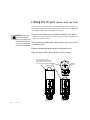
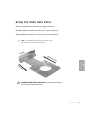
Lifting the Dryers
(Models SL25 and SL50)
For increased safety in lifting Conair recommends that all dryer/hopper units are
lifted without material in the hopper. When using the lifting lugs on models SL25
and SL50 it is required that no material be in the hopper.
CAUTION: Always make
sure the loader adapter
plate is secure on the SL25
and SL50 before lifting the
units. Failure to do so could
result in injury to personnel.
1 Bolt the loader adapter plate (models SL25 and SL50) securely in place.
This secures the lid to the hopper and prevents it from sliding off during installation. See illustration below.
2 Use the lifting lugs (models SL25 and 50) to lift the empty dryer onto the
mounting location.
3 Remove the lifting lugs (SL25 and 50) after mounting the dryer.
4 Reverse the procedure to remove the dryer from the machine.
The screw on top of the
loader adapter plate must be
tightened to secure the lid to
the hopper. (SL25 and SL50)
Top View
Model SL25
Lifting lugs
Lifting lugs
3-4 l Installation
Front View
Front View
Model SL50
Model SL25
Mounting the Hopper/Dryer Unit
2 Bolt the unit to the throat of the processing machine. Using four 3/8”-16 (M
10) self-locking bolts, fasten the hopper/dryer to the throat. The bolts must be
long enough to reach at least 1/2 inch (1.25 cm) into the processing machine
throat or mounting adapter after passing through the hopper discharge assembly.
▲
▲
▲
3 inches
(7.6 cm)
diameter
▲
▲
6 inches
(15.2 cm)
square
▲
3 inches
(7.62 cm)
square
(10.16 cm)
square
standard on models
SL25 and SL50
7/16 inches
(1.11 cm)
diameter
5 inches
(12.7 cm)
square
Installation l 3-5
3
▲ 4 inches
▲
(3.81 cm)
diameter
▲
standard on models
SL2.5, SL5 and
SL15
1.5 inch
Base Plate
IB02
Installation
7/16 inches
(1.11 cm)
diameter
Base Plate
IB01
▲
discharge assembly so that its’ bolt holes line up with the holes drilled in the
throat. If hole patterns do not match, you can place a mounting adapter between
the throat and the support frame.
▲
1 Lift the unit onto the throat of the processing machine. Position the hopper
NOTE: If your mounting
surface does not match
the standard bolt patterns
available, you will need
an adapter. You can make
an adapter using the
dimensions provided or
purchase one from
Conair. Contact Conair
Parts at 1.800.458.1960
From outside the United
States, call 814.437.6861
▲
✐
The hopper bolts to the throat of the processing machine.
Mounting a Loader on a Hopper
Models SL2.5 and SL5 (option)
✒Tip: To prevent
material contamination Conair recommends that the hopper be covered with
a loader or a handfill lid.
If your SL2.5 or SL5 was purchased with the loader fill option, you will need to
mount the TLA loader to the adapter on top of the glass hopper.
1 Position the loader body onto the top of the TLA
adapter. Position the loader assembly so that it fits
snugly on to the top of the TLA mounting adapter located on top of the glass hopper. Tighten the thumbscrews.
2 Supply power to the TLA loader. Refer to the manual
the came with your loader for specific instructions.
3 Supply compressed air to the TLA loader. Refer to
the manual the came with your loader for specific
instructions.
✐ NOTE: The SL2.5 and SL5 units are equipped with a handfill lid as standard. There is an optional mounting loader
adapter and loader available for this unit. To purchase from
Conair. Contact Conair Sales at 1.800.654.6661, from outside the United States, call 412.312.6000
Mounting a Loader on a
Hopper
Models SL15, SL25 and SL50
If you have a Conair loader or vacuum receiver, you can use
the flange provided on the top of the hopper to mount the
loader. Refer to the manual that came with your receiver or
loader for detailed installation instructions.
8-INCH CONAIR LOADER MOUNTING INTERFACE
8.25 in.
(210 mm)
diameter
5/16 in.
(8 mm)
diameter
bolt holes
7.375 in.
(187 mm)
diameter
bolt pattern
3-6 l Installation
Mounting the Hand-fill Lid
Models SL15, SL25 and SL50
✒Tip: To prevent material contamination Conair
recommends that the
hopper be covered with a
Models SL15, SL25 and SL50 come standard with an IB06 mounting interface for
loader fill. If you choose not to use a loader on one of these units, purchase and
install the optional hand-fill lid to prevent material contamination or moisture
regain.
loader or a hand-fill lid.
1 Bolt the hand-fill lid to the top of the hopper.
Use the bolts provided to secure the hand-fill
lid to the top of hopper.
C o n n e c t i n g t h e M a i n Po w e r
The dryer operates from standard 120 Volt, 60 Hz or 220 Volt, 50 Hz depending on
the option selected when purchased.
1 Plug the dryer into a properly sized electrical outlet.
Model - 120 Volt
SL2.5, SL5 and SL15
SL25 and SL50
Model - 220 Volt
All
✐
15A, 120 V
20A, 120 V
15A, 220 V
NOTE: Dryers ordered with 220 Volt will need to be wired to a
disconnect that is protected by properly sized protectors (fuses or
breaker).
CAUTION: Always disconnect and lock out the main power sources
before making electrical connections. Electrical connections should be
made only by qualified personnel.
IMPORTANT: Always refer
to the wiring diagrams that
came with your dryer to
locate specific electrical
components. Illustrations in
the User Guide are intended
to be representative only.
Installation l 3-7
3
Installation
Represents the hand-fill lid for
Models SL25 and SL50.
Connecting a Compressed Air Supply
It is necessary to supply a compressed air supply to the dryer. Your plant system
must be capable of supplying 100 psi {6.9 bar} and 40°F {4°C} dewpoint with a
residual oil content of less than 3mg/m3 specification.
1 Connect compressed air to the 1/2 inch NPT female inlet of
the dryer. You can use a piece of flex hose to make the connection. The hose should be pressure and temperature rated
for this the application. The tubing should be cut to length for
efficiency. It is also acceptable to use a rigid, 1/2 inch NPT
union and compressed air supply pipe to make the connection from the compressed air source to the dryer.
✐
Note: All connections should have an isolation valve and pressure gauge (customer supplied) for verification of pressure. The flow rate of the compressed air must be at 100
psi {6.9 bar} at the entrance to the dryer (or the optional membrane). If your plant
compressed air system, does not meet this specification you will not achieve proper
drying. Since pressure drops occur during flow you must verify that the 100 psi {6.9
bar} specification is met when air is flowing.
IMPORTANT: The compressed air source must deliver 100 psi {6.9 bar} of clean, dry (non-lubricated), air
pressure at the design flow. The air connected to the dryer cannot be lubricated, if it is your material will
become contaminated with the lubrication.
IMPORTANT: You should not use threaded sealant tape on the compressed air connection. Use of these
items can contaminate your compressed air circuit. A quick disconnect fitting may be used to facilitate
easy air line connection and removal for the main supply line, but the fitting should not be the type that
restricts air flow.
2 Confirm a good connection with a gentle tug.
CAUTION: Always provide hazard-free routing of compressed air tubing, to keep it away
from hot or moving surfaces and out of the way of personnel.
3-8 l Installation
SECTION
4
Operation
The SlimLine: control panel. . . . . . . . . . . . . 4-2
Loading material into the hopper . . . . . . . . . 4-3
To s t a r t d r y i n g . . . . . . . . . . . . . . . . . . . . . 4 - 4
To s t o p d r y i n g . . . . . . . . . . . . . . . . . . . . . 4 - 5
Setting the high alarm setpoint . . . . . . . . . . 4-6
Changing the temperature units
(fahrenheit/celsius) . . . . . . . . . . . . . . . . . . 4-6
Installing the optional slide gate . . . . . . . . . 4-7
Installing the optional drain valve . . . . . . . . 4-8
Using the optional slide gate . . . . . . . . . . . . 4-9
Using the optional drain valve . . . . . . . . . . 4-10
Operation l 4-1
4
Operation
Adjusting the pressure regulator . . . . . . . . . 4-3
The SL Series Compressed Air Dryer Control
A c t u a l D r y i n g Te m p e r a t u r e
Shows the (process) actual temperature
value.
Control Codes
See Section 6,
Troubleshooting
for a list of possible causes and
solutions for the
Alarms.
Heater
Status
Indicates the alarm
status. (High
Temperature Alarm
only.)
Indicates the
heater status.
Drying Temperature
Control Codes:
A.hi1
Er.i1
rP1
h.Pr
Alarm
Indication
- High Temp. Alarm
- Input Error
- Ramping Target
- Heater Output (%)
Actual
Alarm
Heater
Startup:
1.
2.
3.
4.
With dryer power off, start airflow.
Adjust airflow to green zone.
Switch on dryer.
Press Run/Reset.
Output 1 - Alarm
Output 2 - Heater
Run/Reset
Shutdown:
Setpoint
1.
2.
3.
4.
Lower setpoint to 70°F (21°C).
Switch off dryer.
Allow to cool 1 minute.
Stop airflow.
SlimLine Resin Dryer
Return Button (green)
Cycles through:
Setpoint Drying
Te m p e r a t u r e
h.Pr - heater percentage (%) on time (read only - can
help with troubleshooting)
Shows the setpoint
temperature value.
A.hi - high temperature alarm setpoint (adjustable
with arrow keys)
Celsius - Fahrenheit - Changes from °F to °C (change
with arrow keys)
Er.i1 - input error
rP1- displays when a new setpoint has been selected
(temporary target temperature)
Note: See Section 6, Troubleshooting, for additional
information.
4-2
l Operation
O N / O F F To g g l e
Switch
Run/Reset
Button
Used to turn the
power on or off.
Used to turn the
power to the heaters
on during power-up
or after an alarm.
IMPORTANT: This is
NOT a main power
disconnect.
Loading Material into the Hopper
1 Use your installed conveying equipment or hand-fill material into the hopper.
✒Tip: If you hand-fill your hopper remember to close the lid to reduce moisture regain
and to keep you material contaminant-free.
Adjusting the Pressure Regulator
1 Turn the knob of the pressure regulator in a
✐
Note: If the regulator does not move easily, pull up on the
knob to unlock it.
2 Adjust the air flow so that the pressure gauge
reads at the top of the green level.
3 Push down on the knob to lock the pressure
gauge at a flow rate in the green area on the
gauge.
CAUTION: DO NOT set the pressure in the red section of the pressure gauge. Damage to
the internal components of the dryer can occur at high pressure.
DO NOT set the pressure in the red
section of the pressure gauge.
Operation l 4-3
4
Operation
clockwise direction to allow increased airflow.
Starting the Dryer
You have completed the installation. Now it’s time to make sure everything
works.
1 Adjust airflow appropriately. See Operation section entitled, Adjusting
the pressure regulator.
2 Toggle the power switch to the on position. The control display will illumiOn Position
nate. Facing the dryer, the (process) actual temperature will be on the left, the
setpoint is on the right.
3 Press the “Run/Reset” button to enable
the heating circuit. The button will
illuminate.
Drying Temperature
Actual
Alarm
Heater
4 Set the drying temperature setpoint. Use
the up arrow button ▲ on the control, to
raise the setpoint. Use the down arrow
button ▼ to lower the setpoint. The temperature will ramp up at 1 (one) degree per
second. After 2 (two) seconds of inactivity
the setpoint you entered will become the
targeted setpoint.
Setpoint
5 The setpoint and actual temperature will show in the display. Facing the
dryer, the (process) actual temperature will be on the left, the setpoint is on
the right.
6 Pre-dry for approximately three hours* before you begin to process
✒Tip: Conair recommends
that you keep the material level within three
inches from the top of
the hopper to allow
enough residence time
for the material to be
properly dry.
4-4
l Operation
material. *Three hours is an estimated pre-drying time, some material may
require a longer or shorter pre-drying time. See Description section entitled,
Application Data.
7 Open the slide gate (optional) and begin processing.
Stopping the Dryer
1 Close the (optional) slide gate.
2 Press the down arrow ▼ to lower
Drying Temperature
the setpoint to 70°F {21°C}.
Actual
Alarm
Heater
3 Toggle the switch to the off position.
Setpoint
Off Position
4 Allow five minutes for the heaters to cool
5 Turn the pressure regulator counterclockwise until the compressed air flow
stops.
✒Tip: To keep material dry without processing let a
little air move through the dryer at an idle setpoint.
✐
NOTE: Moisture regain will be reduced if a
small amount of compressed air is allowed to
pass through the material even with the power
off.
Operation l 4-5
4
Operation
down.
✐
Setting the High Alarm Setpoint
NOTE: Processing is
not affected by this
adjustment.
1 Press the green return button twice.
A.hi will appear on the right side of
the controller as you are facing the
dryer. The setpoint appears on the
left.
Alarm
Heater
Actual
1
2 Press the ▲ or ▼ buttons to select
the high alarm setpoint. The setpoint you choose will depend on the
specific properties of you material.
Your material supplier provides recommendations for proper drying.
✒Tip: See also, Section 6,
Troubleshooting for
3 The infinity button
information on how to
will take you back to the main screen, where you
will see the setpoint and actual temperature displayed. The control will default
back to the main screen after 1 minute.
reset this setpoint if an
A.hi alarm occurs.
CAUTION: The high alarm setpoint should be lowered if the material being processed would be
damaged or melt at the factory default setting of 450°F {232°C}.
CAUTION: DO NOT set the dryer above the default of 450°F {232°C}. The dryer is not rated for temperatures above 450°F {232°C}. Setting it above that temperature could cause damage to the dryer or
your material.
✐
C h a n g i n g Te m p e r a t u r e U n i t s f r o m
Fa h r e n h e i t t o C e l s i u s
NOTE: Processing is
not affected by this
adjustment.
Drying Temperature
Alarm
Heater
Actual
button three (3) times. Press the ▲
or ▼ buttons to toggle between the temperature units of fahrenheit and celsius.
1 Press the green return
2 Press the infinity button
1
4-6
l Operation
to lock in your selection and
return to the main screen where you will see the setpoint and
actual temperature displayed. The control will default back to
the main screen after 1 minute.
3 in.
Installing the optional Slide Gate
Va
✐ lve
NOTE: If you are following this set of instructions and your SL dryer/hopper is not
installed, you may skip to step 3.
1 Disconnect and lockout the main power. If you have mounted a loader or vacuum receiver on the hopper, disconnect the material inlet hose at the source.
2 Disconnect the compressed air supplied to the dryer.
3 in.
Models SL2.5,
5 and 15
9/32
in.
3 Remove the slide gate
4 Prepare to mount the slide
5 in.
Models SL25
and 50
5 Fasten the lower plate (thicker), the nylon spacer and the thin upper plate
in the orientation you selected for your application.
9/32
in.
6 Securely tighten all four fasteners using a thread locking compound and/
or self-locking fasteners.
Models SL25
and 50
7 To operate the slide gate See Operation section entitled, Using the optional slide gate.
Operation l 4-7
4
Operation
gate. Decide which orientation best fits your application.
The slide gate can be mounted in any of the four basic
directions on the throat of the
machine. You will want to
select the orientation that has
the best clearance for opening
and closing the slide gate.
Models SL 2.5,
5 and 15
5 in.
assembly from the boxes.
✐
NOTE: If you are following this set of
instructions and your
SL dryer/hopper is not
installed, you may skip
to step 3.
I n s t a l l i n g t h e o p t i o n a l D r a i n Va l v e
1 Disconnect and lockout the main power. If you have mounted a loader or
vacuum receiver on the hopper, disconnect the material inlet hose at the source.
2 Disconnect the compressed air supplied to the dryer.
On Machine throat
3 Remove the drain valve assembly from the boxes.
4 Prepare to mount the slide gate. Decide which orienta-
To drain
Full open positionfor draining material
tion best fits your application. The slide gate can be
mounted in any of the four basic directions on the throat of
the machine. You will want to select the orientation that
has the best clearance for opening and closing the draining
valve.
5 Remove the stainless steel cladding on the lower slide
plate.
6 Drill the required pattern to fasten the drain valve to
the mounting location.
On Machine
throat
7 Countersink the heads of the fasteners flush with the
upper surface of the lower carbon steel plate.
8 Tighten the fasteners with thread lock to prevent loosening from vibration.
9 Reassemble the valve with 24 gauge stainless steel
cladding on the lower plate and tighten the shoulder
bolts, (supplied) use a thread locking compound to
secure bolts.
Full closed positionfor processing material
10 To operate the drain valve See Operation section entitled, Using the optional drain valve.
WARNING: MOVING PARTS; PINCH POINTS Use care around the drain gate
valve to avoid a possible pinching injury.
4-8
l Operation
U s i n g t h e S l i d e G a t e Va l v e
1 Turn off and disconnect the main power supply to the dryer.
2 Pull the handle toward the front of the dryer to open the slide gate.
3 Push the handle toward the rear of the dryer to close the slide gate.
✐
NOTE: In an intermediate position the material will be shut off
from the throat of the machine and not drained.
e
ndl
Ha
Op
en
Po
siti
on
Cl
os
e
WARNING: MOVING PARTS; PINCH POINTS Use care around the slide gate
valve to avoid a possible pinching injury.
Operation l 4-9
4
Operation
To
U s i n g t h e O p t i o n a l D r a i n Va l v e
The drain valve can be in the processing (open to the processing machine throat),
the standby (closed) or the drain position (over the drain tube).
1 Turn off and disconnect the main power supply to the dryer.
2 Shut the slide valve (optional). This isolates the hopper from the throat of the
machine.
3 Pull the dryer/hopper unit toward the dump chute. To move the drain valve
assembly lift the locking pin and pull the handle to the desired location. Listen
to the locking pin and visually verify that the unit has snapped into place.
WARNING: MOVING
PARTS Use care around
the throat of the processing machine. When the
dryer is pulled off of the
throat of the processing
machine it will expose
dangerous moving components. Keep all body parts
and clothing away from
the machine throat to
avoid serious injury.
4 Connect the black pipe discharge to a piece of 1 1/2 inch flex hose. Direct
the hose into a bucket or some type of receptacle.
5 Open the slide valve (if equipped) and drain the material.
6 Close the slide valve (if equipped).
7 Slide the dryer/hopper unit back into position. Listen to the locking pin and
Processing position
4-10
l Operation
visually verify that the unit has snapped into place. Make sure that personnel
and tools are clear of the processing machine throat, lift the pin and slide the
drain valve over the throat.
✐
NOTE: In an intermediate position the material will be shut off
from the throat of the machine and not drained.
Draining position
SECTION
5
Maintenance
Preventative maintenance checklist . . . . . . . 5-2
Cleaning the hopper. . . . . . . . . . . . . . . . . . 5-3
Inspecting hoses
. . . . . . . . . . . . . . . . . . . 5-4
5
Maintenance
Maintenance l 5-1
Preventative Maintenance
Checklist
Routine maintenance will ensure optimum operation and performance of the
SlimLine Dryer. We recommend the following maintenance schedule and tasks.
• Whenever you change materials
❒ Drain and clean the hopper.
• We e k l y, o r a s o f t e n a s n e e d e d
❒ Check the quality of your compressed air.
You may need to clean filters more often than weekly. Frequency depends
on how much material you process and how dusty or full of fines it is
You should replace any filter if it damaged, excessively worn or too
clogged to be properly cleaned.
• Every six months
❒ Inspect hoses for damage or wear.
Damaged compressed air hose can allow moisture or contamination to
seep into the drying system. Replace any hose that is torn or cracked.
❒ Inspect the installation
Check installed mounting hardware to make sure that the installation is
secure.
❒ Inspect the compressed air system
Check the compressed air system for leaks. Compressed air leaks could
compromise the performance of the SlimLine dryer.
5-2 l Maintenance
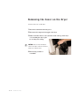
Cleaning the Hopper
CAUTION: Hot surfaces. Always protect yourself from hot surfaces inside and outside the
dryer and drying hopper.
The hopper assembly should be cleaned thoroughly between material changes to prevent
resin contamination.
1 Close the hopper slide gate if the option was purchased on your dryer.
2 Remove the material from the dryer.
3 Wipe the material surfaces. Use a
clean, oil-free rag to wipe the internal
surfaces of the hopper.
5
Maintenance
Maintenance l 5-3
Inspecting Hoses
Loose or damaged hoses can allow moisture regain or material contamination.
Compressed air leaks are also expensive and wasteful.
1 Inspect all hoses, clamps, fittings.
2 Tighten any loose hose clamps or fittings.
3 Replace worn or damaged hoses.
5-4 l Maintenance
SECTION
6
Tr o u b l e s h o o t i n g
Before beginning . . . . . . . . . . . . . . . . . . . . 6-2
A few words of caution
. . . . . . . . . . . . . . 6-3
DIAGNOSTICS
How to identify the cause of a problem . . . . 6-4
Alarms
. . . . . . . . . . . . . . . . . . . . . . . . . 6-5
R E PA I R
Removing the cover on the dryer . . . . . . . . . 6-8
Replacing fuses . . . . . . . . . . . . . . . . . . . . 6-9
Check/Replace heater solid state relays . . . 6-10
Checking the heater . . . . . . . . . . . . . . . . . 6-11
Replacing the differential pressure switch . . 6-13
Maintenance l 6-1
6
Troubleshooting
Replacing the heater assembly . . . . . . . . . 6-12
Before Beginning
You can avoid most problems by following the recommended installation and
maintenance procedures outlined in this User Guide. If you do have a problem,
this section will help you determine what caused it and how to fix it.
❏ Diagnose causes from the control panel.
1
Press
once to acknowledge the alarm and resume control if
required.
2
Address the alarm message and fix the problem.
3
If the alarm reappears the problem was not fixed.
Heater
Output
#1
4. Press
indicates an
alarm condition
1
This green return
button should be
pressed once to
acknowledge a
High Temperature
alarm.
Sh d
✐
❏ If you need to call Conair Service for assistance please note the percent
(%) on time of the heater. It will be important in troubleshooting a
dryer malfunction. Also take note of the setpoint and actual
temperatures, the line pressure and regulator setting.
NOTE: The percent (%) on number can be read from the first menu displayed on the controller, by pressing the green return button one (1) time. This number should only be read
after the unit has had time to stabilize at the setpoint temperature.
(continued)
6 - 2 l Tr o u b l e s h o o t i n g
Before Beginning
(continued)
See warnings
below.
Open the electrical
enclosure to check
fuses and heater
contactors.
✐
Note: Picture only representative
of the dryer. Yours may not look
exactly the same.
❏ Find the wiring and equipment diagrams that were shipped with your dryer. These diagrams are the best reference for correcting a problem. The diagrams also will note any custom
features, such as special wiring or alarm capabilities, not covered in this User Guide.
A Fe w Wo r d s o f C a u t i o n
Improper corrective actions can lead to hazardous conditions and should
never be attempted to sustain production.
WARNING: High voltage. Always stop the SlimLine dryer, disconnect and
lock out the main power source before troubleshooting or performing
repairs.
CAUTION: Hot surfaces. Always protect yourself from hot surfaces inside
and outside of the dryer and hopper.
Tr o u b l e s h o o t i n g l 6 - 3
6
Troubleshooting
WARNING: Only qualified service personnel should examine and correct
problems that require opening the dryer’s electrical enclosure or using
electrical wires to diagnose the cause.
How to Identify the Cause of a
Problem
The High Temperature Alarm is indicated by an illuminated Alarm light on the
SlimLine control panel and an alarm code, A.hi is displayed in the control window.
When an alarm code is displayed on the control:
1 Find the error message in the diagnostics table of this troubleshooting
section and reference the control sticker in the upper left hand side.
2 Note that, after correcting the problem, pressing the Acknowledge Alarm
button will clear the alarm. The alarm will only clear if the condition causing the alarm has been corrected.
Drying Temperature
Alarm
Heater
Actual
Startup:
1.
2.
3.
4.
With dryer p
Adjust airflow
Switch on dr
Press Run/R
1
A.hi alarm
light - high
temperature
Shutdown:
Setpoint
6 - 4 l Tr o u b l e s h o o t i n g
1. Lower setpo
2. Switch off dr
3. Allow to coo
Alarms
A problem can trigger two types of alarms:
• Latching Alarm : If the red Alarm LED is on, the alarm is a shutdown alarm. The dryer has
automatically shut down because it detected a serious problem that could damage your material or
dryer. Note that the Alarm must be acknowledged before the control will resume by pressing the
infinity button.
See also Operation section entitled, Setting the High Temperature Setpoint.
• Cycling Alarm (internal safety devices): The dryer has two internal safety devices to avoid
overheating. A differential pressure switch which senses that there is low or no air flow and shuts the
heater off, and a safety snap switch on the heater, that detects a high heater internal temperature.
Both conditions will shut the heater off until the condition goes away or has been corrected, then the
control resumes. There is no signal to the operator for this condition.
Possible cause
Solution
A.hi (alarm light illuminated) – If the process temperature exceeds the process high
temperature setpoint, it shuts
down the dryer. Default is set
to 450°F (232°C).
One of the process solid state relays has
failed.
Replace the solid state relay. See
Troubleshooting section entitled,
Checking/Replacing Solid State Relays.
The air lines are restricted or loose.
Straighten any crimps in the hoses.
Tighten any loose hoses.
The process setpoint is higher than the
alarm setpoint.
Set the process setpoint higher.
The process output on the control has
failed.
Replace the process controller.
RTD (resistance temperature device) is
not providing acceptable range of resistance.
Plug the RTD into the harness. See the
wiring diagrams shipped with your
machine.
Er.i1 – Input error
✐
Note: See the RTD resistance chart
to determine if the sensor is
bad. See Appendix C.
Repair electrical connections from the
RTD to the controller. See the wiring
diagrams shipped with your machine.
Tr o u b l e s h o o t i n g l 6 - 5
6
Replace the RTD
Troubleshooting
Problem
Tr o u b l e s h o o t i n g
*IMPORTANT: If the “Run/Reset” button will not remain enabled (illuminated) it could indicate a
serious problem. Consult Conair Service to troubleshoot the possible causes.
Problem
Possible cause
Solution
The control is 100% on and
the temperatures rises and
falls.
Low air flow.
Increase air flow by turning the regulator knob in a clockwise direction. (Do
NOT adjust the air so that the gauge
reads in red zone.)
The wrong voltage has been supplied
to the dryer.
Connect the specified voltage. The
dryer’s voltage appears on the serial
plate on the dryer.
The heater has failed.
Replace the heater assembly. See
Troubleshooting section entitled,
Replacing the heater assembly.
The differential pressure switch is not
functioning properly.
Replace the differential pressure
switch. See Troubleshooting section
entitled, Replacing the differential
pressure switch.
Compressed air system is malfunctioning or turned off.
Make sure you are supplying a100 psi
{6.9 bar} at the inlet of the dryer.
Check this on the recommended
installed pressure gauge.
Filter(s) in the compressed air system
may be clogged.
Clean or replace the filter(s) on your
compressed air system.
There is low air flow.
Increase air flow by turning the regulator knob in a clockwise direction. (Do
NOT adjust the air so that the gauge
reads in red zone.)
The “Run/Reset” button is not enabled.*
Press the “Run/Reset” button to
enable.*
Press the return
button to see the
percentage on time of
the heater.
The control is 100% on and
the temperature does not
change - (ramp up or
down) /remains at or near
ambient.
6 - 6 l Tr o u b l e s h o o t i n g
Tr o u b l e s h o o t i n g
*IMPORTANT: If the “Run/Reset” button will not remain enabled (illuminated) it could indicate a
serious problem. Consult Conair Service to troubleshoot the possible causes.
Possible cause
Solution
Temperature doesn’t try to
reach the set point (ramp
up).
Heater fuse failure.
Replace the heater fuse. (fuse located
on the bottom.) See the wiring diagrams shipped with your machine. See
Troubleshooting section entitled,
Replacing fuses.
The “Run/Reset” button is not enabled.*
Press the “Run/Reset” button to enable.*
Control fuse failure
Replace the control fuse. (fuse located
on the top.) See the wiring diagrams
shipped with your machine. See
Troubleshooting section entitled,
Replacing fuses.
Rocker (on/off) switch failure.
Replace the rocker (on/off) switch.
Power not supplied to the unit.
Plug the dryer in to an appropriately
sized outlet. See Installation section
entitled, Connecting the main power.
The controller has failed.
Replace the controller.
Control won’t light up.
This could indicate a serious problem.
Contact Conair Service to troubleshoot
the possible causes.
Tr o u b l e s h o o t i n g l 6 - 7
6
The “Run/Reset” button
will not remain enabled
(illuminated).
Troubleshooting
Problem
Removing the Cover on the Dryer
To remove the cover on the dryer:
1 Disconnect and lockout the main power.
2 Disconnect the compressed air supply to the dryer.
3 Remove the bolts. There are two (2) bolts located at the top of the dryer
cover attaching the dryer’s plastic covering to the casting.
CAUTION: There are wires attaching the
control to the dryer’s electrical enclosure be
careful not to strain the wires.
4 Reverse the procedure to
reassemble.
6 - 8 l Tr o u b l e s h o o t i n g
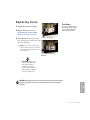
Replacing Fuses
Fuse Blocks
To locate the appropriate fuse
and replacement part number,
refer to the wiring diagrams
that came with your dryer.
1 Unplug the main power supply.
2 Remove the dryer’s cover. See
Troubleshooting section entitled,
Removing the cover on the dryer.
3 Check the fuse. If necessary, pull the
Fuses - in service
fuse out and replace it with a fuse of the
same type and rating.
✐
NOTE: Fuses have low resistance, if a
fuse has infinity resistance it is blown.
Fuses must be replaced with a fuse of
the same rating.
Fuse blocks open for
service.
IMPORTANT: Always refer
to the wiring diagrams that
came with your dryer to
locate specific electrical
components. Illustrations in
the User Guide are intended
to be representative only.
Tr o u b l e s h o o t i n g l 6 - 9
6
Troubleshooting
CAUTION: Always disconnect and lock out the main power sources before making
electrical connections. Electrical connections should be made only by qualified
personnel.
Check/Replace Heater Solid State
Relays
1 Disconnect and lockout the main power supply.
IMPORTANT: Always refer
to the wiring diagrams that
came with your dryer to
locate specific electrical
components. Illustrations in
the User Guide are intended
to be representative only.
2 Remove the cover on the dryer. See Troubleshooting section entitled,
Removing the cover on the dryer.
3 Locate the solid state relay. Refer to the wiring diagrams that came with your
dryer.
4 Check resistance using an ohmmeter. To check with ohm meter, measure
CAUTION: Always
disconnect and lock out
the main power sources
before making electrical
connections. Electrical
connections should be
made only by qualified
personnel.
the resistance across the terminals.
5 Replace the solid state relay, if necessary. If ohms equal zero replace the solid
state relay.
Solid state relay
If ohms equal zero replace the relay.
6 - 1 0 l Tr o u b l e s h o o t i n g
Checking the Heater
1 Unplug the main power supply.
2 Remove the cover on the dryer. See Troubleshooting section entitled,
IMPORTANT: Always refer
to the wiring diagrams
that came with your dryer
to locate specific electrical components.
Illustrations in the User
Guide are intended to be
representative only.
Removing the cover on the dryer.
3 Locate the solid state relay. Refer to the wiring diagrams that came with your
dryer.
120 volt dryer
Heater
Resistance
1 kW*
5-7Ω
2 kW*
10 - 15 Ω
*Models SL2.5, 5 and 15
*Models SL25 and 50
220 volt dryer
Heater
Resistance
1 kW
10 - 15 Ω
2 kW
20 - 25 Ω
*Models SL2.5, 5 and 15
*Models SL25 and 50
5
Tr o u b l e s h o o t i n g l 6 - 1 1
6
4
CAUTION: Always
disconnect and lock out
the main power sources
To check with ohm meter, measure the resistance across the heater. See the
before making electrical
chart above to determine if the resistance you measured falls within the accept- connections. Electrical
able specified range for your dryer.
connections should be
made only by qualified
Replace the sensor, if necessary.
personnel.
Troubleshooting
This photo represents an acceptable resistance rating on a 120 volt
dryer with a 2 kW heater.
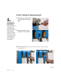
Replacing the Heater Assembly
1 Disconnect and lockout the main power. If you have mounted a loader or vacCAUTION: Always disconnect
and lock out the main power
sources before making electrical connections. Electrical connections should be made only
by qualified personnel.
uum receiver on the hopper, disconnect the material inlet hose at the source.
2 Disconnect the compressed air supplied to the dryer.
3 Remove the dryer’s plastic cover. Remove two screws securing the cover in
place. IMPORTANT! Be sure to support the cover so that you do not strain
the wiring on the back of the control.
4 Unscrew (counter-clockwise) the
ring on base of the pressure regulator until the ring comes off. It may
be necessary to use channel locks to
carefully remove the ring.
5 Disconnect hoses from the pressure switch. Note their location and then disIMPORTANT: Always refer
to the wiring diagrams that
came with your dryer to
locate specific electrical
components. Illustrations
and photographs in the
User Guide are intended to
be representative only.
connect the hose coming from the heater outlet from the low pressure side of
the switch and the hose coming from the heater inlet from the high pressure
side of the switch. The switch is marked with an “H” for high and an “L” for
Low. It will be important to remember these connections for reassembly.
6 Unwire the heater. Note their locations then remove the wires that are connected to the heater. Refer to the wiring diagrams supplied with your unit.
7 Loosen the clamp the connects the supply hose to the casting.
(continued)
6 - 1 2 l Tr o u b l e s h o o t i n g
Replacing the Heater Assembly
(continued)
8 Remove the heater assembly. Hold the regulator in
place and unthread the heater in a counter-clockwise
direction.
9 Reverse the procedure to reassemble.
10 Check the resistance on the heater before
supplying power to the unit. See Troubleshooting
section entitled, Checking the heater.
CAUTION: Always disconnect and lock out the main power sources
before making electrical connections. Electrical connections should be
made only by qualified personnel.
6
Troubleshooting
Tr o u b l e s h o o t i n g l 6 - 1 3
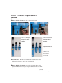
Replacing the Airflow Differential
Pressure Switch
CAUTION: Always disconnect
and lock out the main power
sources before making electrical connections. Electrical connections should be made only
by qualified personnel.
1 Disconnect and lockout the main power. If you have mounted a loader or vacuum receiver on the hopper, disconnect the material inlet hose at the source.
2 Disconnect the compressed air supplied to the dryer.
3 Remove the dryer’s plastic cover. Remove two screws securing the cover in
place. IMPORTANT! Be sure to support the cover so that you do not strain
the wiring on the back of the control.
4 Note their locations, then remove
the two spade terminals/wires connected to the pressure switch. Refer
to the wiring diagrams supplied with
your unit. It will be important to
remember these connections for
reassembly.
IMPORTANT: Always refer
to the wiring diagrams that
came with your dryer to
locate specific electrical
components. Illustrations
and photographs in the
User Guide are intended to
be representative only.
5 Note their locations then disconnect
hoses from the pressure switch.
Disconnect the hose coming from the
heater outlet from the low pressure side of
the switch and the hose coming from the
heater inlet from the high pressure side of
the switch. The switch is marked with an
“H” for high and an “L” for Low. It will
be important to remember these connections for reassembly.
6 Remove the mounting hardware securing the pressure switch to the
casting.
6 - 1 4 l Tr o u b l e s h o o t i n g
(continued)
Replacing the Airflow Differential
P r e s s u r e S w i t c h (continued)
8
Connect the hose coming from the heater outlet to the low pressure side
of the switch and the hose coming from the heater inlet to the high
pressure side of the switch.
9
Connect the two wires to their original location on the pressure switch.
10
Test the system. Make sure that the new air flow differential switch is
detecting the pressure drop between the heater inlet and outlet.
11
Reinstall the cover on the closure.
IMPORTANT: Always
refer to the wiring diagrams that came with
your dryer before making electrical connections.
CAUTION: Always disconnect and lock out the main power sources
before making electrical connections. Electrical connections should be
made only by qualified personnel.
6
Troubleshooting
Tr o u b l e s h o o t i n g l 6 - 1 5
6 - 1 6 l Tr o u b l e s h o o t i n g
We ’ r e H e r e t o H e l p
Conair has made the largest investment in customer support in the plastics industry. Our service
experts are available to help with any problem you might have installing and operating your equipment. Your Conair sales representative also can help analyze the nature of your problem, assuring
that it did not result from misapplication or improper use.
How to Contact Customer Service
To contact Customer Service personnel, call:
✐
Additional manuals and
prints for your Conair
equipment may be
ordered through the
Customer Service or
Parts Department for a
nominal fee. Most manuals can be downloaded
free of charge from the
product section of the
Conair website.
www.conairgroup.com
NOTE: Normal operating hours are 8:00 am - 5:00 pm. After hours emergency
service is available at the same phone number.
From outside the United States, call: 814-437-6861
You can commission Conair service personnel to provide on-site service by contacting the
Customer Service Department. Standard rates include an on-site hourly rate, with a one-day
minimum plus expenses.
B e f o r e Yo u C a l l . . .
If you do have a problem, please complete the following checklist before
calling Conair:
❒ Make sure you have all model, control type from the serial tag, and parts list numbers for your
particular equipment. Service personnel will need this information to assist you.
❒ Make sure power is supplied to the equipment.
❒ Make sure that all connectors and wires within and between control systems and related components have been installed correctly.
❒ Check the troubleshooting guide of this manual for a solution.
❒ Thoroughly examine the instruction manual(s) for associated equipment, especially controls. Each
manual may have its own troubleshooting guide to help you.
❒ Check that the equipment has been operated as described in this manual.
❒ Check accompanying schematic drawings for information on special considerations.
Appendix l A-1
Equipment Guarantee
Conair guarantees the machinery and equipment on this order, for a period as
defined in the quotation from date of shipment, against defects in material and
workmanship under the normal use and service for which it was recommended
(except for parts that are typically replaced after normal usage, such as filters,
liner plates, etc.). Conair’s guarantee is limited to replacing, at our option, the part
or parts determined by us to be defective after examination. The customer assumes
the cost of transportation of the part or parts to and from the factory.
Pe r f o r m a n c e Wa r r a n t y
Conair warrants that this equipment will perform at or above the ratings stated in
specific quotations covering the equipment or as detailed in engineering specifications, provided the equipment is applied, installed, operated and maintained in the
recommended manner as outlined in our quotation or specifications.
Should performance not meet warranted levels, Conair at its discretion will
exercise one of the following options:
• Inspect the equipment and perform alterations or adjustments to satisfy
performance claims. (Charges for such inspections and corrections will be
waived unless failure to meet warranty is due to misapplication, improper
installation, poor maintenance practices or improper operation.)
• Replace the original equipment with other Conair equipment that will meet
original performance claims at no extra cost to the customer.
• Refund the invoiced cost to the customer. Credit is subject to prior notice by the
customer at which time a Return Goods Authorization Number (RGA) will be
issued by Conair’s Service Department. Returned equipment must be well crated
and in proper operating condition, including all parts. Returns must be prepaid.
Purchaser must notify Conair in writing of any claim and provide a customer receipt
and other evidence that a claim is being made.
Wa r r a n t y L i m i t a t i o n s
Except for the Equipment Guarantee and Performance Warranty stated
above, Conair disclaims all other warranties with respect to the equipment,
express or implied, arising by operation of law, course of dealing, usage of
trade or otherwise, including but not limited to the implied warranties of
merchantability and fitness for a particular purpose.
A-2 l Appendix
Determining Airflow in the
SlimLine Dryer
Optimizing your compressed air consumption is critical to energy savings.
There are two main ways to determine your compressed air usage:
1.
Relate the heater inlet pressure to the airflow. (accuracy is limited)
2.
Calculate the airflow by using specific heat and the differential temperature of the air through the heater.
Relating the Heater Inlet Pressure
to the Air Flow
Determining your compressed air usage by this method is limiting because the
CFM readings are based on an empty hopper. When material is present in the
hopper the airflow drops below the charts specified pressure due to the additional
airflow restriction caused by the material. This measurement does provide a useful estimate, but is not precise because all material does not produce the same air
flow restriction.
SlimLine
Model
Pressure
Applied
(PSI)
SL2.5
and
SL5
2
3
4
5
6
7
2
3
4
5
6
7
2
3
4
5
6
7
SL15
To use the relationship between the heater inlet pressure and air flow to determine your compressed air usage:
1 Read the inlet pressure on the pressure gauge of the SlimLine dryer.
There are marks indicating the regulated pressure in PSI on the regulator.
The green range is 2-7 psi {0.14 - 0.48 bar}
2 Use the chart on the right to relate your reading to the airflow listed in
SL25
and
SL50
Measured
Flow
SCFM
2.0
2.9
3.7
4.5
5.0
5.3
6.17
7.42
8.5
9.0
9.5
10
16
18
21
23
26
27
the chart.
(continued)
Appendix l B-1
Calculating the Airflow through the
Hopper to Specify the Mass of Air
The most accurate way calculate your airflow is to determine how much the temperature is increased by the actual heat input.
To specify the mass or air use the following equation:
Q = M * C * (Tout - Tin) where Q is the heat input, M is the mass of the air, C is
the specific heat or air and Tin, Tout are the temperature in and out of the heater
respectively.
Then rearranging and adding units:
1 SCFM = (% on * Kw * 3413)/(0.075 * 60 * 0.24 * (Tout -Tin) )/100
2 SCFM = (% on * 31.08/Tout - Tin) for the SL 2.5/5/15
✐
3 SCFM = (%on * 62.16)/(Tout -Tin) for the SL25/50
NOTE:
The percent (%) on number can be read from the first menu displayed on the controller, by pressing the green return button one (1) time. This number should only be
read after the unit has had time to stabilize at the setpoint temperature.
Tout (temperature out)- the setpoint temperature (°F)
Tin (temperature in) - The compressed air supply temperature to the dryer (usually
close to the ambient temperature) (°F)
SCFM - Air flow in cubic feet per minute of air at standard density (0.075 lb/ft^3).
B-2 l Appendix
RT D r e s i s t a n c e c h a r t
You can use the following chart to determine if you need to replace your RTD.
Appendix l C-1
Compressed Air Membrane Option
This option is necessary when the compressed air supplied does not meet the
40º F {4º C} dewpoint. The membrane serves as a refrigerant air conditioner and
reduces the dewpoint to the 40º F {4º C} dewpoint specification. The included
filters aid in cleaning the compressed air.
Replacement filters are
available from Conair.
Contact Conair Parts
1 800 458 1960
From outside of the United
States, call:
814 437 6861
The membrane is specifically designed to remove water vapor. Dryer performance and life will be reduced if liquid water or liquid compressor oil enters the
dryer. Filter(s) must be installed in front of the dryer to remove both liquid water
and oil aerosols if present in your plant's compressed air system.
Preparing to Install the Membrane
CAUTION: Air under high
pressure
1 The membrane assembly can be used with oil lubricated, water lubricated or non-lubricated compressors.
2 Always install a drainable drip leg prior to the inlet filtration to the
This equipment uses compressed air delivered at
rates up to 150 PSI
{10.3 bar} to dry plastic
materials.
To prevent possible injury,
wear eye protection when
operating this equipment.
Always disconnect the compressed air supply before
performing maintenance or
troubleshooting.
membrane assembly. This helps prevent the accumulation of water at low
points that could overwhelm the water handling capability of the filter.
3 Before installing the membrane assembly verify that:
a. The maximum pressure that could be encountered is less than the dryer
150 psi {10.3 bar} and filter rated pressure.
b. The compressed air supply temperature and ambient temperature at the
membrane assembly will not exceed 150º F {66º C}.
c. The dryer sweep air (located at the bottom of the longest membrane container) will not be obstructed.
d. The line sizes are adequate for the air flow and allowable pressure drop
(Adequate size would be the same size as dryer or larger.)
(continued)
D-1 l Appendix
Preparing to Install the Membrane
(continued)
4 The membrane option and any related prefiltration equipment is
designed to be mounted in a vertical position. In most cases, we do not recommend supporting the module with the process piping. We recommend piping supports be located on either side of, directly in front of, or behind the
dryer and filters. Support brackets are supplied with the membrane assembly
to simplify your installation.
✐
NOTE: It is important for maximum membrane life, that the appropriate filtration system be used with the membrane and the dryer. Proper prefiltration will ensure the effective removal of particulates, water, compressor
lubricant oil, and other types of contaminants. This is best accomplished by
the use of the integrated pre-filtration. Damage to the membrane and/or
the dryer or dew point degradation may result if the prefiltration is
removed or relocated at a distance away from the installation.
U s i n g t h e Wa l l M o u n t B r a c k e t s t o
Mount the Membrane Assembly
The membrane assembly is supplied with wall mounting brackets. If you choose
to use the supplied mounting brackets:
1 Mount bracket to filter head. Remove four (4) screws holding
black plastic top cap to filterhead. Then, place bracket on filter
head over plastic cap. Install screw supplied with bracket.
CAUTION: You are responsible for the structural integrity of this installation.
Appendix l D-2
Mounting the Differential Pressure
Gauge to the Filterhead
( i f n o t fa c t o r y i n s t a l l e d )
1 Make certain o-rings are in place on the bottom of the gauge body.
2 Connect the low pressure transmission bolt (bolt next to the red band on
gauge) to the gauge port at the filter outlet (downstream side of the filter).
3 Connect the high pressure transmission bolt (bolt next to green band on
gauge) to the gauge port at the filter inlet (upstream side of filter).
4 Use a flathead screwdriver to tighten/loosen bolts. The tip width of the
screwdriver should be a least 3/8 inch {9.5 mm}. Torque bolts to 25
+/- 5 inch oz. Do not overtighten.
CAUTION: Air under high
pressure
Installing the compressed air
piping for membrane assembly
installation
1 Before installing, blow out pipe line to remove scale and other foreign
matter.
This equipment uses compressed air delivered at
rates up to 150 PSI to dry
plastic materials.
To prevent possible injury,
wear eye protection when
operating this equipment.
Always disconnect the compressed air supply before
performing maintenance or
troubleshooting.
2 Mount so that inlet and outlet connections are horizontal (filter bowl
vertical) to ensure proper liquid
drainage.
IMPORTANT: You should not use threaded
sealant tape on the compressed air connections. Use of these items can contami-
Filter bowls
nate your compressed air circuit. A quick
disconnect fitting may be used to facilitate
easy air line connection and removal for
the main supply line, but the fitting should
not be the type that restricts air flow.
D-3 l Appendix
(continued)
Installing the compressed air
piping for membrane assembly
i n s t a l l a t i o n (continued)
Airflow direction
4 Install so that the air flow direction is in the direction of
arrows on the filterhead.
NOTE: Make certain flow direction through filters is correct
(observe pin hole used for aligning top caps). When hole is on
side closest to you, inlet is to left.
Isolation
valve installation
recommended
(not included)
5 For ease of service, Conair recommends that an isolation valve (not included) is installed on the compressed
air line leading to the membrane assembly.
Membrane Installation
1 A typical membrane assembly installation is shown below.
CAUTION: Always wear protective eyewear when working with compressed air.
Appendix l D-4
Membrane Installation
(continued)
WARNING: Disconnect power and compressed air before servicing.
Always disconnect and lock out power and compressed air supplies to this equipment
before performing maintenance or repair. Failure to do so could result in personal injury
caused by the unexpected energizing of this equipment.
2 Prior to installing the membrane, slowly open the compressed airline
shut off valve and relieve any accumulated pressure. Allow any accumulated water, oil, or particulates to blow out. Use extreme caution to prevent
accidents and injuries during this operation.
3 Disconnect and isolate the compressed air supply leading to the area
where you will be installing the membrane. If you are installing the
membrane onto an existing dryer installation make sure that you disconnect and lock out the main power supplied to the dryer.
CAUTION: Air under high
pressure
Isolating the
compressed
air source.
This equipment uses compressed air delivered at
rates up to 150 PSI to dry
plastic materials.
To prevent possible injury,
wear eye protection when
operating this equipment.
Always disconnect the compressed air supply before
performing maintenance or
troubleshooting.
D-5 l Appendix
4 Connect the compressed air supply
Isolation/Shut-off
to the filter. The coalescing filter
valve
should be as close to the dryer as practical to prevent cooling of the air and
condensation of water and oil between
the coalescing filter and the dryer. An
isolation/shut-off valve (ball or gate
valve) the same size as the supply line
should be installed before the filter and
dryer so that the dryer and application Connecting the compressed air
can be isolated.
supply.
(continued)
Membrane Installation
(continued)
5 Connect the compressed air supply
(dry air outlet) to the SlimLine.
Connecting the
compressed air supply
from the filter to the
dryer.
6 The automatic filter drains may discharge oil and water. Route the filter
drain line to a suitable location in
compliance with local regulations.
Filter drains
Appendix l D-6
Start-up and Operation
1 Slowly open up the upstream isolation valve compressed air supply to the
CAUTION: Air under high
pressure
dryer/membrane unit. Maximum pressurization rate of 15 psi/sec. Check for
any possible leaks. Listen, and feel for leaks, you can use a bubble soap solution to help locate possible leaks. IMPORTANT: Do not operate filter at pressures in
This equipment uses compressed air delivered at
rates up to 150 PSI {10.3
bar} to dry plastic materials.
excess of the maximum working pressure of 150 psi.
To prevent possible injury,
wear eye protection when
operating this equipment.
Always disconnect the compressed air supply before
performing maintenance or
troubleshooting.
✐
NOTE: Prefilters: The automatic drain may leak air until the pressure builds up to
about 10 psi {0.69 bar} and will then seal except when discharging accumulated
water and oil.
2 The filter differential pressure indicator(s) and drain(s) should be
inspected on a regular schedule, preferably as least weekly. If the filter
differential pressure indicator enters the red area on either the prefilter or coalescing filter, both of the filter element(s) must be changed. It is recommended
that replacement filter elements be kept on hand as spares for fast changeouts to eliminate down time.
Red area
indicates filter
needs to be
changed.
Smaller-sized membrane assemblies come
equipped with the filter differential pressure
indicator shown above. The red area on the
prefilter indicates that both filter elements
should be changed.
✐
✐
Larger-sized membrane assemblies come
equipped with the filter differential pressure indicator shown above. If either the
prefilter or the coalescing filter enter the
red area both filter elements should be
changed.
NOTE: If filter life remains less than six months with a prefilter installed, compressor maintenance
or excessive line corrosion and/or contamination is indicated.
NOTE: If any decrease is observed in the drain rate, the filter should be depressurized and the bowl
removed. If the liquid level in the bowl is above the automatic drain float, the automatic drain is not operating correctly and should be replaced.
(continued)
D-7 l Appendix
Start-up and Operation
(continued)
3 Filter element(s) should be replaced on a regular schedule (preferably
every six months). See Appendix D section entitled, Filter Element
Replacement.
4 To shutdown the membrane assembly turn off the air supply and allow
the pressure to decrease to atmospheric. Maximum de-pressurization of 15
psi/sec.
IMPORTANT: Do not operate filter at pressures in excess of the maximum working
pressure of 150 psi.
✐
NOTE: Maximum operating temperature of the membrane assembly is
150º F {38º C}.
M a i n t e n a n c e a n d Tr o u b l e s h o o t i n g
WARNING: Disconnect power and compressed air before servicing.
Always disconnect and lock out power and compressed air supplies to this
equipment before performing maintenance or repair. Failure to do so could
result in personal injury caused by the unexpected energizing of this equipment.
The only routine maintenance required is replacement of the filter element(s)
every six months and rebuilding or replacing the drain mechanism annually.
The are no repairable components within the membrane. The membrane must
be replaced if damaged or oil soaked.
To ensure performance of the membrane and to obtain maximum compressor
life, all compressor maintenance schedules recommended by the compressor
manufacturer should be followed.
Appendix l D-8
M a i n t e n a n c e / Tr o u b l e s h o o t i n g
Checkpoints
Check flow, pressure, and temperature to make certain filter is being operated
within design conditions.
• High dewpoint - Before attempting to troubleshoot the membrane verify that the dry air flow rate is at or below the design level of the membrane
assembly (150 psi {10.3 bar}). High air flow will result in high dew points.
The most likely cause of the high dew point is low air supply pressure, due to either low pressure to the filters or high pressure drop across
the filters. The latter will be indicated by the filter differential pressure
indicator.
Another possible cause of high dew point is failure of the automatic drains.
Manually open the drain.
✐
NOTE: Pressure drop should never exceed 50 psi {3.4 bar}.
• Check pressure drop across the filter
Pressure differential in excess of 6 psi {0.41 bar} or pressure indicator in red area means that the filter sleeve or element should
be replaced.
• Check for sudden reduction in pressure drop.
This might indicate: A possible leak across element o-ring seal or a leak
through the element due to physical damage.
• Check to see that filter is installed level to ensure proper drainage.
• Check that manual drains are drained periodically or that automatic drains are functioning.
• On models with liquid level sight glass check that liquid level is
below top of sight glass.
D-9 l Appendix
Filter Elements
If the filter differential pressure indicator shows red, filter elements must be
changed. Continuing to operate for an extended period after the filter differential
pressure indicator(s) have changed completely to red could result in low air pressure, high dew points, and eventually in failure of the filter element leading to
contamination and damage of the dryer.
If filter element life remains less than six months with a prefilter installed, compressor maintenance or excessive line corrosion or contamination is indicated.
When to Replace a Filter Element
✐
a. Initial (dry) pressure drop: 1 psi {0.07 bar} to 2 psi {0.14 bar}.
b. Operating pressure drop: As filter becomes liquid loaded (wetted), pressure
drop will increase to 2 to 6 psi {0.14 bar to 0.41 bar}. Further pressure drop
occurs as element loads with solid particles.
NOTE: Pressure drop
may temporarily increase
when flow is resumed
after flow stoppage.
Pressure drop should
return to normal within
one hour.
Filter Element Replacement
This filter is a pressure containing device. Depressurize before servicing isolate
and completely depressurize filter before proceeding.
WARNING: Disconnect power and compressed air before servicing.
Always disconnect and lock out power and compressed air supplies to this
equipment before performing maintenance or repair. Failure to do so could result
in personal injury caused by the unexpected energizing of this equipment.
(continued)
Appendix l D-10
Filter Element Replacement
1 Isolate filter close inlet and outlet
WARNING:
Disconnect power
and compressed air
before servicing.
Always disconnect and
lock out power and
compressed air supplies to this equipment
before performing
maintenance or repair.
Failure to do so could
result in personal injury
caused by the unexpected energizing of
this equipment.
valves if installed or shutoff air
supply.
2 Depressurize filter by slowly
opening drain valve manually.
3 Remove the bowl. Push the bowl up, turn bowl 1/8 turn to your left, and pull
bowl straight down.
(continued)
D-11 l Appendix
Filter Element Replacement
(continued)
4 Remove the filter elements. Pull off old element and discard.
This is an example
of a smaller-sized
membrane disassembled.
This is an example
of a large-sized
membrane disassembled.
Replacement filters are
available from Conair.
Contact Conair Parts
1 800 458 1960
From outside of
United States, call:
814 437 6861
5 Clean filter bowl. The filter bowl and automatic drain should be washed
with warm soapy water to remove any accumulated oil.
6 Replace the filter element. Make certain the o-ring inside the top of the
replacement filter element is in place and push the filter element onto the filterhead.
(continued)
Appendix l D-12
Filter Element Replacement
(continued)
7 After making certain that o-ring inside top of bowl and the wave spring
are in place, reassemble bowl to head.
✐
✐
✐
NOTE: Do not handle elements by outside foam cover. Handle by bottom
end cap only.
NOTE: Make certain o-ring is generously lubricated.
NOTE: Wave spring ends should be pointed down to prevent wave spring
from interfering with reassembly.
Automatic Draining Mechanism
✐
✐
NOTE: Collected liquids must be removed to ensure proper
operation.
NOTE: Depressurize slowly, to avoid filter element damage.
1 Membrane assemblies are equipped with automatic drains. Liquids will
✒Tip: Manually drain
internal auto drains daily
to verify drain function.
✒Tip: It is recommended
that drain mechanism be
replaced annually.
D-13 l Appendix
automatically discharge when a sufficient accumulation occurs. These
drains may be manually drained by turning to your right (clockwise) to open
and to your left (counterclockwise) to close.
IMPORTANT: If a high water level is observed in a filter liquid level indicator,
the automatic drain is not functioning correctly. The dryer should be shut
down and the drain mechanism should be repaired or replaced before proceeding. Extended operation with malfunctioning automatic drain(s) could
result in liquid water and oil entering the dryer, resulting in elevated dew
points and damage to the membrane assembly and/or dryer.
Drain Provisions
The bottom of internal automatic drains are provided with 1/8 inch (inside
threads) for connection of a drain line if desired.
Discharge is at system pressure; anchor drain line
Appendix l D-14